Table of Contents
Advertisement
Quick Links
Document-No.
Issue
Dated
Postal address
Phone
Fax
eMail
Internet
Copyright
Technical modifications
E461605
02
15.02.2012
Christ-Elektronik GmbH
Alpenstraße 34
DE-87700 Memmingen
+49 (0)8331 8371 – 0
+49 (0)8331 8371 – 99
info@christ-elektronik.de
http://www.christ-elektronik.de
It is forbidden to reproduce or process (using electronic systems), copy or distribute any
part of this document. Translation into another language requires written authorisation.
This document is for the personal use of the owner of the device or Christ-Elektronik
GmbH personnel only.
Christ-Elektronik GmbH reserves the right to modify the designations, specifications and
technical data without prior notice.
Instruction manual
Wattmeter
CPM138-AC
Advertisement
Table of Contents

Subscribe to Our Youtube Channel
Related Manuals for Christ Elektronik CPM138-AC


Summary of Contents for Christ Elektronik CPM138-AC
- Page 1 Instruction manual Wattmeter CPM138-AC Document-No. E461605 Issue Dated 15.02.2012 Postal address Christ-Elektronik GmbH Alpenstraße 34 DE-87700 Memmingen Phone +49 (0)8331 8371 – 0 +49 (0)8331 8371 – 99 eMail info@christ-elektronik.de Internet http://www.christ-elektronik.de Copyright It is forbidden to reproduce or process (using electronic systems), copy or distribute any part of this document.
-
Page 2: Table Of Contents
Table of contents Seite 1 Description ..................................2 1.1 General Description ..............................2 1.2 Safety instructions ..............................2 1.3 Repairs ..................................2 2 Operation ..................................3 2.1 Installation instructions ............................. 3 2.2 Inbetriebnahme ................................3 2.3 Controls ..................................3 2.4 Modes of operation ..............................4 2.5 Operating Philosophy .............................. -
Page 3: Description
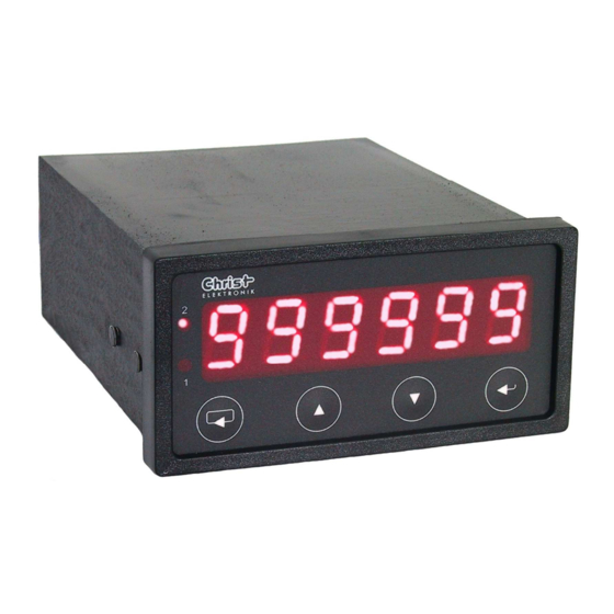
1 Description 1.1 General Description The measuring instrument CPM138-AC allows universal measurements of electrical parameters. Its six- digit display is freely scalable. There is also an optional standard-signal output (voltage 0...10 V, current 0(4)...20 mA) for the measurement values. The measurement values can also be used to control two re- lay switches using pre-defined thresholds. -
Page 4: Operation
2 Operation 2.1 Installation instructions Place the measuring instrument into the designated cut-out (according to DIN 43 700, dimensions: 92mm x 45mm) on the front of your device frame. Please use the enclosed fastening parts to attach the instrument. Tighten the fastening bolts alternately until the instrument is securely fastened. When plac- ing this instrument, consider any radiant heat of neighbouring devices, and also take into account the permissible ambient temperature. -
Page 5: Modes Of Operation
2.4 Modes of operation Setting the mode of operation (E_Mod) will select which measurement parameter is to be displayed permanently. Depending on the settings, the measured values will either be displayed with 0 to 4 posi- tions after the decimal point or, automatically, with 6 digits (automatic display range selection). Only the "minus"... -
Page 6: Operating Philosophy
2.5 Operating Philosophy This instrument can be controlled using the push buttons on the front panel, or the optional interface. Manual control is done via a menu interface, which is divided into a Display and a Setup Menu. For easier differentiation, the decimal point (the point in the right 7-segment digit for integer values) is flashing in the display menu. -
Page 7: Editing Of Parameters
2.5.3 Editing of Parameters When editing parameters, the current value is displayed with the highest resolution possible. The least- significant position (digit) is flashing and can be increased or decreased by 1 using the buttons while the validity of the settings range is continuously verified. The next position, and its leading sign if applicable, can be selected by pressing the button Changes are confirmed and stored in the EEPROM with the button , or cancelled by pressing the but-... -
Page 8: Deleting The Stored Min And Max Values
E_tM (List) tM=0.5 Measurement rate 0.5 s tM=1.0 Measurement rate 1.0 s E_CodE (Value) Code assignment (default 0831.) E_SiM (Value) Simulation value for ConSt mode E_ConF (List) nonE No interface A-oUt Analogue output ... -
Page 9: Tara Value
2.9 Tara value The display menu item d_tArA allows polling the current tare value (scale offset/correction). The stored tare value can be deleted (cleared) by pressing the buttons (RESET) simultaneously. As a confir- mation, CLEAr is displayed for a short time. The current tare value can either be changed via the setup menu (E_tArA), or set to the currently dis- (TARE) simultaneously. -
Page 10: Beschreibung Der Ausgänge
3 Beschreibung der Ausgänge 3.1 Threshold contacts (Relays) The relays are triggered depending on the currently measured values. The threshold values (switch thresholds), the hysteresis/alarm mode and the switching type (close or open relay) can be set for each of the two relays separately. -
Page 11: Serial Interface
Only the minus sign gets transferred as a leading sign. The CPM 138 can be operated completely via the interface using the commands described below ("command mode"). With the Blockmode Command „L1“ the CPM138-AC send the measurment data in the following for- mat: Datastring: Voltage[V];Current[A];Activepower[W];Apparentpower[VA];Reactivepower[var];Powerfactor;... -
Page 12: Interface Commands
3.3.2 Interface commands A transfer control mechanism in the form of an XON/XOFF protocol is necessary for bidirectional oper- ation of the interface because the computer needs to know whether the most recently transferred com- mand has already been interpreted and executed. If not, a command could be overwritten. The ASCII character 13 (CR) is used to mark the end of a command sequence in both directions. - Page 13 Table 5 All interface commands in alphbetical order: Setup Polling Command Command Min. Max. Preset Value Explanation Corresponds Command Command Type Description Parameter Parameter to Menu Item Value Value or Buttons Minimum Minimum value d_Lo AA-Norm Analogue output type A_SiG 0: 0 …...
- Page 14 Energy_S Apparentenergy Energy_Q Reactiveenergy Time Time Resolut. 0...4 decimals after E_rES the point (fixed) 5: automatic display range selection...
-
Page 15: Error Handling
4 Error handling Error messages can be acknowledged by pressing the buttons (RESET) simultaneously. Errors are displayed for approximately 10 seconds without prioritisation. If an error message does not get acknowledged, all further messages are lost. Error messages are not stored when the device is switched off. -
Page 16: Technical Specifications
5 Technical specifications Display: Six-digit, 7-segment display, 13 mm red LEDs; display range: –99999 to 999999 digits Decimal point: Menu-based choice between 0 and 4 positions after the decimal point, and automatic display range selection Threshold contact display: 2 red LEDs, 3 mm Controls: 4 foil push buttons Measurement principle:... - Page 17 Threshold contacts: Two electrically isolated relay contacts (change-over contacts), max. load: 250 V , 8 A, switching delay depending on measurement rate. Switch mode can be selected from min/max contact or alarm. Threshold value, hysteresis and switching logic can be set freely; in case of broken sensors or short circuits, both relays are open (basic state) Analogue output: Electrically isolated;...
Need help?
Do you have a question about the CPM138-AC and is the answer not in the manual?
Questions and answers