
Related Manuals for Pentair BERKELEY 4BSD


Summary of Contents for Pentair BERKELEY 4BSD
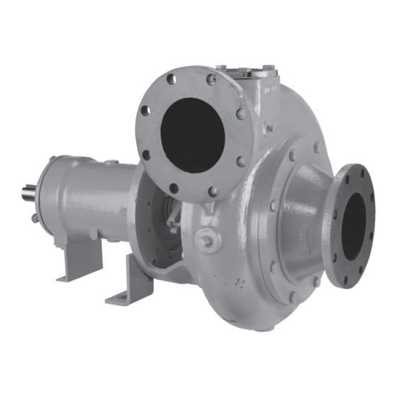
- Page 1 OWNER’S MANUAL End-Suction Solids-Handling Pumps 4BSD, 5BSD, 6BSD, and 8BSD 6192 0310 293 WRIGHT STREET, DELAVAN, WI 53115 WWW.BERkELEyPumPS.COm PH: 888-782-7483 BE888 (02/28/14) © 2014 Pentair Ltd. All Rights Reserved.
-
Page 2: Loss Or Damage In Transit
LOSS OR DAMAGE IN TRANSIT Immediately upon receipt, a complete inspection and freight carrier. Berkeley will assist the customer in receiving accounting against the packing list should be made of all fair compensation, but assumes no responsibility to mediate major components, and accompanying boxes or pallets. such claims. -
Page 3: Table Of Contents
TABLE OF CONTENTS LOSS OR DAMAGE IN TRANSIT ....................2 PUMP/MOTOR IDENTIFICATION ....................2 WARRANTY ...........................4 PRESTART-UP AND START-UP CHECKLIST ................5 SAFETY INSTRUCTIONS ......................6 INTRODUCTION ..........................6 INSTALLATION ..........................7 OPERATION ..........................8 TROUBLESHOOTING .........................10 PREVENTIVE MAINTENANCE ....................12 CORRECTIVE MAINTENANCE ....................13 WEAR RINGS ..........................15 COUPLING REMOVAL AND INSTALLATION ................16 MECHANICAL SEALS ........................16 TECHNICAL DATA ........................17 Congratulations! You are the new owner of the finest... -
Page 4: Warranty
Limited Warranty BERKELEY warrants to the original consumer purchaser (“Purchaser” or “You”) of the products listed below, that they will be free from defects in material and workmanship for the Warranty Period shown below. Product Warranty Period Water Systems: whichever occurs first: Water Systems Products —... -
Page 5: Prestart-Up And Start-Up Checklist
PUMP/MOTOR PRESTART-UP AND START-UP CHECKLIST Contractor ________________________________________ Pump Serial Number ________________________________ Project Name ______________________________________ Pump Model Number ________________________________ Date of Shipment ___________________________________ Motor Serial Number ________________________________ Procedure Yes No N/A Comments 1. Shipment Was there any damage in transit? List) _________________________ Were all items received? (List) _________________________... -
Page 6: Safety Instructions
READ AND FOLLOW SAFETY Risk of crush injuries if pump is dropped. INSTRUCTIONS! The pump is heavy; use appropriate lifting gear if you must raise the pump. Take all normal precautions for This is the safety alert symbol. When you see this the weights involved (400 –... -
Page 7: Installation
Pump and driver should be located in an area that will discharge line and a closing valve in the suction line. The permit periodic inspection and maintenance. Head and check valve, between the pump and closing valve, protects access room should be provided and all units should be the pump from water hammer and prevents reverse rotation installed in a dry location with adequate drainage. -
Page 8: Operation
regulations concerning OSHA. instructions that may have been supplied with the pump. The final coupling alignment must be made after the piping V-Belt Drive has been connected. Realign as required. If sufficient A pump coupled to its driver by means of V-belts and adjustment is not achieved, piping may have to be sheaves may have been shipped separately from the drive disconnected to properly align the coupling. - Page 9 2. Close the discharge valve. 2. Close discharge valve. 3. Open the suction valve. Operating at Reduced Capacity 4. Start the priming system. Typical applications cover a wide range of flow rates, and 5. Run the priming system until a continuous stream a variable speed driver is often used to adjust the pump flows through the suction line, then close the vent capacity, which is taken into consideration by Berkeley when...
-
Page 10: Troubleshooting
TROUBLESHOOTING If you have followed the installation and start up procedures outlined in this manual, your pump should provide reliable service and long life. However, if operating problems occur, significant time and expense can be saved if you use the following checklist to eliminate the most common causes of those problems. - Page 11 TROUBLESHOOTING (continued) Symptom Probable Cause Corrective Actions Pump running at shut-off condition. Open discharge valve. Check for obstructions. Insufficient suction line submergence. Increase submergence. Air in liquid. Increase submergence to prevent vortexing. Impeller passages plugged. Clean impeller passages. Excessive lubricant. Drain lubricant as necessary.
-
Page 12: Preventive Maintenance
PREVENTIVE MAINTENANCE Proceed as follows during lubrication: NOTICE: Carefully read this section before attempting any Manufacturer Brand Name maintenance procedure. Refer to accessory equipment Atlantic Richfield ARCO M/P #2 manuals that may have been included. Chevron Dura-Lith To assure satisfactory operation of the pumps, routine inspection and periodic maintenance are required. -
Page 13: Corrective Maintenance
NOTICE: If the gap is not as specified, repeat this entire A. Prepare the pump for disassembly according to the following procedure: procedure until the proper clearance is achieved. Tighten the locknuts to insure that the jacksrews will remain 1. Lock out the power to the driver. in the proper position. - Page 14 H. Remove the thrust bearing deflector (A126). Burn hazard. Heated parts can cause I. Shaft Assembly: severe burns. Wear heat resistant gloves when handling T20 and T30 Frame Construction: heated parts. Remove the capscrews and jackscrews that secure K. Remove the lip seal (139A) from the thrust bearing the thrust bearing housing (139) to the frame (90).
-
Page 15: Wear Rings
After the parts have cooled, pack the radial bearing bearing deflector (B126) on the shaft (4). (163) and thrust bearing (168) half full of grease. B. Install the backhead (34) to the frame (90) and Refer to the bearing lubricating instruction in the secure with capscrews. -
Page 16: Coupling Removal And Installation
A. Remove any burrs or nicks on the sleeve (14) and apply Wear Ring Removal a light coat of liquid soap or liquid detergent. A. If the wear ring requires replacement, it can be removed NOTICE: Seal faces are lapped and polished to a mirror by heating it to 350 - 400 degrees F to break the finish. -
Page 17: Technical Data
TECHNICAL DATA Table 1: Pump Nominal Impeller Clearance Discharge Model Frame Nominal Size Number Size Impeller Clearance 4” 4BSD1 .010 - .020 4” 4BSD2 4” 4BSD3 .015 - .025 6” 6BSD3 4” 4BSD4 .010 - .020 4” 4BSD5 .008 - .015 5”... - Page 18 COUPLING GAP COUPLING GAP OFFSET LIMIT OFFSET LIMIT OFFSET ALIGNMENT OFFSET ALIGNMENT ANGULAR ANGULAR LIMIT = A – B LIMIT = A – B ANGULAR ALIGNMENT ANGULAR ALIGNMENT 5400M003 6151 0210 5400M001 6152 0210 Figure 2: Falk Coupling Alignment Figure 3: Woods Coupling Alignment TYPE E TYPE JES 5400M005...
- Page 19 140A A126 139A 168A B28L B126 B28R Hardware not indicated 6145 1010 NH Figure 5A: Assembly with Integral Fronthead (4BSD1, T20 Frame), product shown with volute oriented in T1 position Parts List – B85622 Item Description Part Number Item Description Part Number Impeller T4A1FG...
- Page 20 Only hardware shown 6145 1010 H Figure 5B: Assembly Hardware (4BSD1, T20 Frame) Parts List – B85622 Item Description Part Number Item Description Part Number Pipe Plug 20FM7D0002 0008 F Washers 11FM1N0009 0006 F Pipe Plug 20FM7A0006 0008 F Cap Screws 11FM7A0056 0001 F Pipe Plug 20FM7D0004 0008 F...
- Page 21 140A 139A B126 B126 168A B28L B28R Hardware not identified 6146 1010 NH Figure 6A: Assembly (4BSD2, T20 Frame, and 4BSD3, 6BSD3, T30 Frame), product shown with volute oriented in T1 position Parts List – B85626, B85632, B85633 Item Description B85626 B85632 B85633...
- Page 22 Only hardware shown 6146 1010 H Figure 6B: Assembly Hardware (4BSD2, T20 Frame, and 4BSD3, 6BSD3, T30 Frame) Parts List – B85626, B85632, B85633 Part Number Item Description B85626 B85632 B85633 Pipe Plug 20FM7D0004 0008 F 20FM7D0004 0006 F 20FM7D0004 0006 F Pipe Plug 20FM7D0002 0008 F 20FM7D0002 0008 F...
- Page 23 B126 A206 140A 139A A126 Hardware not indicated 6147 1010 NH Figure 7A: Assembly (4BSD4, T40 Frame), product shown with volute oriented in T1 position Parts List – B85649 Item Description Part Number Item Description Part Number Impeller T4D1AR Bearing Housing T40D139A 0220 F Shaft T40D4A 4180 F...
- Page 24 Only hardware shown 6147 1010 H Figure 7B: Assembly Hardware (4BSD4, T40 Frame) Parts List – B85649 Item Description Part Number Item Description Part Number Pipe Plug 20FM7D0004 0006 F Washers 11FM1N0011 0006 F Pipe Plug 20FM7A0002 0008 F Pipe Plug 20FM7D0001 0006 F HH Cover Capscrews 11FM7A0112 0001 F...
- Page 25 A206 B206 B126 A126 139A 6148 1010 NH Hardware not shown Figure 8A: T40 Assembly (4BSD5 and 5BSD6, T40 Frame), product shown with volute oriented in T1 position Parts List – B85650, B85651 Part Number Item Description B85650 B85651 Impeller T4E1E T5D1DC Shaft...
- Page 26 AN, AZ Only hardware shown 6148 1010 H Figure 8B: Assembly Hardware (4BSD5 and 5BSD6, T40 Frame) Parts List – B85650, B85651 Part Number Item Description B85650 B85651 Pipe Plug 20FM7D0004 0006 F 20FM7D0004 0008 F Pipe Plug 20FM7A0002 0008 F 20FM7A0002 0008 F HH Cover Capscrews 11FM7A0112 0001 F...
- Page 27 A206 B206 140A B126 139A A126 Hardware not identified 6149 1010 NH Figure 9A: Assembly (6BSD6 amd 8BSD6, T60 Frame), product shown with volute oriented in T1 position Parts List – B85652, B85653 Part Number Item Description B85652 B85653 Impeller T6E1BA T8F1N Shaft...
- Page 28 AF AY AN, AZ Only hardware shown 6149 1010 H Figure 9B: Assembly Hardware (6BSD6 amd 8BSD6, T60 Frame) Parts List – B85652, B85653 Part Number Item Description B85652 B85653 Pipe Plug 20FM7D0004 0008 F 20FM7D0004 0008 F Pipe Plug 20FM7A0003 0008 F 20FM7A0003 0008 F Pipe Plug...
- Page 29 3,4,5 Backhead (for reference) 6272 0910 Figure 10: DR1 – Dry Run Tank Assembly T20 FRAME T30 FRAME T60 FRAME Item Description Quantity Part Number Part Number Part Number Pipe Plug 20FM7A0006 0008 F 20FM7A0006 0008 F 20FM7A0006 0008 F Reservoir M14961 M14961...
- Page 30 MEASURE GAP CAPSCREW THRUST THRUST BEARING BEARING JACKSCREW LOCKNUT T20 AND T30 FRAME Scale IMPELLER CLEARANCE MEASURE GAP IMPELLER THRUST BEARING CAPSCREW IMPELLER CLEARANCE SHIM THRUST BEARING CLEARANCE SHIM O-Ring T60 FRAME TYPICAL VOLUTE IMPELLER ADJUSTMENT 6150 0210 5400M021 Figure 11: Impeller Adjustment...
Need help?
Do you have a question about the BERKELEY 4BSD and is the answer not in the manual?
Questions and answers