Table of Contents
Advertisement
Quick Links
Z-5R Relay Wiegand
www.ironlogic.me
Z-5R Relay Wiegand / Z-5R Relay Wiegand
Case Controllers
User Manual
1. OVERVIEW
Controllers Z-5R Relay Wiegand or Z-5R Relay Wiegand Case (modification with plastic case) are
used in Access Control Systems (ACS) as standalone controllers with output power relay that
operate external devices. As input devices a Dallas Touch Memory contactor (reader for DS1990A
keys), or a contactless proximity card reader emulating iButton (Dallas Touch Memory) or Wiegand
(26-42 bits) protocol can be connected.
The following equipment can be connected to a Z-5R Relay Wiegand controller:
- External proximity card reader, transmitting information via iButton protocol, or Dallas Touch
Memory contactor.
- Relay controlled lock;
- Lock release button (normally unlocked);
- External LED;
- External buzzer;
- Door sensor.
2. SPECIFICATIONS
- External reader connection protocol ..............iButton (Dallas Touch Memory), Wiegand (26-42 bits)
- Maximum number of keys.........................................................................................................1364
- DS1996L key support .................................................................................................................Yes
- Audiovisual indication..............................................................................................LED and buzzer
-External control for LED and buzzer ............................................................................................Yes
- Output for lock...........................................................................................................................relay
- Switching current (24В DC/120В АС), А..........................................................................................3
- Jumper for initial relay state selection.......................................................................................on/off
- Lock release duration timer................................................................0...220 s (factory default is 3
s)
- Power supply operating voltage, V............................................................................................8 - 18
- Maximum operating current....................................................................................................45 mA
- Case dimensions, mm ....................................................................................................65 x 65 x 20
- PCB dimensions, mm .....................................................................................................46 x 35 x 15
- Case material (for Z-5R Relay Wiegand Case)................................................................ABS plastic
A twisted pair cable (e.g. UTP CAT5) should be used to connect the reader or key probe to the
controller, to avoid interference. When connected via iButton (Dallas Touch Memory) protocol, one
wire of a twisted pair is used to connect GND terminals of the reader and the controller. Second wire
of this twisted pair is used for signal transmission, and connects the reader output with the D0
terminal on the controller (see Fig. 4 and 5).
The power to the reader can be delivered using a single wire. If unused wires remain in the cable,
connect them between GND terminals on the reader and the controller.
Page 1
Advertisement
Table of Contents

Related Manuals for Iron logic Z-5R Relay Wiegand


Summary of Contents for Iron logic Z-5R Relay Wiegand
- Page 1 User Manual 1. OVERVIEW Controllers Z-5R Relay Wiegand or Z-5R Relay Wiegand Case (modification with plastic case) are used in Access Control Systems (ACS) as standalone controllers with output power relay that operate external devices. As input devices a Dallas Touch Memory contactor (reader for DS1990A keys), or a contactless proximity card reader emulating iButton (Dallas Touch Memory) or Wiegand (26-42 bits) protocol can be connected.
-
Page 2: Operating Features
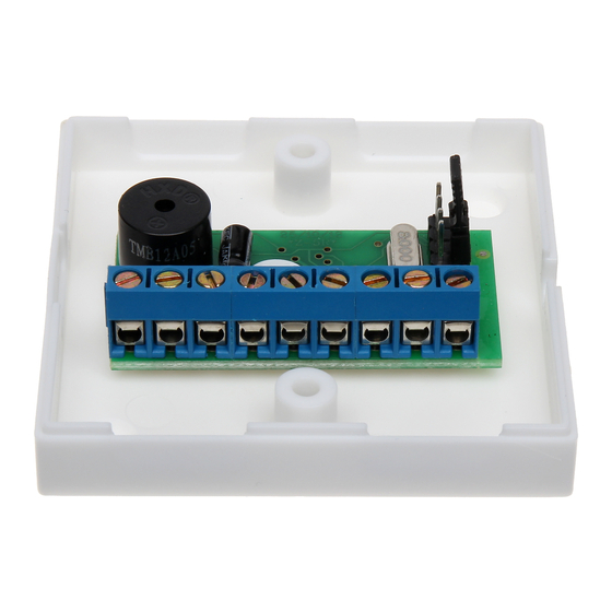
Z-5R Relay Wiegand www.ironlogic.me Figure 1. Controller case dimensions Figure 2. Controller PCB layout Table 1. Terminals designation. Terminal Designation Wiegand interface DATA 1 data bus for reader. Circuiting this terminal to GND activates the iButton inquiry at terminal D0. - Page 3 (ACS Database) must be erased or rewritten. - Card status can be as follows: - Master card is used for Z-5R Relay Wiegand programming only; never is used for access. - Normal (Access) card is used for passing through access point (except when in Blocking Mode).
- Page 4 Z-5R Relay Wiegand www.ironlogic.me 4. PROGRAMMING Important: Before programming the controller, please ensure that a contactor or reader is connected. When describing programming procedures, we will use the term “card touch to the reader”. It means approaching the reader connected to this controller with a card, to a distance that will ensure reliable card ID acquisition (less than 2 cm).
- Page 5 Z-5R Relay Wiegand www.ironlogic.me Table 2. Programming Modes. Modes Activation Legend Programming using Master keys 1…5 – # of touches 1. Add Normal and Blocking Cards 2. Add Master Cards 1m, 1M * Uppercase letter – Long touch (hold 3. Erase Single, Normal and Blocking Cards...
- Page 6 Z-5R Relay Wiegand www.ironlogic.me Mode 2. Add Master Cards (1m, 1M) External reader is connected via iButton protocol. Touch the reader once with a Master card (short touch). On touch, the controller emits a short beep, acknowledging the Master card recognition. Within 6 s, touch and hold the Master card at the reader (long touch).
- Page 7 Z-5R Relay Wiegand www.ironlogic.me programming mode has ended. ake away the Master card now. On next power-up, the controller will automatically enter the programming mode. Note: When the entire database is being erased with a Master card, the programmed Lock Release Time is not reset.
- Page 8 Mode 9. Loading Information from a DS1996L Key into Controller Memory. To load information from a DS1996L key into Z-5R Relay Wiegand controller memory, an iButton (Dallas Touch Memory) key contactor needs to be connected to the reader (see Fig. 5). The database must be already present in the DS1996L key, either previously read from controller memory, or loaded with BaseZ5R software.
- Page 9 Z-5R Relay Wiegand www.ironlogic.me Position #2, CLR (Clear) to erase controller memory. For that, power off the controller, put the jumper into this position and power it on. When everything is erased, a series of short beeps is heard. All keys are erased and programmed door release timer is reset to factory default (3 s).
-
Page 10: Mounting And Connecting
Z-5R Relay Wiegand www.ironlogic.me 6. MOUNTING AND CONNECTING To mount a Z-5R Relay Wiegand Case controller, perform the following steps. 1. Disassemble the case. 2. Mark and drill the mounting holes for the case (as per Fig. 1). 3. Connect the external devices to controller terminals according to the connection layout. -
Page 11: Package Contents
Z-5R Relay Wiegand www.ironlogic.me Figure 6. Connecting external devices 7. PACKAGE CONTENTS - Z-5R Relay Wiegand or Z-5R Relay Wiegand Case Controller:..1 - shunt diode1N5400 or ............1 1N4007 - jumper ....................1 - case (for Z-5R Relay Wiegand Case model only):………..………..1 8. - Page 12 Z-5R Relay Wiegand www.ironlogic.me The symbol of crossed-throught waste bin on wheels means that the product must be disposed of at f separate collection point. This also applies to the product and all accessories marked with this symbol. Products labeled as such must not be disposed of with normal household waste, but should be taken to a collection point for recycling electrical and electronic equipment.
Need help?
Do you have a question about the Z-5R Relay Wiegand and is the answer not in the manual?
Questions and answers