Table of Contents
Advertisement
Advertisement
Table of Contents

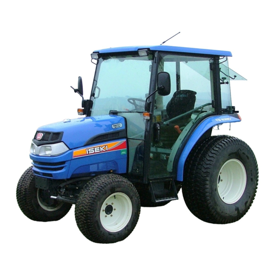
Summary of Contents for Iseki TG5390
- Page 1 I S E K I T R A C T O R S MODELS: TG5390 TG5470 ( HST ASSIST SYSTEM )
-
Page 2: To Our Customer
TO OUR CUSTOMER Thank you very much for purchasing an ISEKI tractor. This operator's manual provides the information necessary for the operation of ISEKI TG tractor which has the HST assist system. Please refer to the operation's manual of standard HST models for ordinary operating and maintenance instructions of tractor. -
Page 3: Table Of Contents
TG5390,5470 TABLE OF CONTENTS TO OUR CUSTOMER ..............................TABLE OF CONTENTS ............................. 1. INSTRUMENTS & CONTROLS - HST TYPE - ...................... HST type ................................INSTRUMENT PANEL ............................Electric Fuel Shut-Off ............................. Main Switch..............................Indicator Light Strip ............................Coolant Temperature Gauge .......................... -
Page 4: Instruments & Controls - Hst Type
INSTRUMENTS & CONTROLS INSTRUMENTS & CONTROLS - HST TYPE - HST type FIG. 1-1 FIG. 1-1: General layout and location of controls within operator’s area on Tractor. Specific use of these controls is given later in this section and also in “Operation” section of this book: Steering Wheel Three Point Hitch Position Control Lever Parking Brake Lever... -
Page 5: Instrument Panel
TG5390,5470 INSTRUMENT PANEL FIG. 1-2: Arrangement of gauges. Control switches and indicators located in instrument panel. Items are detailed in the descriptions that follow: Electric Fuel Shut-Off Turn the main switch to off position so as to stop engine. Main Switch FIG. -
Page 6: Indicator Light Strip
INSTRUMENTS & CONTROLS FIG. 1-4: When main switch, 1, is selected to “GLOW” position, glow indicator, 2, will illuminate after several seconds to indicate the engine combustion chambers are preheated and allow cold engine to be started. Indicator Light Strip FIG. -
Page 7: Coolant Temperature Gauge
TG5390,5470 Coolant Temperature Gauge FIG. 1-6: Gauge, 4, indicates engine coolant tempera- ture when main switch is selected to ON ・ - Shows too cool temperature for severe work. Al- low to warm before applying heavy load. ・ - Indicates overheating. Reduce engine speed to idle, allow to run at no load several minutes and investigate cause (refer to “Troubleshooting”). -
Page 8: Fuel Gauge
INSTRUMENTS & CONTROLS Fuel Gauge FIG. 1-9: Scale, 7, indicates level of diesel fuel in fuel tank when main switch is “ON” NOTE: Use only clean diesel fuel and clean area to pre vent dirt/water entry into fuel tank when refill- ing.DO NOT run out of fuel as bleeding air from the system will be required. -
Page 9: Brakes
TG5390,5470 FIG. 1-12: Turn/hazard indicator lights, 13 and 14, will operate with ROPS-mounted warning lights. This pro- vides operator with easy indication of warning light se- lection. BRAKES Brake Pedals & Parking Brakes FIG. 1-12 FIG. 1-13: Inner brake pedal, 1, and outer brake pedal, 2, independently control the respective left and right wheel brakes, to assist in turning. -
Page 10: Engine Speed Controls
INSTRUMENTS & CONTROLS ENGINE SPEED CONTROLS CAUTION: Always select engine speed to ensure safe operation. Reduce speed prior to turning or reversing Tractor. IMPORTANT: DO NOT “race” or excessively load cold engine. FIG. 1-16: Hand Throttle Lever, 1 - Controls engine speed and will remain in position selected by the opera- tor. -
Page 11: Transmission Shift Lever And Controls (Hst Type)
TG5390,5470 TRANSMISSION SHIFT LEVER AND CONTROLS (HST type) One shift lever is used to select a range of ground travel speed through different gear reductions within the drive train. A hydrostatic control unit (using a control pedal) allows infinitely variable speeds, from zero to top speed, in each range. -
Page 12: Differential Lock Pedal
INSTRUMENTS & CONTROLS DIFFERENTIAL LOCK PEDAL FIG. 1-20: When differential lock pedal, 1, is depressed, HST type both rear axles are locked together to provide equal traction to both rear wheels. This is especially important when operating in loose soil or slippery conditions. Disengage differential lock, by releasing foot pedal. -
Page 13: Lubrication & Periodic Maintenance
TG5390,5470 LUBRICATION & PERIODIC MAINTENANCE Fuse Location (HST Assist type) Main Fuse Box, A- Located on right side, to steering post. Function Turn Lights Head Lights, Tail Lights, Position Light, Horn Stop Light Instrument Panel Alternator, Fuel Pump, Safety Relay... -
Page 14: Troubleshooting
TROUBLESHOOTING TROUBLESHOOTING Please refer to the troubleshooting of standard models for the other problems. HST ASSIST SYSTEM Problem Possible Cause Remedy Sound of horn does not stop Blown fuse Stop the engine. when starting engine. Defective controller Consult your dealer. Defective hydraulic system Defective wiring or sensors Sound of horn does not stop... -
Page 15: Specifications
TG5390,5470 SPECIFICATIONS ENGINE TG5390 TG5470 ake Iseki ..............Iseki Diesel ............Iseki Diesel Model ................E3CDT ..............E4CG Type of Injection, ............Indirect Injection ............ Indirect Injection ...............Overhead Valve ............Overhead Valve Aspiration..............Turbo charger ..............Natural Displacement ..............1498 cm ..............2197 cm Number of Cylinders ..............3 ................4... -
Page 16: Electrical System
SPECIFICATIONS ELECTRICAL SYSTEM System Voltage ........12 volt, negative (-) ground ........12 volt, negative (-) ground Battery cca @ 18 degreesC (0 degreesF) ..630 cca (80D26R) ..........710 cca (115D31R) Charging Except CABIN type ..... 40 amp alternator with internal regulator / rectifier .....40amp alternator with internal regulator / rectifier CABIN TYPE ...... -
Page 17: Check List
TG5390,5470 FACTORY RECOMENDED NEW TRACTOR PRE-DELIVERY INSPECTION CHECK LIST ISEKI USER'S NAME AREA DATE DEALER ADDRESS TRACTOR MODEL SERIAL NO. ENGINE SERIAL NO. COUNTRY THIS PRE-DELIVERY INSPECTION CHECK LIST IS PROVIDED TO IDENTIFY THE CHECKED AND NECESSARY ADJUST BY THE DEALER PRIOR TO DELIVERY OF THIS MACHINE. - Page 18 WIRING HARNESS CABLE WIRING HARNESS CABLE TG5390FH-3, TG5470FH-3 (SHEET A)
- Page 19 TG5390,5470 TG5390FH-3, TG5470FH-3 (SHEET B)
- Page 20 TG5390 TG5470 Overseas Business Division 3-14, Nishi-Nippori, 5-chome, Arakawa-ku, Tokyo 116-8541, Japan Phone: (03) 5604-7658 Fax: (03) 5604-7703 OM-TG5390H3/-EN-10 0807-01-10 Printed in Japan...


Need help?
Do you have a question about the TG5390 and is the answer not in the manual?
Questions and answers