Hikvision ECI-T22Fx Network Turret Camera Quick Start Guide
- Quick start manual (17 pages) ,
- Quick start manual (17 pages)
Advertisement
Appearance Description
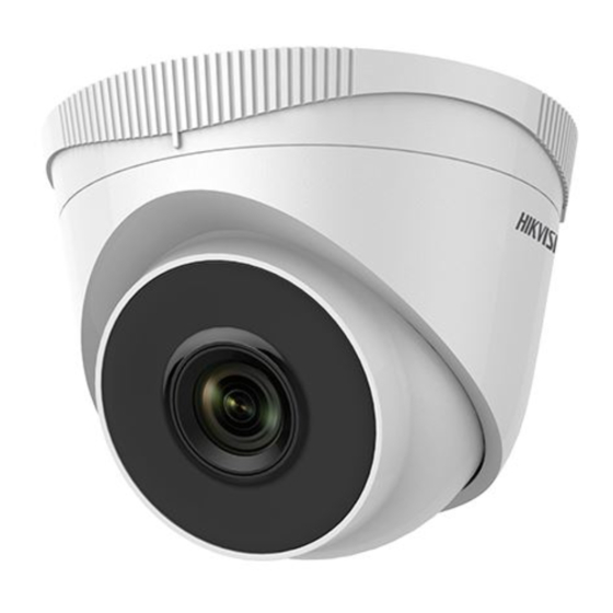
This turret camera appearance is shown as the figures below.

Figure 1-1 Turret Camera Overview
Table 1-1 Type Description
| No. | Description |
| 1 | Enclosure |
| 2 | Camera Body |
| 3 | Mounting Base |
| 4 | Power Cord |
| 5 | Network Cable |
Note:
For cameras that support power over Ethernet (PoE), the power is passed along with data on Ethernet cabling. A switch that supports the PoE function is required.
Installation
Make sure of the following before you start:
- The device included in the package is in good condition and all required parts are included.
- The standard power supply is 12 VDC or PoE (802.3af), and must be consistent with camera requirements.
- Equipment is powered-off during installation.
- The installation environment is correct.
- The wall is strong enough to withstand four times the weight of the camera and bracket.
- There are no reflective surfaces too close to the camera lens. The IR light from the camera may reflect back into the lens and cause reflection.
Note:
Four camera types have the same installation method. We will use the III/IV turret camera as an example to illustrate the installation.
Before you start:
Both wall and ceiling mounting are suitable for the turret camera. Ceiling mounting will be used as an example for this section, and can be used as a reference for wall mounting.
Steps:
- Paste the drill template (supplied) to the desired mounting position on the ceiling.
- Drill the screw holes and the cable hole in the ceiling according to the drill template.
Note:
Drill the cable hole if using the ceiling outlet to route the cable.
![]()
Figure 2-1 The Drill Template - Disassemble the camera.
- Rotate the camera to align the notch with one of the marks.
- Pry the mounting base with a flat object (e.g., a coin) to remove it from the camera body.

Figure 2-2 Disassemble the Camera
- Attach the mounting base to the ceiling with the supplied screws.
Notes:- The supplied screw package contains both self-tapping screws and expansion bolts.
- If the ceiling is made of cement, expansion bolts are required to fix the camera. If the ceiling is made of wood, self-tapping screws are required.

Figure 2-3 Fix the Mounting Base
- Route the cables through the cable hole or side opening.
- Install the camera body back to the mounting base.
![]()
Figure 2-4 Install the Camera Body - Connect the power cord and network cable.
- Power the camera on, and set the network configuration (for details, refer to Network Camera LAN Configuration and Access via Web Browser) to check whether the image is at an optimum angle. If not, adjust the surveillance angle.

Figure 2-5 Adjust Surveillance Angle- Hold the camera body and rotate the enclosure to adjust the pan angle [0° to 360°].
- Move the camera body up and down to adjust the tilt angle [0° to 75°].
- Rotate the camera body to adjust the rotation angle [0° to 360°].


Network Camera LAN Configuration
Note:
The use of products with internet access carries inherent security risks. In order to avoid network attacks and information leakage, strengthen your own network protection.
If the product does not work properly, contact your dealer or the nearest service center for help.
Wiring
Connect the camera to the network as follows:

Figure 3-1 Connect Directly

Figure 3-2 Connect via a Switch or a Router
Activate the Camera
Activate the camera by setting a strong password. Activation via web browser, activation via SADP, and activation via client software are supported. Activation via SADP software and web browser will be used as examples to introduce camera activation.
Note:
Refer to the Network Camera User Manual for activation via client software.
Activation via Web Browser
Steps:
- Power the camera on. Connect the camera to your computer or the switch/router that your computer connects to.
- Input the IP address into the address bar of the Web browser, and press Enter to enter the activation interface.
Notes:- The camera's default IP address is 192.168.1.64.
- The computer and the camera should belong to the same subnet.
- For cameras that have DHCP enabled by default, use the SADP software to search for the IP address.
")
Figure 3-3 Activation Interface (Web)
- Create and input a password.
![caution]() STRONG PASSWORD RECOMMENDED – We highly recommend creating a strong password of your own choosing (using a minimum of eight characters, including upper case letters, lower case letters, numbers, and special characters) in order to increase the security of your product. We recommend regularly resetting your password on a weekly or monthly basis, especially in high security systems.
STRONG PASSWORD RECOMMENDED – We highly recommend creating a strong password of your own choosing (using a minimum of eight characters, including upper case letters, lower case letters, numbers, and special characters) in order to increase the security of your product. We recommend regularly resetting your password on a weekly or monthly basis, especially in high security systems. - Confirm the password.
- Click OK to save the password and enter the live view interface.
")
 STRONG PASSWORD RECOMMENDED – We highly recommend creating a strong password of your own choosing (using a minimum of eight characters, including upper case letters, lower case letters, numbers, and special characters) in order to increase the security of your product. We recommend regularly resetting your password on a weekly or monthly basis, especially in high security systems.
Activation via SADP Software
SADP software is used for detecting online devices, activating cameras, and resetting passwords.
SADP can be obtained from the supplied disk or the official website, and installed by following the prompts.
Follow the steps to activate the camera.
Steps:
- Run SADP to search for online devices.
- Check the device status from the device list, and select the inactive device.

Figure 3-4 SADP Interface
Note:
SADP supports batch camera activations. Refer to the SADP user manual for further details. - Create, input, and confirm the password.
![caution]() STRONG PASSWORD RECOMMENDED – We highly recommend creating a strong password of your own choosing (using a minimum of 8 characters, including upper case letters, lower case letters, numbers, and special characters) in order to increase the security of your product. We recommend regularly resetting your password on a weekly or monthly basis, especially in high security systems.
STRONG PASSWORD RECOMMENDED – We highly recommend creating a strong password of your own choosing (using a minimum of 8 characters, including upper case letters, lower case letters, numbers, and special characters) in order to increase the security of your product. We recommend regularly resetting your password on a weekly or monthly basis, especially in high security systems.
Note:
You can enable the Hik-Connect service for the device during activation. Refer to Chapter 5.1 for detailed information. - Click Activate to start activation.
You can check whether the activation is complete in the popup window. If activation failed, make sure that the password meets the requirements, and try again.

Modify the IP Address
Purpose:
To view and configure the camera via LAN (Local Area Network), you need to connect the network camera in the same subnet as your PC.
Use the SADP software or client software to search and change the IP address of the device. IP Address modification via SADP software will be used as an example.
In order to modify the IP address via client software, refer to the user manual of the client software.
Steps:
- Run SADP.
- Select an active device.
- Change the device IP address to the same subnet as your computer by either modifying the IP address manually, or by checking the Enable DHCP checkbox.
![]()
Figure 3-5 Modify the IP Address
Note:
Hik-Connect can be enabled during activation. Refer to Chapter 5.1 for detailed information. - Input the admin password and click Modify to complete IP address modification.
SADP supports batch IP address modification. Refer to the SADP user manual for details.

Access via Web Browser
System Requirement:
Operating System: Microsoft Windows XP SP1 and above
CPU: 2.0 GHz or greater
RAM: 1 Gb or greater
Display: 1024×768 resolution or higher
Web Browser: Internet Explorer 8.0 or higher, Apple Safari 5.0.2 or higher, Mozilla Firefox 5.0 or higher, and Google Chrome 18 or higher
Steps:
- Open the Web browser.
- In the browser address bar, input the IP address of the network camera, and press the Enter key to enter the login interface.
Note:
The default IP address is 192.168.1.64. It is suggested that you change the IP address to the same subnet as your computer. - Input the user name and password.
The admin user should configure the device accounts and user/operator permissions properly. Delete the unnecessary accounts and user/operator permissions.
Note:
The device IP address gets locked if the admin user performs 7 failed password attempts (5 attempts for the user/operator). - Click Login.

Figure 4-1 Login Interface - Install the plug-in before viewing the live video and managing the camera. Follow the installation prompts to install the plug-in.
Note:
You may have to close the web browser to complete plug-in installation.
![]()
Figure 4-2 Download Plug-in - Reopen the web browser after plug-in installation and repeat steps 2 to 4 in order to login.
Note:
For further configuration instructions, please refer to the network camera user manual.


Hik-Connect
Purpose:
Hik-Connect is a mobile application to view live camera images, receive alarm notifications, etc.
Enable Hik-Connect for Use with Cameras
Purpose:
Enable Hik-Connect should on your camera before using the service.
You can enable the service either via SADP software or a Web browser.
Enable Hik-Connect Service via SADP Software
Steps:
- Check the Enable Hik-Connect checkbox:
- For the "Activate the Device" page that appears during camera activation, refer to Chapter 3.2.2.
- For the "Modify Network Parameters" page that appears while modifying the IP address, refer to Chapter 3.3.
- Create or change the verification code.

Figure 5-1 Verification Code Setting (SADP)
Note:
The verification code is required when adding the camera to Hik-Connect. - Click and read the "Terms of Service" and "Privacy Policy."
- Confirm the settings.

Enable Hik-Connect via a Web Browser
Before You Start:
Activate the camera before enabling the service. Refer to Chapter 3.2. for more information.
Steps:
- Access the camera via the Web browser. Refer to Chapter 4.
- Enter the platform access configuration interface, as follows: Configuration > Network > Advanced Settings > Platform Access.

Figure 5-2 Platform Access Configuration (Web) - Set the Platform Access Mode to Hik-Connect.
- Check the Enable checkbox.
- Click and read the "Terms of Service" and "Privacy Policy" in the pop-up window.
- Create or change the verification code for the camera.
Note:
A verification code is required when you add the camera to Hik-Connect. - Save the settings.

Add Camera to Hik-Connect
Before You Start:
Enable Hik-Connect on the camera before adding it to your Hik-Connect account. See Chapter 5.1.
Steps:
- Use a network cable to connect camera to a router if the camera does not support Wi-Fi.

Figure 5-3 Connect a Router


Documents / ResourcesDownload manual
Here you can download full pdf version of manual, it may contain additional safety instructions, warranty information, FCC rules, etc.
Download Hikvision ECI-T22Fx Network Turret Camera Quick Start Guide
Advertisement


Need help?
Do you have a question about the ECI-T22Fx and is the answer not in the manual?
Questions and answers