Advertisement
Quick Links
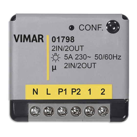
SMART SWITCH
01798
EnOcean actuator with 2 relay outputs NO 5 A 230 V~, 2 programmable inputs
with 1-way switch function for local control, 230 V~ 50/60 Hz power supply.
The actuator with EnOcean module is designed to receive the radio control from the radio
frequency rocker button to actuate the connected loads via the relay outputs. It can also be
connected to two 1-way switches/push buttons to control loads also locally. With its compact
dimensions, the actuator can be installed anywhere on the wall (retrofit inside of the flush
mounting box) or on the ceiling (false ceiling, etc.).
In the event of a power failure, once the mains power supply is restored, the actuator
keeps the previous configuration.
TECHNICAL CHARACTERISTICS.
• Power supply: 230 V~, 50 Hz.
• Switching capacity: 230 V~ - 5 A
• Self-consumption: <1W
• Frequency range: 868.3 MHz
• Frequency band occupied: from 868.0 to 868.6 Mhz
• Max. RF power: +3dBm
• Range: up to 30 metres
• Possibility of connecting two 1-way switches/push buttons
• Operating temperature: 0 - 35 °C
• Maximum number of radio transmitters that can be stored: 22
• RGB LED for signalling the various configuration phases
• EEP (Profile EnOcean®): D2-01-12
• Dimensions: 40 mm x 44 mm x 16.9 mm
• Weight: 34 g
CONTROLLABLE LOADS.
• For each relay output:
- resistive loads
: 5 A (20.000 cycles);
- incandescent lamps
: 5 A (20.000 cycles);
- fluorescent lamps
: 50 W (20.000 cycles);
- LED lamps: 50 W (20.000 cycles).
INSTALLATION.
• Installation of two 1-way switches/push buttons and 2 lamps. By default all wired 1-way
switches connected to the actuator work as "switch" ("two-way switch") with EnOcean®
transmitters associated with the device.
• Identification of configuration of both 1-way switches/push buttons. When powering up the
actuator after configuration, press the 1-way switch it is connected to only once. An automatic
identification procedure will be run to identify if a one-position stable or two-position stable
1-way switch is being used.
Note 1: The same configuration applies to both 1-way switch/push button 1 and 1-way switch/
push button 2. The devices connected to actuator 01798 must be the same type (in other
words two one-way switches or two push buttons and never one one-way switch and one
push button). To run the automatic identification again manually reset the device.
Note 2: When using radio controls, we recommend you use the device only with the push
buttons and not with the 1-way switches.
CONFIGURATION.
ACTUATOR OPERATING MODES
• LOCAL CONTROL. It is possible to switch the device on or off locally with a short press of
the CONF push button. This switches both outputs at the same time. Alternatively, operate
the switches/push buttons connected to the device to turn the light on/off on CHANNEL 1 or
2.
• ASSOCIATION. Two procedures are available (1 or 2) to access association mode; for both,
one of the two channels available is associated at a time. The actuator must be powered and
the lights off.
CHANNEL 1 ASSOCIATION
1. Using the actuator: press the CONF button three times (in less than 1 s).
2. Using the wired 1-way switches/push buttons: press the CHANNEL 1 1-way switch/push
button 3 times (in less than 1 s).
The LED flashes red and the light relating to 1-way switch/push button 1 flashes to indicate
that CHANNEL 1 is in association/disassociation mode; quickly (< 1 s) press the button you
wish to associate, which will control light 1, within 30 s.
CHANNEL 2 ASSOCIATION
1. Using the actuator: press the CONF button three times (in less than 1 s); wait 1 s and press
the CONF button again.
2. Using the wired switches/push buttons: Press the CHANNEL 2 1-way switch/push button
3 times (in less than 1 second).
The LED flashes red and the light relating to 1-way switch/push button 2 flashes to indicate
that CHANNEL 2 is in association/disassociation mode; quickly (< 1 s) press the button you
wish to associate, which will control light 2, within 30 s.
To associate a transmitter, see paragraph Procedure for association as receiver; the LED
lights up in green to confirm the association procedure. If during the "Association mode" the
LED flashes orange it means that the actuator memory is full or that, during the procedure, no
transmitter has been associated. If the memory is full delete a transmitter and then associate
the new one.
01798 EN 01 2301
• LED INDICATIONS DURING "LEARNING MODE".
"Learning mode" PHASES
Access to "Learning mode"
Device enrolled
Deletion of enrolled device
Interruption of "Learning mode"
Error during "Learning mode"
Memory full (22 devices exceeded)
"Learning mode" time-out
• DEVICE RESET. Press CONF for more than 5 s until the LED turn on orange; when the
button is released the LED remains on and you are in "Reset Mode". Press CONF once to
reset; the LED flashes red and green to confirm the operation. In "Reset Mode" the button
must be pressed within 30 s after which, if no operations are performed, the LED stops
flashing and no reset is run.
PROCEDURE FOR ASSOCIATION AS RECEIVER.
• EnOcean® Switch, Type "rocker button control" (EEP: F6-02-01).
To associate this transmitter to the actuator proceed as follows:
1. Activate the "Association mode" on the device.
2. Press any button on the radio control. The button pressed during the association process
is the one that activates the selected channel while the other button switches off the selected
channel. For example:
Association
mode
Associated button
during the
"Association
mode"
Repeat the procedure for both channels.
To delete the association of a transmitter, activate "Association mode" on the related channel
(1 or 2) and press any button on the transmitter; the device will no longer be able to control
the selected channel of the actuator 01798. To delete both channels, repeat the procedure
for each one.
PROCEDURE FOR ASSOCIATION AS TRANSMITTER.
When the switches are connected to inputs P1 and/or P2 they can operate as EnOcean®
transmitters; once configured, via actuator 01798, they can control any other EnOcean®-
compatible receiver.
To associate actuator 01798 to another receiver proceed as follows:
1. Activate the "Association mode" on the receiver.
2. Press the button on the connected switch to be associated to the receiver once.
At the end of the association procedure, the state (ON or OFF) of the output on actuator 01798
determines the "ON" state of the associated receiver.
Example.
If you want the receiver to be synchronised with the actuator, associate the button by moving
the output to ON; vice versa, if you don't want the receiver to be synchronised, associate the
button by switching the output to OFF.
To delete the association of actuator 01798 from another receiver activate the "Association
mode" on the receiver and press the button on the switch associated to the receiver once.
SUPPORTED PROFILES (EEP)
F6-02-01
F6-04-01
F6-10-00
A5-07-02
A5-07-03
A5-08-01
A5-10-19
A5-10-18
A5-10-1A
A5-10-1D
A5-10-01
A5-10-05
A5-10-10
A5-10-13
A5-10-16
A5-10-0B
A5-14-01
A5-14-02
LED INDICATORS
1 GREEN flash then turns to RED
2 GREEN flashes
2 RED flashes
2 RED flashes
2 RED flashes
2 ORANGE flashes
2 ORANGE flashes
Use
Button pressed
State of
on the
actuator
transmitter
01798
ON
OFF
ON
OFF
ON
OFF
ON
OFF
D5-00-01
A5-07-01
A5-08-02
A5-08-03
A5-10-1B
A5-10-1C
A5-10-08
A5-10-0C
A5-10-17
A5-10-0A
A5-14-03
A5-14-04
Viale Vicenza, 14
36063 Marostica VI - Italy
www.vimar.com
Advertisement

Related Manuals for Vimar 01798


Summary of Contents for Vimar 01798
- Page 1 The LED flashes red and the light relating to 1-way switch/push button 1 flashes to indicate At the end of the association procedure, the state (ON or OFF) of the output on actuator 01798 that CHANNEL 1 is in association/disassociation mode; quickly (< 1 s) press the button you determines the “ON”...
- Page 2 RED Directive. Standards EN 60669-2-1, EN 300 220-2, EN 301 489-3, EN 62479. Vimar SpA declares that the radio equipment complies with Directive 2014/53/EU. The full text of the EU declaration of conformity is on the product sheet available on the following website: www.vimar.com...
Need help?
Do you have a question about the 01798 and is the answer not in the manual?
Questions and answers