Table of Contents

Related Manuals for ELABO 90-4F


Summary of Contents for ELABO 90-4F
- Page 1 DIN EN ISO 9001 certified ELABO after sale service: Calibration at ELABO factory Calibration at customer premises Test units on loan Hotline ++49 7951/307-0 ELABO GmbH D-74564 Crailsheim Operating manual PE conductor tester 90-4F...
-
Page 2: Table Of Contents
PE-Conductor Tester 90-4F Description DESCRIPTION OF FRONT PANEL CONTROLS ........3 INTRODUCTION ..................5 GENERAL INFORMATION ..............5 ABBREVIATIONS AND SYMBOLS ............6 SHORT DESCRIPTION OF THE PE CONDUCTOR TESTER ....6 GENERAL DATA ..................7 NAME PLATES ..................7 SAFETY REGULATIONS ................ -
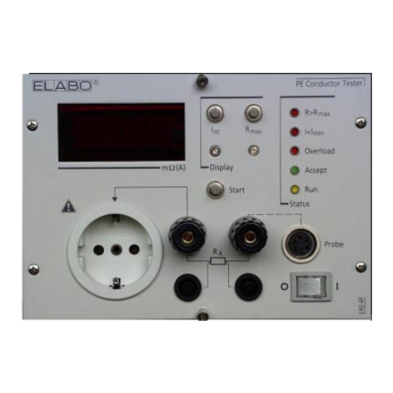
Page 3: Adescription Of Front Panel Controls
PE-Conductor Tester 90-4F Description DESCRIPTON OF FRONT PANEL CONTROLS Front panel S2 S4 R2 S3 R1 X3.2 X4.2 X4.1 X3.1 S1/H1 Rear side contact 1 / 3 X6-3 X6-1... - Page 4 PE-Conductor Tester 90-4F Description DESCRIPTON OF FRONT PANEL CONTROLS N . o N . o N . o N . o ..v i t u l l c t i...
-
Page 5: Introduction
If you have any questions after reading the operating instructions the ELABO Hot -line (Telephone 07951/307-0) is at your disposal for further details. For better use of the operating instructions the cover page can be opened out. -
Page 6: Abbreviations And Symbols
Reference for the effective and economic mode of operation - Chap. 2.1 1.3 SHORT DESCRIPTION OF THE PE CONDUCTOR TESTER The measuring instrument 2GA27 90-4F serves for the testing of the efficacy of the PE conductor connection, for electrical devices for measurement, controlling and laboratory... -
Page 7: General Data
230 V +10% -5%/ 49 to 61 Hz Dimensions: Euro-Subdrawer 3 HU/36 pitches. Depth 196 mm Weight: 6 kg 1.5 NAME PLATES ELABO PE-Conductor Tester 90-4F . Nennspg. V 230 V ; 49 - 61 Hz Nennstrom A 1.2 A 90-4F... -
Page 8: Safety Regulations
The tester may be operated by trained and skilled staff only. ELABO has equipped the unit with all necessary safety devices when using them as per the specifications in order to protect the operator from appearing risks. -
Page 9: General Rules Of Conduct And Safety Regulations
Unauthorized modifications at the device as well as the use of spare parts, accessories and extra equipments which have not been controlled and released by ELABO can have a negative influence on the function and features of the device. ELABO does not accept any liability for damages resulting from this. -
Page 10: Particular References To The Pe Conductor
PE-Conductor Tester 90-4F 2. Safety regulations 2.5 PARTICULAR REFERENCES TO THE PE CONDUCTOR TESTER Before opening the unit pull out power supply plug! Switching off by means of rocker switch (S1/H1) is insufficient! The PE contact of the safety socket outlet is not connected to PE... -
Page 11: Putting Into Operation
The unit is designed to be operated in a suitable rack. As an option is a housing available for application as stand-alone-unit (ELABO-accessory: Catalogue-No. 2GA27 30-6M). The unit must not be operated outside a rack or housing. -
Page 12: Setting The Test Unit Parameters
PE-Conductor Tester 90-4F 3. Putting into operation 3.3 SETTING THE TEST UNIT PARAMETERS Before the unit is put into operation some parameters must be adjusted. Switch on unit with illuminated rocker switch (S1/H1). The pilot lamp (S1/ H1) lights up. - Page 13 PE-Conductor Tester 90-4F 3. Putting into operation Buzzers as GO - or FAULT - signal. Jumper > FAULT-signal > Go-signal Buzzer ON or OFF. Jumper > open > Buzzer for timer mode or Go/Fault evaluation Jumper > Timer mode >...
-
Page 14: Operating Modes
PE-Conductor Tester 90-4F 4 Operating modes 4. OPERATING MODES Before starting of the measuring operation the adjustments must be carried out according to Chap. 3.3. 4.1 MEASURING PRINCIPLE Illustration 4.1 shows the measuring principle of the PE conductor tester. Sensor... -
Page 15: Protective Conductor Test Without Safety Plug
PE-Conductor Tester 90-4F 4 Operating modes 4.2 PROTECTIVE CONDUCTOR TEST WITHOUT SAFETY PLUG Ills. 4.2 shows the test arrangement for this operating mode. test point test object PE-contact Fig. 4.2: Test arrangement for measurements without safety plug For the connection of the item on test to the terminals of the instrument use connecting leads with a cable cross-section of at least 2.5 mm²... -
Page 16: Test With Safety Plug
PE-Conductor Tester 90-4F 4 Operating modes 4.3 TEST WITH SAFETY PLUG Fig. 4.3 shows the test arrangement for the measurement with a safety plug. test point test object PE-contact Fig. 4.3: Test arrangement for measurements with safety plug Use a power supply cable with a cable cross-section of at least 1 mm² for the connection of the item on test to the socket outlet of the instrument! Put the power supply cable of the item on test into the socket outlet (X2). -
Page 17: Test With Test Probe
4.4 TEST WITH TEST PROBE For a simpler operation the measuring instrument can be operated with a test probe. (ELABO - accessory: Catalogue-No. 2GA27 94-4S). Fig. 4.4 shows the test arrangement with a test probe and without a three wire plug. -
Page 18: Operation In Combination With An Insulation
4 Operating modes 4.5 OPERATION IN COMBINATION WITH AN INSULATION TESTER Together with the ELABO-Insulation tester (Catalog-No. 2GA27 90-2E) a simultaneous measurement of PE conductor and insulation resistance is possible. Consider for the connection of the item on test absolutely the references given in Chap. -
Page 19: Operation Via Interface
PE-Conductor Tester 90-4F 5 Interface OPERATION VIA INTERFACE The PE conductor tester disposes of an interface which enables the external control and evaluation. The signal level of the input should be between 5 V and 24 V. The connections a and c of 64 pole terminal strip (X7) are linked. - Page 20 PE-Conductor Tester 90-4F 5 Interface Pin 8 Measuring H. Applying of an external DC of 5 V to 24 V, acts like operating key „Start“ (S2). For more information see Chapt. 9.2 Appendix. Pin 16, 18 Fault I Floating relay output for identifying off-limit test currents.
-
Page 21: Terminal Assignment Of The 11-Pin Vg Connector (X1)
PE-Conductor Tester 90-4F 5 Interface 5.2 TERMINAL ASSIGNMENT OF THE 11-PIN VG CONNECTOR (X1) The 11 pin VG multiple connector is connected as follows. Pin 5 Mains supply Pin 20 Mains supply Pin 32 Protective conductor connection Pin 26 Insulation test voltage (negative potential). -
Page 22: Fault Indications
PE-Conductor Tester 90-4F 6 Fault indicatons FAULT INDICATIONS For tests according to Chap. 4 the following fault indications can occur on the test unit. The red LED FAULT (V3) lights up. The measured PE conductor resistance is above the preset R . -
Page 23: Maintenance And Attendance
If it happens that a fuse blows it may be exchanged only once. If the interruption of the current circuit occurs once again after the fuse has been replaced, please send the unit to your next ELABO-service or contact the ELABO-hot-line (0049 7951/307-0). -
Page 24: Service Of The Housing
In case you required spare parts (fuses, keys, code plugs,...) for your test unit, please contact the ELABO-Service or the ELABO-hot-line (0049 7951/ 307-0. We will be glad to be of help to you. -
Page 25: Technical Data
PE-Conductor Tester 90-4F 8. Technical data TECHNICAL DATA Type of test: reference EN 61010 (VDE0411), EN60335 (VDE0700), EN60950 (VDE 0805) Duty cycle: 10 %, max. operating time 1,5 min. Output voltage: max. 10V AC Test current : 10 ... 25 A... -
Page 26: Appendix
PE-Conductor Tester 90-4F 9 Appendix APPENDIX In the appendix you will find the component location illustration of the PC-boards and the wiring diagrams for the combined operation of the PE conductor tester with the insulation tester 90-2E. Fig. 9.1 shows the subassemblies of the unit. -
Page 27: Component Location Illustration Of Subassembly
PE-Conductor Tester 90-4F 9 Appendix 9.1 COMPONENT LOCATION ILLUSTRATION OF SUBASSEMBLY PE200 / PE300 Fig. 9.2 shows the component location illustration of the subassembly PE200 (see Chap. 7.1). Main fuse F1 Fig. 9.2: Component location illustration PE200 Ills. 9.3 shows the component location illustration of the subassembly PE300. -
Page 28: Component Location Illustration Of Subassembly
PE-Conductor Tester 90-4F 9 Appendix 9.2 COMPONENT LOCATION ILLUSTRATION OF SUBASSEMBLY PEIS200 Fig. 9.4 shows the subassembly PEIS200 (see Chap. 3.3). Fig 9.4: Component location illustration PEIS200 Comment on the jumper fields of subassembly PEIS 200. At the subassembly PEIS200 the following setting can be performed by jumpers. - Page 29 PE-Conductor Tester 90-4F 9 Appendix Buzzer for Timer mode or Go-/Fault evaluation. Jumper > Timer mode > Fault evaluation Start H. Jumper > Start H not as floating intput > Start H as floating input ATTENTION: Only possible if B9 2-3 is set and GND ext. is connected to St1/04 ac GNDR.
-
Page 30: Wiring Diagram
PE-Conductor Tester 90-4F 9 Appendix 9.3 WIRING DIAGRAMM Fig. 9.4: Diagram - 64- and 11pole. VG-terminal PE-tester 90-4F... - Page 31 ELABO GmbH VO15-55_ EU-Konformitätserklärung Roßfelder Straße 56 D-74564 Crailsheim EU-Declaration of Conformity Tel.: +49 7951 307-0 Fax: +49 7951 307-66 info@elabo.de www.elabo.de Hiermit erklären wir in alleiniger Verantwortung, dass das Produkt We declare under our sole responsibility that the product Bezeichnung des Produkts: PE Messgerät...
- Page 32 Copyright - ELABO GmbH This print is only destined for the recipient of the unit and has to be used for the intended purpose only. The operating instructions must in no way completely or partly be copied or translated in other languages without a written permission.
Need help?
Do you have a question about the 90-4F and is the answer not in the manual?
Questions and answers