Table of Contents
Advertisement
Quick Links
Advertisement
Table of Contents

Related Manuals for ELABO 92-4A


Summary of Contents for ELABO 92-4A
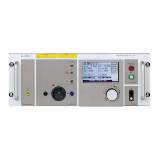
- Page 1 Operating manual Leakage current tester 92-4A / 92-4D / 92-4E...
-
Page 2: Table Of Contents
Leakage current tester 92-4A / 92-4D / 92-2E Content INTRODUCTION ............... 7 General information ..............7 Abbreviations and symbols ............8 Brief description of the tester ............. 8 Technical main data ..............10 Name plate ................10 SAFETY REGULATIONS ............11 Signs of safety and warning regulations ........11... - Page 3 SPECIFICATIONS ..............60 Leakage current tester 92-4A ..........60 Leakage current tester 92-4D / 92-4E ........61 TESTER INSIDE ..............63 1-phase devices 92-4A, - 4E; - 4G ......... 63 I.ii 3-phase device 92-4G ............. 64 MEASURING CIRCUITS ............65 II.i...
- Page 4 Leakage current tester 92-4A / 92-4D / 92-2E MODIFICATIONS ..............72 IV.i External supply via multiple connector ........72 IV.ii Test unit with automatic voltage regulation (optional feature) . 73 MEASUREMENT SYSTEM ............. 74 BASIC TEST MODES ............75 VI.i Basic test modes to EN 60601..........75 VI.ii...
- Page 5 Leakage current tester 92-4A / 92-4D / 92-2E F2 X5 S2/HA2 S3/H3 S1/H1 X3.1 X2 X3.2 X3.3 X4.1 X4.2 X4.3 F3 X7 X8 X9 X10 X11 X12...
- Page 6 Leakage current tester 92-4A / 92-4D / 92-2E Equipment Function Display Graphic display 240x 128 Pixel indication of menu and measurement values S1/H1 Switch / glow lamp Mains switch with indication lamp Automatic circuit breaker 15 A Output fuse, power supply of test object...
-
Page 7: Introduction
If you have any questions after reading the operating instructions the ELABO HOT-LINE (Telephone +49 7951/307-202) is at your disposal for further details. For better use of the operating instructions the cover page can be opened out. -
Page 8: Abbreviations And Symbols
There are manually or automatically test runs possible. For storage of test parameters it is possible to create parameter blocks. Maximal 200 different parameter blocks can be stored. The unit can either be controlled via the front panel components or the interface (CAN-Bus or RS232-interface) by using a PC. To this, ELABO... - Page 9 The commands for the control of the device contains the description of the remote control of the 92-4A / -4D / -4E. The description of the menus is helpful for the programming of the remote control of the device.
-
Page 10: Technical Main Data
Supply (internal/external): see Chapt. 9 "SPECIFICATION" Name plate ELABO Leakage current tester 92-4A / 92-4D / 92-4E The name plate is located on the rear panel of the tester. 230 V ; 49 - 61 Hz Nennspg. V 16.0 A... -
Page 11: Safety Regulations
When operating the tester voltages up to 300 V can occur. In dealing with voltage there is danger to life ! Therefore ELABO has equipped the testing units with all necessary safety devices when using them as per the specifications in order to protect the operator from appearing risks. -
Page 12: Use As Per Specifications And Exclusion Of Liability
ELABO does not accept any liability for damages resulting from this. ELABO does not accept any liability for damages arising by non-ob-... -
Page 13: Further Notes
Leakage current tester 92-4A / 92-4D / 92-2E Safety Regulations The operating instructions have to be always available at the operational place of the tester. Incomplete or illegible operating instructions have to be replaced immediately. Of course, we are pleased to be of help to you in this respect. -
Page 14: Make Ready
Leakage current tester 92-4A / 92-4D / 92-2E Make ready MAKE READY Transport and installation The device is delivered completely packed and may only be taken out off the package directly at the operational place. If an intermediate storage is necessary, a dry storage place must be chosen. -
Page 15: Ac Power Supply
Leakage current tester 92-4A / 92-4D / 92-2E Make ready The operation of the unit without being fastened is not permitted! The unit should not be operated without being put into an enclosure or rack. AC power supply The power supply of the unit is by means of a three pin plug. -
Page 16: Connection For External Supply Of Test Object
Leakage current tester 92-4A / 92-4D / 92-2E Make ready Connection for external supply of test object The connection for an external supply is carried out by means of safety lab terminals X4.1, X4.2 and X4.3 located at the rear of the unit. External supply: 50 ... 280 V / 50 ... 400 Hz, fusing 15 A. The connection principle is represented flowingly. Note: The PE-connection has to be connected to the appropriate reference potential. -
Page 17: Connection Of The Interfaces
Leakage current tester 92-4A / 92-4D / 92-2E Make ready Connection of the interfaces 3.6.1 Connection of the CAN-interface (Option) Plug in the CAN-BUS-interface cable into the 9pole D-SUB-jack X13. The next user in the bus system must be connected to X14. If the control shall be carried out via the CAN-interface then the parameter of the interface must be set in the menu to " Equipment settings" CAN-Bus. -
Page 18: Switch On
Leakage current tester 92-4A / 92-4D / 92-2E Make ready Switch on Prerequisite: The device is connected according to chapter 3.4 or 3.5. • Operate the switch S1 to position "I". The mains pilot lamp H1 lights up and the display shows after a short... -
Page 19: Display Division General
Leakage current tester 92-4A / 92-4D / 92-2E Make ready • Switch on the unit. Mains switch S1 to "Position I" (see above). Status line: Error message Illustr. 3.6: Error message of incorrect mains plug Display division general Section for action keys in the test menus... -
Page 20: Password Protection
Leakage current tester 92-4A / 92-4D / 92-2E Make ready Password protection The device includes a 3-layer password protection function. The pass- word layers are separately from each other to activate or to deactivate. The passwords for the layers are individually set able. -
Page 21: Change Language
Leakage current tester 92-4A / 92-4D / 92-2E Make ready 3.10 Change language Language setting for the display menu. Illustr. 3.9: Change language • Select the menu item "Select language" (rotary encoder S4) and confirm by pressing to S4. • Turn the rotary encoder S4 until the required language is displayed (see above). -
Page 22: Menu System
Leakage current tester 92-4A / 92-4D / 92-2E MENU SYSTEM MENU SYSTEM General 4.1.1 Move cursor The menu is operated exclusively by the rotary encoder S4. Turn the rotary encoder left. The cursor moves to the left or upwards. Turn the rotary encoder right. The cursor moves to the right or downwards. -
Page 23: Main Menu
Leakage current tester 92-4A / 92-4D / 92-2E MENU SYSTEM Main menu Illustr. 4.2: Main menu Manual test - Chapt. 4.3 and 5.2 Manual test of individual test steps or combination. Automatic test - Chapt. 4.4 and 5.3 Fully automatic test run of a leakage test e.g. GLC / ELC / PLC or PAC. -
Page 24: Menu Manual Test
Leakage current tester 92-4A / 92-4D / 92-2E MENU SYSTEM Menu Manual test Manuell Manual In the menu „Manual Test“ every single basic test step can explicitly be selected and executed. The initial settings of the test are saved in the selected parameter block. The menu serves principally for creating and testing new test data (type sample test). -
Page 25: Menu Automatic Test
Leakage current tester 92-4A / 92-4D / 92-2E MENU SYSTEM Menu Automatic test Auto For automatic tests the measuring steps are carried out in consequence automatically. The initial settings of the test are saved in the selected pa- rameter block. The number of executed measuring steps depends on the pre-set test mode and further parameters. -
Page 26: Menu Set Test Parameters
Leakage current tester 92-4A / 92-4D / 92-2E MENU SYSTEM Menu Set test parameters Param In this menu the initial setting for the leakage current measurement is carried out. Depending on the measurement configuration you have se- lected, there maybe not all of the following parameters available or cannot be edited. -
Page 27: Basic Settings
Leakage current tester 92-4A / 92-4D / 92-2E MENU SYSTEM 4.5.1 Basic settings Device In this menu the basic setting of the parameter block is carried out. Depending on the measurement configuration you have selected, there may be not all of the following parameters available or cannot be edited. - Page 28 Leakage current tester 92-4A / 92-4D / 92-2E MENU SYSTEM supply voltage is not activated. Mind the correct connection of the external supply! Mains supply check "no max./max +20%" - Monitoring of the supply voltage (at supply internally or externally). For test objects with auto- matic voltage regulation the adjustment of the output voltage is set with a tolerance of +3 V.
- Page 29 Leakage current tester 92-4A / 92-4D / 92-2E MENU SYSTEM Warm-up time "00:00:00" hh:mm:ss - depending on the test conditions varying warm-up times can be defined. The item under test will then, before the test, each test step etc., be applied to the operating voltage (warm up phase). If "0" is entered the function is not active.
- Page 30 Leakage current tester 92-4A / 92-4D / 92-2E MENU SYSTEM Illustr. 4.9: Menu - Base settings III...
-
Page 31: Parameter Of Leakage Current Measuring
Leakage current tester 92-4A / 92-4D / 92-2E MENU SYSTEM 4.5.2 Parameter of Leakage Current Measuring Test In this menu the setting is carried out for the leakage current measurement. Depending on the measurement configuration you have selected, there maybe not all of the following parameters available or cannot be edited. The entered values are changed in the at the moment active parameter block. - Page 32 Leakage current tester 92-4A / 92-4D / 92-2E MENU SYSTEM PAC - Patient Auxiliary Current - Measurement of the auxiliary Optional feature current generated by the application part of the IUT which flows expansion board 92-4R Z11 for electro through the patient. Application for medical equipment only, according to EN 60601-1. medicine EN 60601-1 PLC - Patient Leakage Current "B / BF / CF"...
- Page 33 Leakage current tester 92-4A / 92-4D / 92-2E MENU SYSTEM For medical equipment (EN60601-1) it is distinguished for the limit value of the leakage current between " NC " (Normal Condition) and " SFC " (Single Fault Condition). For other regulations there is only one limit value mentioned.
- Page 34 Leakage current tester 92-4A / 92-4D / 92-2E MENU SYSTEM Peak value measurement: Auto / 10 mA - the measuring starts at the highest measure- ment range downwards to the lower ranges. Electric burn effect of touch currents and measurements according...
-
Page 35: Select Parameter Block
Leakage current tester 92-4A / 92-4D / 92-2E MENU SYSTEM 4.5.3 Select Parameter Block Select A stored parameter block can be loaded. Select the number of the pa- rameter block with rotary encoder S4. The display shows the name of parameter block. -
Page 36: Erase Parameter Block
Leakage current tester 92-4A / 92-4D / 92-2E MENU SYSTEM 4.5.5 Erase Parameter Block Erase The device deletes the actual parameter block after inquiry. The memory position number is released. Note: Erased parameter blocks are lost. parameter block name Illustr. 4.14: Delete the actual parameter block Erasing a certain parameter block •... -
Page 37: Instrument Settings
Leakage current tester 92-4A / 92-4D / 92-2E MENU SYSTEM Instrument settings Setup Note: If parameters are changed in this menu, it will be interrogated when switching off the unit, whether the amendments shall be saved. Illustr. 4.15: Menu - Instrument parameter settings... - Page 38 Leakage current tester 92-4A / 92-4D / 92-2E MENU SYSTEM Change - changing passwords of the levels 1, 2, 3 and activate the pass- Change word protection, see Chapt. 4.6.7. Setting - device-dependent settings (adjusting values of the device), Setting protected via password.
-
Page 39: Select Language
Leakage current tester 92-4A / 92-4D / 92-2E MENU SYSTEM 4.6.1 Select language Language Illustr. 4.16: Menu - Select Language • Select the menu item "Select language" with rotary encoder S4. • Press rotary encoder S4. • Turn the rotary encoder S4 until the required language is displayed. -
Page 40: Set Date And Time
Leakage current tester 92-4A / 92-4D / 92-2E MENU SYSTEM 4.6.2 Set Date and Time Date/Time Illustr. 4.18: Setting date and time Set date - set the current date (date format DD.MM.JJJJ e.g. 13.03.2000). Proceed as follows: • Select menu item "Set date with rotary encoder S4 ". - Page 41 Leakage current tester 92-4A / 92-4D / 92-2E MENU SYSTEM Setting time - set the current time (time format hh:mm) e.g. 12:21). Follow the instruction given under date setting. Illustr. 4.19: Setting time Set time mode - for US-time mode or Europe time.
-
Page 42: Adjust Display
Leakage current tester 92-4A / 92-4D / 92-2E MENU SYSTEM 4.6.3 Adjust display Dispaly Illustr. 4.21: Set brightness of the LC-Display Display brightness - select the required percentage for the brightness of the LC-Display. -
Page 43: Setting Serial Interface
Leakage current tester 92-4A / 92-4D / 92-2E MENU SYSTEM 4.6.4 Setting Serial Interface RS232 Illustr. 4.22: Setting serial interface Baud rate - Baud rate of the serial interface. The baud rate of the opposite terminal must be set to the same value. -
Page 44: Printer Settings
Leakage current tester 92-4A / 92-4D / 92-2E MENU SYSTEM 4.6.5 Printer Settings Printer Illustr. 4.23: Printer settings Printer active - Switching printer On/Off. On- depending on the parameter, printer active, there will be a protocol printout at the end of a test run. -
Page 45: Buzzer Settings
Leakage current tester 92-4A / 92-4D / 92-2E MENU SYSTEM 4.6.6 Buzzer settings Buzzer Illustr. 4.24: Buzzer settings Buzzer active - Buzzer On/Off. Off - the buzzer is switched off. On - the buzzer is active IUT Passed - the buzzer sounds permanent... -
Page 46: Change Passwords
Leakage current tester 92-4A / 92-4D / 92-2E MENU SYSTEM 4.6.7 Change Passwords Change Activate and change Passwords for the levels 1, 2, 3 (assignments of the password steps and predefined passwords - see cape. 3.9). The passwords for the layers are individually set able. Illustr. 4.25: Change and activate/deactivate pass words Activating password protection level 1: •... - Page 47 Leakage current tester 92-4A / 92-4D / 92-2E MENU SYSTEM ↵ • Select and enter the characters of the old password and confirm by " " (text input - see chapt 5). Note: if the old password is entered correctly, the inquiry of new password is carried out. If the old password is not correct, the display shows the menu „Change passwords“ (Fig. 4.25).
-
Page 48: Settings (Autom. Adjustment)
Leakage current tester 92-4A / 92-4D / 92-2E MENU SYSTEM 4.6.8 Settings (autom. adjustment) Settings Note: this function is provided only to the adjustment! The execution of the adjustment requires a special knowledge of the device and a special adjusting equipment of ELABO. An improper execution of the adjustment can influence the measuring behaviour and the precision of the measure- ment result negatively. Illustr. 4.28: Password for adjusting mode The menu item is protected by a special password. • Select with the rotary encoder S4 ". -
Page 49: Device Information 1 And 2
Leakage current tester 92-4A / 92-4D / 92-2E MENU SYSTEM 4.6.9 Device information 1 and 2 Info 1 Info Illustr. 4.29: Important device informations part 1 Shows the integrated hardware of the device (measurement circuits). The example device is equipped with: • 3 measurement circuits for measuring of the... -
Page 50: Text Input
Leakage current tester 92-4A / 92-4D / 92-2E Text input TEXT INPUT The current note shows the text „LC-Test“. Indication line Character selection Function line Illustr. 5.1: Text input Note: The selection of characters in the menu is carried out by turning the rotary encoder S4. If the green "RUN"-button is pressed simultaneously, then the cursor does not move by the character but by the line. -
Page 51: Enter Numerical Values
Leakage current tester 92-4A / 92-4D / 92-2E Text input Enter numerical values Illustr. 5.2: Enter numerical value For setting the test parameters and all other numeric data inputs go ahead as follows: • Select with rotary encoder S4 the desired decimal position in the numerical (turning clockwise = "+", turning counter clockwise = "... -
Page 52: Testing
Leakage current tester 92-4A / 92-4D / 92-2E Testing TESTING Prerequisite: - The leakage current tester is connected and put into operation according to Chap. 3. - All test and instrument parameters are set according to Chap. 4. Connect test object... -
Page 53: Manual Leakage Current Test
Leakage current tester 92-4A / 92-4D / 92-2E Testing Manual leakage current test Prerequisite: The item under test is connected correctly (Chap. 6.1). • Go to the menu "Manual Test". The status display for manual test is displayed. Manual test steps (A1 .. - Page 54 Leakage current tester 92-4A / 92-4D / 92-2E Testing is processed completely, this means there is no stop before each individual partial test step. Single- Activate a basic test step (A1 ... A6) with the rotary encoder S4. Press the green RUN-button. The selected basic test step will be started. Each partial test step has to be confirmed ex-...
-
Page 55: Automatic Leakage Current Test
Leakage current tester 92-4A / 92-4D / 92-2E Testing Automatic leakage current test Prerequisite: - The item under test is connected correctly (Chap. 6.1). • Go to the menu "Automatic Test". Illustr. 6.4: Example: Automatic leakage current test for EN60065 The status display for an automatic test is displayed... - Page 56 Leakage current tester 92-4A / 92-4D / 92-2E Testing Illustr. 6.5: Automatic test - Warming-up time If the warm-up time has elapsed, the leakage current measurement is carried out. The display shows the current measurement data. Illustr. 6.6: Automatic test - Operating voltage check is carried out...
-
Page 57: Maintenance And Attendance
Leakage current tester 92-4A / 92-4D / 92-2E MAINTENANCE AND ATTENDANCE MAINTENANCE AND ATTENDANCE Before starting with all maintenance and attendance work, the unit has to be cut off from the power supply (pull out plug!) ! The unit is almost maintenance-free ! Attention: The instrument is rather heavy (see Chap. -
Page 58: Trouble Shooting
Automatic circuit breaker F2 at front-panel has released. Automatic circuit breaker F3 at rear-panel has released. External supply faulty. The LC-tester shows the ELABO logo and the error message "Pa- rameter block not found .." after switching on. Cause: safety actions with simultaneous spikes of the mains. Un- der unfavourable circumstances a Stop can appear in the start procedure of the tester when switching on. - Page 59 Leakage current tester 92-4A / 92-4D / 92-2E TROUBLE SHOOTING Test voltage too high, - too low Readjust the voltage by means of variable-ratio transformer T1. Test item not contacted - Check the connections to the item under test. See also wiring diagrams in the appendix. - Eventually "Min. Load Current too high adjusted" in menu "Parameter Settings Basic-Settings".
-
Page 60: Specifications
Leakage current tester 92-4A / 92-4D / 92-2E SPECIFICATIONS SPECIFICATIONS Leakage current tester 92-4A Supply internal: Output voltage: Mains voltage ... 280 V AC earthbound Output current /Rated max. 15 A / max. 3,5 kVA power output with man- ual VRT* Supply external: Output voltage: 50 ... 280 V AC Output current/Rated max. 15 A / max. 3,5 kVA... -
Page 61: Leakage Current Tester 92-4D / 92-4E
Leakage current tester 92-4A / 92-4D / 92-2E SPECIFICATIONS Leakage current tester 92-4D / 92-4E Supply internal: Output voltage: 20 ... 280 V AC earthfree Output current / Rated max. 4 A / max. 1000 VA power output: Supply external: Output voltage: 50 ... 280 V AC Output current / Rated max. 15 A / max. 3,5 kVA... - Page 62 ELABO GmbH a company of the euromicron group. Rossfelder Strasse 56 74564 Crailsheim Germany Copyright - ELABO GmbH - Fon + 49 7951 307-0 a company of the euromicron group. Fax + 49 7951 307-66 This print is only destined for the recipient of the unit and has to be info@elabo.de...
-
Page 63: Tester Inside
Leakage Current Tester 92-4A, -4D, -4E, -4G TESTER INSIDE TESTER INSIDE 1-phase devices 92-4A, - 4E; - 4G Power supply Micro controller unit Booster transformer Variable-ratio transformer F1 - Main fuse control unit T 2 A Meas. amplifier Meas. circuit Illustr. I.1: Mechanical design standard device. -
Page 64: I.ii 3-Phase Device 92-4G
Leakage Current Tester 92-4A, -4D, -4E, -4G TESTER INSIDE I.ii 3-phase device 92-4G Meas. amplifier Power supply Micro controller unit Power input Meas. circuit Illustr. I.2: Mechanical design standard device. Special devices (Z... and ZM...) may be different. Measuring circuit - complex standard-compliant network for measuring leakage current. Measuring amplifier - boosting and preparing of the measurement signal (located below the measuring circuits). -
Page 65: Measuring Circuits
Leakage Current Tester 92-4A, -4D, -4E, -4G MEASURING CIRCUITS MEASURING CIRCUITS II.i 1-phase Connection principle The following circuits show the connection principle of the leakage current measurement for various variants. The actual connection depends on the item under test itself or the measurement instrument. Details on the possible connection wirings and regulations contain the respective, for the item under test valid standards. - Page 66 Leakage Current Tester 92-4A, -4D, -4E, -4G MEASURING CIRCUITS Illustr. II.4: Connection principle for a signal voltage (e.g. supply voltage for an interface) - for ELC and PLC Interface housing Illustr. II.5: Connection principle for an optional second measurement system.
-
Page 67: Measuring Circuits (Connection Principle)
Leakage Current Tester 92-4A, -4D, -4E, -4G MEASURING CIRCUITS II.ii Measuring Circuits (Connection principle) The following circuits show the connection principle of the leakage cur- rent measurement for various variants. The actual connection depends on the item under test itself or the measurement instrument. Details on the possible connection wirings and regulations contain the respective, for the item under test valid standards. - Page 68 Leakage Current Tester 92-4A, -4D, -4E, -4G MEASURING CIRCUITS Illustr. II.9: Connection principle for a signal voltage (e.g. supply voltage for an interface) - for ELC and PLC Enclosure Interface Illustr. II.10: Connection principle for an optional second measurement system.
- Page 69 Leakage Current Tester 92-4A, -4D, -4E, -4G MEASURING CIRCUITS Illustr. II.11: Connection principle for Ground Leakage Current GLC 3~ Enclosure Illustr. II.12: Connection principle Enclosure Leakage Current ELC 3~ E.g. of a motor Protective housing pe insulation Vi Illustr. II.13: Connection principle for...
- Page 70 Leakage Current Tester 92-4A, -4D, -4E, -4G MEASURING CIRCUITS Illustr. II.14: Connection principle for a signal voltage (e.g. supply voltage for an interface) - for ELC and PLC Interface Enclosure Illustr. II.15: Connection principle for an optional second measurement system.
-
Page 71: Pin-Assignment
Leakage Current Tester 92-4A, -4D, -4E, -4G PIN-ASSIGNMENT PIN-ASSIGNMENT III.i X13/X14 9pole DSUB CAN-Bus-Interface Pin-No. D-SUB9 Function Description n.c. not connected CAN GND CAN-Bus GND CAN Low CAN-Bus Low CAN High CAN-Bus High Supply CAN-Bus V- n.c. not connected n.c. -
Page 72: Modifications
Leakage Current Tester 92-4A, -4D, -4E, -4G MODIFICATIONS Modifications IV.i External supply via multiple connector Illustr. IV.1: Rear panel of 6 HU-Leakage Current Measuring Unit X4 - 3pole plug connector + PE Pin 1 - L connection for external supply of IUT Pin 2 - N connection for external supply of IUT... -
Page 73: Test Unit With Automatic Voltage Regulation (Optional Feature)
Leakage Current Tester 92-4A, -4D, -4E, -4G MODIFICATIONS IV.ii Test unit with automatic voltage regulation (optional feature) The output voltage is regulated to the pre-set operating resp. test voltage mentioned in the test schedule by a regulating unit. The setting of the output voltage is carried out to +3 V. -
Page 74: Vmeasurement System
Leakage Current Tester 92-4A, -4D, -4E, -4G MEASUREMENT SYSTEM MEASUREMENT SYSTEM The device can be equipped in non-standard design with 2 measurement systems and 3 measurement circuits each. The measurement systems are installed on top of each other. Measurement system with 3 measurement circuits Illustr. -
Page 75: Basic Test Modes
BASIC TEST MODES Basic test modes VI.i Basic test modes to EN 60601. See ELABO description "Basic test modes medical techniques for LC-test- er". A detailed description of the prerequisites for the measuring contains the EN-standard. VI.ii Measurement circuits according EN 60990-1 Many technical standards refer to measurement circuits according EN 60990-1. -
Page 76: Basic Test Modes According En 60335, Iec 60335
Leakage Current Tester 92-4A, -4D, -4E, -4G BASIC TEST MODES VI.iii Basic test modes according EN 60335, IEC 60335 A detailed description of the prerequisites for the measuring contains the EN-standard. Measurement circuits according EN 60990-1 Fig. 4 Circuit diagram: 1. -
Page 77: Basic Test Modes According En 60065
Leakage Current Tester 92-4A, -4D, -4E, -4G BASIC TEST MODES VI.iv Basic test modes according EN 60065 A detailed description of the prerequisites for the measuring contains the EN-standard. Measurement circuits according EN 60990-1 Fig. 3/4 Circuit diagram: 1. touchable metal parts 2. -
Page 78: Measuring Of Contact Currents According En 60950/En 60745
Leakage Current Tester 92-4A, -4D, -4E, -4G BASIC TEST MODES VI.v Measuring of contact currents according EN 60950/EN 60745 The measuring of the contact current is carried out according the network shown below. The contact current have to observe the values predefined in the EN-standard. A detailed description of the prerequisites for the measuring contains the EN-standard. -
Page 79: Measuring Of Contact Currents According En 60745
Leakage Current Tester 92-4A, -4D, -4E, -4G BASIC TEST MODES VI.vi Measuring of contact currents according EN 60745 The measuring of the contact current is carried out according the network shown below. The contact current have to observe the values predefined in the EN-standard. A detailed description of the prerequisites for the measuring contains the EN-standard (see above). -
Page 80: Measuring Of Contact Currents According En 60598
Leakage Current Tester 92-4A, -4D, -4E, -4G BASIC TEST MODES VI.vii Measuring of contact currents according EN 60598 The measuring of the contact current is carried out according the network shown below. The contact current have to observe the values predefined in the EN-standard. A detailed description of the prerequisites for the measuring contains the EN-standard (see above). -
Page 81: Special Standard Uninterruptable Measurement At Luminaries En 60538_Vde
Leakage Current Tester 92-4A, -4D, -4E, -4G BASIC TEST MODES VI.viii Special standard uninterruptable Measurement at luminaries EN 60538_VDE Measurement circuits according EN 60990-1 Fig. 3/4 or Fig. 3/5. Circuit diagram: Illustr. VI.8: Wiring for leakage current measurement for Class I test objects. PE-conductor directly connected. -
Page 82: Measuring Of Contact Currents According Ul250 / Ul471
Leakage Current Tester 92-4A, -4D, -4E, -4G BASIC TEST MODES VI.ix Measuring of contact currents according UL250 / UL471 The measuring of the contact current is carried out according the network shown below. The contact current have to observe the values predefined in the UL-standard. A detailed description of the prerequisites for the measuring contains the UL250 / UL471-standard. -
Page 83: Basic Test Modes 3~ Uit's
Leakage Current Tester 92-4A, -4D, -4E, -4G BASIC TEST MODES VI.x Basic test modes 3~ UIT's Measuring of LC current according EN60335, EN60598, EN 600650 The measuring of the LC current is carried out according the network shown below. The LC current have to observe the values predefined in the EN-standard. A detailed description of the prerequisites for the measuring contains the EN-standards. -
Page 84: 3~ Measuring Of Leakage Current According En 61010
Leakage Current Tester 92-4A, -4D, -4E, -4G BASIC TEST MODES VI.x.i 3~ Measuring of leakage current according EN 61010 Circuit diagram: VI.x.ii 3~ Measuring of leakage current according EN 60950 Circuit diagram:... -
Page 85: Switching Table For 3~ Test Objects
Leakage Current Tester 92-4A, -4D, -4E, -4G BASIC TEST MODES VI.x.iii Switching table for 3~ test objects EN60950: Test step no fault EN60598: Test step no fault EN60065: Test step no fault L1-fault L2-fault L3-fault EN60335/IEC60335: Test step no fault... -
Page 86: Firmware Bug 92-4A/-D/-E/-G
Leakage Current Tester 92-4A, -4D, -4E, -4G FIRMWARE BUG 92-4A/-D/-E/-G FIRMWARE BUG 92-4A/-D/-E/-G The following sequence should be adhered for creating new parameter blocks or for changing existing parameter blocks, to avoid conflicts when storing the parameter block. Procedure: •1 select the parameter block •2 Menu „device“, setting the parameters. •3 menu „test“, setting the parameters. •4 Re-entry to the main menu and store the parameter block. - Page 87 DIN EN 61010-1; VDE 0411-11 DIN EN 61000-6-2 DIN EN 61000-6-4 (Normen in den jeweils aktuellen Ausführungen) (All standards in in up-to-date version) Dokumentations-Beauftragter : Mr. Andreas Bausch, ELABO GmbH Authorized person for documentation: Thomas Hösle 28.06.2016 Geschäftsleitung/Management Datum/Date Unterschrift/Signature...
Need help?
Do you have a question about the 92-4A and is the answer not in the manual?
Questions and answers