
Related Manuals for ELABO F1-1 Series


Summary of Contents for ELABO F1-1 Series
- Page 1 Service Calibration at ELABO Calibration at customer premises Test units on loan ELABO GmbH, Hotline ++49 7951/307-202 www.elabo-testsysteme.com Operating instructions Full-electronic High Voltage-Tester F1-1x...
-
Page 2: Table Of Contents
Full-electronic HV-Tester F1-1x Contents Content INTRODUCTION ............... 9 General information ..............9 Abbreviations and symbols ............10 Short description of the testers ..........10 Standards supported ............... 12 Name plate ................12 SAFETY INSTRUCTIONS ............13 Markings for safety instructions and warnings ......13 Warranty .................. - Page 3 Full-electronic HV-Tester F1-1x Contents 3.9.2 Password level 2 ..............25 3.9.3 Password level 3 ..............25 3.10 Switching on ................27 3.11 Changing language ..............28 3.12 State past switch on HV/IS ............29 3.12.1 Switch on HV/IS..............30 3.12.2 States IS ................31 3.13 Contact monitoring ..............
- Page 4 10.8.1 Serial no. automatic ............. 71 10.9 Settings (device parameters) ........... 72 10.9.1 Common ................72 10.9.2 Communication ..............74 10.9.3 Device ................. 75 10.9.4 ELABO ................77 10.9.5 Passwords ................78 10.9.6 Special ................79 10.9.7 Time/Date ................80 TEST PARAMETERS .............. 81 11.1 Setting parameters high voltage test ........
- Page 5 Full-electronic HV-Tester F1-1x Contents 11.4.1 Voltage................. 96 11.4.2 Ramp / time ................. 97 11.4.3 Tripping ................98 UNIVERSAL TEST STEPS ............. 99 12.1 Create universal test steps ............. 99 12.2 Info step ................. 100 12.3 Question step ................. 101 12.4 Pause step ................
- Page 6 The device can be delivered with some optional features, this options are completes or enhances the performance range of the device. Some optional features are only as single option possible. ELABO completes the number of options constantly (as required). Optional features of the...
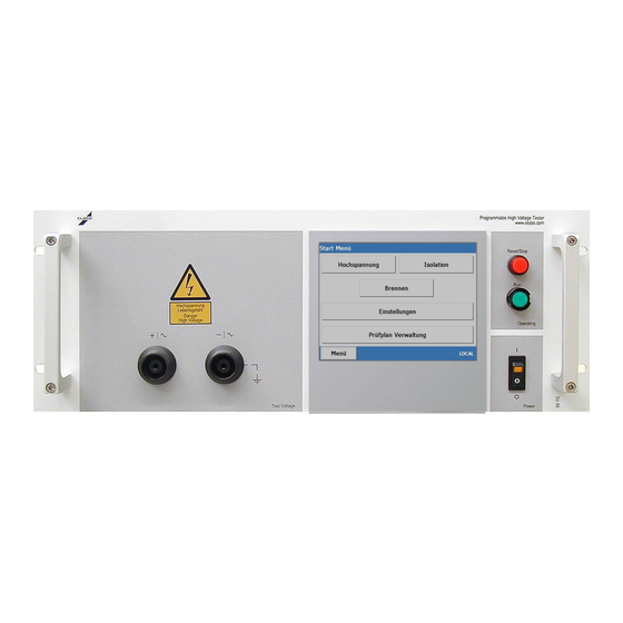
- Page 7 Full-electronic HV-Tester F1-1x 1. INTRODUCTION X9a X7 F1/X1 Note HV-tester with floating output voltage: Connect the " - /~ " pole of the test voltage (hot pole) to the housing (PE) of the test object. This is necessary to get a high- possible measuring accuracy.
- Page 8 Full-electronic HV-Tester F1-1x 1. INTRODUCTION Equipment Function Fuse drawer Adapter for mains fuse S1/H1 Toggle switch/pilot lamp Mains switch with indicator lamp S2/H2 Illuminated button Reset (red) Switching OFF test voltage / Reset Read for testing S3/H3 Illuminated button Set (green) Starting test run (only at display devices) TouchDisplay Operating of the tester...
-
Page 9: Introduction
If repairs are necessary, we will be pleased to provide you with support and supply you with the necessary original spare parts. If you have questions after reading the operating instructions, the ELABO hotline (telephone +49 7951/307-202) is available to provide information. -
Page 10: Abbreviations And Symbols
PC-controlled test station (with control, evaluation, statistics and test plan management via PC software) to a complex fully automatic test station with conveyor belt, autom. contact, labeling etc.. ELABO offers a modern software package for controlling this device series and the management of the data via a PC. Devices with touchscreen display The user can be operated entirely using the touchscreen panel. - Page 11 Full-electronic HV-Tester F1-1x 1. INTRODUCTION The electronic voltage ramp up makes it possible to perform tests on electronic devices that can only be tested non-destructively by slowly in- creasing the test voltage or on test objects with high self-capacitance. Due to the fully electronically regulated test voltage, the variable transformer otherwise used is not necessary.
-
Page 12: Standards Supported
Information technology equipment. Safety • EN 61010-1 Safety regulations for electric measurement, control and laboratory equipment • EN 60601 Medical electrical equipment Name plate ELABO tester The name plate (example) is on the rear of the device. 230 V ; 49 - 61 Hz Nennspg. V 6,3 A Nennstrom A... -
Page 13: Safety Instructions
There is mortal danger when working with high voltage! ELABO has therefore equipped this device and all its components with all the necessary safety features to protect the user against hazards that may occur during correct use. Please note:... -
Page 14: Use As Per Specifications And Exclusion Of Liability
Use as per specifications and exclusion of liability The tester is only allowed to be used for the intended tests. Any other usage is considered incorrect. ELABO is not liable for any resulting damage, the risk is borne solely by the user. Correct usage also includes compliance with the information in these operating instructions. -
Page 15: Protective Facilities / Emergency Off
Full-electronic HV-Tester F1-1x Typs 2. SAFETY REGULATIONS These operating instructions must always be available in the place the device is installed. Incomplete or illegible operating instructions are to be replaced without delay. In this situation we would of course be pleased to be of assistance. -
Page 16: Moisture And Humidity
2.10 Physical/design changes to the system/device Without the prior written approval of ELABO, it is not allowed to make changes, additions or modifications to the system. If this instruction is not followed, the device/machine/system will lose its EC conformity. - Immediately replace parts that are not in correct working condition. -
Page 17: Discharging Test Objects With Internal Capacitance
Full-electronic HV-Tester F1-1x Typs 2. SAFETY REGULATIONS when working with high voltage! Follow DIN EN 50191 (DIN VDE 0104). The EN standard regulates the operation of test systems and test benches. Attention high voltage: The contact elements used for the HV and IS test (test probes etc.) must be designed for the maximum voltage supplied by the device. -
Page 18: Putting Into Operation
Full-electronic HV-Tester F1-1x Typs 3. MAKEREADY PUTTING INTO OPERATION Transport and installation The tester is supplied fully packed and is only allowed to be removed from the packaging in the immediate vicinity of the installation location. The device can be installed in a suitable industrial rack or housing for 19“ plug-ins. The device must be secured against unintentional movement. The surface on which the device is installed must be appropriate for the weight of the tester (approx. 50 kg!) and always provide a secure mount- ing for the device. -
Page 19: Connection To The Connection Box / Connection Panel / Test System
Full-electronic HV-Tester F1-1x Typs 3. MAKEREADY Connection to the connection box / connection panel / test system Mains plug X1 X3/X12 X2/X11 Test object Connection box F1-1x Fig. 3.2: Principle of connection HV Mains plug X1 X3/X12 X2/X11 Test object Connection box F1-1x Fig. -
Page 20: Requirements For Connecting Lines To The Test Object
Full-electronic HV-Tester F1-1x Typs 3. MAKEREADY 3.4.1 Requirements for connecting lines to the test object Under the requirements (current, voltage, mechanical stress, handling, et cetera), must be used appropriate and certificated connecting cables and contacting devices. Use high quality cables: Insulation material with: - a low dielectric con- stant; -low dielectric loss factor; - a high insulation resistance. In addition, an effectual voltage strength, is necessary. -
Page 21: Mains Connection
Full-electronic HV-Tester F1-1x Typs 3. MAKEREADY Mains connection The device is connected to the mains using a mains cable with a plug with an earth contact. Mains connection 230 V/49 - 61 Hz, mains fuse protection 16 A (provided by the customer). Using and controlling Prior to connecting the device to the mains, the following preparations must be made and the following instructions observed. -
Page 22: Connect Usb-Devices
Full-electronic HV-Tester F1-1x Typs 3. MAKEREADY 3.7.1 Connect USB-devices The USB-interface is serving to connect USB-devices - how scanner for barcode reading, USB-memory for import of test-plans respectively for export of measurement data. After connection the tester will accept the USB-device automatically. -
Page 23: Operating Touchscreen Display
Full-electronic HV-Tester F1-1x Typs 3. MAKEREADY Operating touchscreen display Touchscreen displays are touch-sensitive monitors. Areas are defined on them that represent, e. g. buttons (touch-buttons), fields and message windows. There is in principle no difference between the operation of „touch-buttons“ and pressing normal buttons. You operate touch-buttons by touching them with a special „blunt“ stylus or your fingertip. Errors due to triggering actions unintentionally! Always only ever touch one point on the screen. Damage to the surface of the touchscreen display! Do not use any pointed, sharp or hot objects to operate the touch- screen display... -
Page 24: Entering Arbitrary Text
Full-electronic HV-Tester F1-1x Typs 3. MAKEREADY 3.8.2 Entering arbitrary text The screen permits the entry of passwords, test plan names, descriptions, comments, etc. - Touch the field where the entry is to be made (e.g. details, class names, etc). - The screen is displayed automatically if an entry (e.g. password) is ex- pected. Text box (max 256) Deletes the character to the left of the cursor Accepts the entry as the actual value The text entry window is closed. -
Page 25: Password Protection
Protection against unauthorised usage of the device. Prompt after opening „Test with last parameter settings“. It is not possible to make any changes to the parameters for the test object or device. ELABO default setting „MESS“ 3.9.2 Password level 2 Protection against changes to the „test parameters“. Prompt after opening „Test plan management“, „Manuell“ or „Load parameter“. ELABO default setting „PARAM“ 3.9.3 Password level 3 Protection of the „settings“ and Result browser menu. Prompt after open- ing the menu. ELABO default setting „SETUP“ Password level 3 Password level 2 Password level 3 Fig. 3.8: „Start menu“ password levels... - Page 26 Full-electronic HV-Tester F1-1x Typs 3. MAKEREADY Password level 2 Password level 1 Return to the Start menu Fig. 3.9: Password levels „e.g. High voltage test“...
-
Page 27: Switching On
The mains indicator H1 in the Fig. 3.10: ELABO „Start menu“ switch illuminates, the system boots and the display indicates the splash screen for approx. 15 s. Fig. 3.11: ELABO splash screen MyDevice After the boot process, the device indicates the WinCE desktop for a short time (ca. 15 s) Fig. -
Page 28: Changing Language
Full-electronic HV-Tester F1-1x Typs 3. MAKEREADY 3.11 Changing language Language setting for the menu system*). Fig. 3.13: Language setting • Select the „Settings“ menu command (password level 3 necessary). • Set the required language using the „Common - Language“. Accept us- ing Save. The change to the language will only be permanently active after you save the changes, see also chapter 10.9.1 Settings. -
Page 29: State Past Switch On Hv/Is
Full-electronic HV-Tester F1-1x Typs 3. MAKEREADY 3.12 State past switch on HV/IS The device has a mains switch. After the application of the supply voltage, the device is placed in operation by switching on the mains switch. After the mains switch is switched on, the built-in mains indicator H1 illu- minates. The green indicator on the front panel is also briefly illuminated. -
Page 30: Switch On Hv/Is
Full-electronic HV-Tester F1-1x Typs 3. MAKEREADY 3.12.1 Switch on HV/IS The diagram shows the states for the HV/IS test. All prerequisites must be met for the high voltage test (see also state table further forward in this document). The safety circuit(s) must be closed. IN THE „HV ON“... -
Page 31: States Is
Full-electronic HV-Tester F1-1x Typs 3. MAKEREADY The red illuminated pushbutton S2/H2 illuminates and the actual values for output current and output voltage are indicated or can be retrieved via the interface. For information on the selection of the other settings (AC/DC switching, trigger mode, measurement type, voltage setpoint definition, etc.), as well as error messages: see chapter 5 and 10. -
Page 32: Contact Monitoring
Full-electronic HV-Tester F1-1x Typs 3. MAKEREADY 3.13 Contact monitoring On the usage of the device in automatic systems, in many cases it is necessary to check the contact to the test object. One possible method of performing this check can be to monitor the current flowing through the test object with the high voltage applied. For this purpose a base load is connected in parallel with the test object;... -
Page 33: Safety Circuits Sk1 And Sk2
3.14.1 Fault in the device‘s safety circuit Important: If a malfunction is found in the safety circuit incorporated in the device, testing must be interrupted immediately. No further tests are allowed. The device must be sent to ELABO for repair without delay. 3.15 Software-Update Display Important: Software updates are your own risk. -
Page 34: Operating Modes
Full-electronic HV-Tester F1-1x Typs Operating modes OPERATING MODES The device permits basic operating modes: high voltage test or insulation resistance test without ramp and with ramp. The operating modes must be pre-selected in the parameter settings, in the test plan or via the interface. The illustration below gives an overview of the operating modes, voltages and currents. -
Page 35: Overview
Full-electronic HV-Tester F1-1x Typs Operating modes Overview... -
Page 36: Hv/Is-Test
Full-electronic HV-Tester F1-1x Typs Operating modes HV/IS-TEST... - Page 37 Full-electronic HV-Tester F1-1x Typs Operating modes...
- Page 38 Full-electronic HV-Tester F1-1x Typs Operating modes...
- Page 39 Full-electronic HV-Tester F1-1x Typs Operating modes...
-
Page 40: Current Tripping Modes
Full-electronic HV-Tester F1-1x Typs Operating modes Current tripping modes MA_CT_COMPLEX Tripping based on the complex current MA_CT_COMPLEX_DI Tripping based on the complex current and Delta-I MA_CT_REAL Tripping based on the real current MA_CT_REAL_DI Tripping based on the real current and Delta-I MA_CT_PEAK Tripping based on the peak value of the current MA_CT_PEAK_DI Tripping based on the peak value of the current and Delta-I Delta-I trigger current: XXX.X 0-50 mA/ms... -
Page 41: Error Messages
Full-electronic HV-Tester F1-1x Typs 5. ERROR MESSAGES ERROR MESSAGES Depending on the priority of the error, in some circumstances the high voltage is switched off. At the same time the text describing the error is indicated on the display and the related outputs on the interface X7 set (cf. chapter 6). The text describing the error and the errors messages are cleared once the error has been acknowledged using the red illuminated pushbutton (S2/H2), on the digital interface using RESET (X7, pin 3) or using the se- rial command „$SHT“, and the faults have been rectified. -
Page 42: Connections / Interfaces
Full-electronic HV-Tester F1-1x Typs 6. INTERFACES CONNECTIONS / INTERFACES Power connections 6.1.1 High Voltage The high voltage connectors X2 and X3 on the rear and X11 and X12 at the front are used as an output for the test voltage. X11 (+/~) HV socket - connection to object measured X12 (+/~) HV socket - connection to object measured. -
Page 43: X6 Warning Lamp Set 94-2C Connection
Full-electronic HV-Tester F1-1x Typs 6. INTERFACES 6.1.2 X6 Warning lamp set 94-2C connection The round connector is for the connection of the Elabo warning lamp set 94-2C. X6-1 Phase (230 V) for green lamp X6-2 Phase (230 V) for red lamp... -
Page 44: Interfaces
X9 also as USB-INTERFACE or Ethernet-INTERFACE possible. For device support: Driver-software and driver-manuals are located at the ELABO Support CD, enclosed to the device manual. 6.2.2 USB-Interface X8/ Ethernet-Interface X9a X8 USB-interface for software-update at tester with touch display - see chapter. -
Page 45: Digital Interface X7
Full-electronic HV-Tester F1-1x Typs 6. INTERFACES 6.2.3 Digital interface X7 For the connection of the safety circuits and for external control, the device has a 25-pin connector X7. Fig. 6.3: View of connector X7 Note: The inputs and outputs described in the following are connected to X7 in the standard device. Additional digital outputs can be purchased as an option. - Page 46 Full-electronic HV-Tester F1-1x Typs 6. INTERFACES Overcurrent trip „I > Imax“: „Positive switching“ transistor output. In case of an overcurrent trip, the output is set to „High“. Pin 8 I>Imax Load rating: 24 V/max. 50 mA High voltage applied „HV-On“: „Positive switching“ transistor output. The output is set to „High“ if the high- voltage is switched ON. Pin 9 HV-On Load rating: 24 V/max. 50 mA Test „Accept“...
-
Page 47: Inputs
Full-electronic HV-Tester F1-1x Typs 6. INTERFACES 6.2.3.2 Inputs A „High“ signal on a digital input on the digital interface can be achieved in two different ways. • Connect the auxiliary voltage +Ue (X7, Pin22) to the related input. • Apply an external auxiliary voltage of +24 V DC to the related in- put pin. However, in this case the ground for this supply voltage is to be connected to GND (X7, pin 17). An open (digital-) input is recognized as LOW. Note delay-time: Between the reset-operation of an input and a follow- ing set operation of an other input, a minimum delay-time of 100 ms must exist (reaction time of the electronic, relay setting, ...). -
Page 48: Additional Digital Interface Opt1-6 (Option)
Full-electronic HV-Tester F1-1x Typs 6. INTERFACES Pins not connected Pin 1, pin 5; pin 6, pin 7, pin 14, 6.2.3.3 Additional digital interface OPT1-6 (option) See also chapter 12.5 "Output step" and Chapt. 14 „Options for the device“. Expanded digital interface option F1-1x E06 These 6 additional digital outputs can be switched on/off in the test plan. For this purpose the „Output“ function is to be inserted at a suitable point in the test plan and the related output and its state (on/off) defined. A further possibility is activation / deactivation via serial remote control (see remote... -
Page 49: Accessories And Attachments
(magnetic switch). The second start must come from the computer via the PC interface (HV is applied - see also chapter 3.12). Suitable test cabinets from ELABO: 94-3A series - manual protective hood 94-3B series - automatic protective hood (pulse) -
Page 50: Warning Lamp Set 94-2C
Full-electronic HV-Tester F1-1x Typs 7. ACCESSORIES (Option) Warning lamp set 94-2C In the case of test voltages over 1000 V the HV device must be equipped with a warning lamp set (red and green lamps). See DIN VDE 0104. Fig. 7.2: Warning lamp set 94-2C Before connecting the warning lamps the tester has to be discon- nected from the power supply (Pull out plug!) ! The warning lamps are connected to the rear of the tester via the socket... -
Page 51: Maintenance And Care
If a fuse should blow, it is only allowed to be replaced once, if the fuse blows again after its replacement, please send the device to your nearest ELABO service centre of contact the ELABO hotline (+49 7951 307-202). Only use the type of fuse stated! Work inside the device only may be executed by an electric quali- fied employee. -
Page 52: Technical Data
Full-electronic HV-Tester F1-1x Typs 9. SPECIFICATION TECHNICAL DATA Device-specific technical data Device F1-1A/F1-1M F1-1A Z200 F1-1B/F1-1N F1-1C/F1-1P F1-1D/F1-1Q F1-1M Z200 High voltage Output voltage float- ing/synchronous with 0,1 ... 2,5 kV 0,1 ... 1,5 kV 0,2 ... 3,5 kV 0,3 ... 5,0 kV 0,4 ... -
Page 53: Common Technical Data F7-1X
Full-electronic HV-Tester F1-1x Typs 9. SPECIFICATION Common technical data F7-1X Mains connection: 230 V +10% -10% / 49 - 51 Hz Operating temperature: C - 50 Atmospheric humidity: 25 - 75% rel. humidity Dimensions: 19“, depth 360 mm 9.2.1 HV TEST Resolutions/measuring errors Current tripped based on either: Real current, complex current (effective),... -
Page 54: Insulation Resistance Measurement With Hv-Dc
Full-electronic HV-Tester F1-1x Typs 9. SPECIFICATION Options See chapter 13. 9.2.2 Insulation resistance measurement with HV-DC Measurement ranges: 1 MOhm, 10 MOhm, 100 MOhm Contact monitoring Rmax: Dependent on the measurement range Ramp function: Ramp up/ramp down Resolutions/measuring errors Resolution of resistance indication: kOhm ( 1 MOhm range) 100 kOhm ( 10 MOhm range) MOhm (100 MOhm range) -
Page 55: Interfaces, Miscellaneous
Full-electronic HV-Tester F1-1x Typs 9. SPECIFICATION Interfaces, miscellaneous Internal program memory (touchscreen display): >150 parameter sets Safety circuit: SK 1 and SK 2 Interfaces: digital (Standard) 6 additional digital outputs OPT 1-6 (option) RS232 (Standard) and Ethernet (Option) or USB (Option) Tester with current limitation ( 3 MA AC/5 MA DC) current limitation", see chap. -
Page 56: Touchscreen Display Menu System
Full-electronic HV-Tester F1-1x Typs 10. Menu System TOUCHSCREEN DISPLAY MENU SYSTEM The device is operated and the device parameters and text parameters are set using the touchscreen display. 10.1 General The menu system is provided by a dedicated computer with Windows CE as the operating system. The Windows CE computer passes the com- mands and parameters to the controller for the device hardware that then undertakes the tests. -
Page 57: Overview, Hv Test Example
Full-electronic HV-Tester F1-1x Typs 10. Menu System 10.1.1 Overview, HV test example Selected test step Continuous test or test Manual ramp up time active Manual HV setting Continuous test max. 999.9s Actual test time... -
Page 58: Main Start Menu
Full-electronic HV-Tester F1-1x Typs 10. Menu System 10.2 Main start menu The selection of operating modes may vary depending on the options fitted to the device. Option Result-Browser Fig. 10.2: Start menu The selection of the function for high voltage / insulation / protective earth conductor / function (option) is the same. -
Page 59: Manual Test
Full-electronic HV-Tester F1-1x Typs 10. Menu System 10.3 Manual test After opening the manual test, the operator must enter the password for level 2 (parameters). The parameter screen for the test type selected (HV; IS; PE; FK) is dis- played. In the example the parameter screen for the HV test has been selected. - Page 60 Full-electronic HV-Tester F1-1x Typs 10. Menu System Buttons for setting the test voltage in the „manual“ Test parameters ramp mode Accept Fig. 10.5: Manual test - ready for test screen The device now waits for the manual confirmation of the start. This con- firmation can be given using the green RUN button on the device or by closing the protective hood on the test cabinet. In the case of operation via the front panel (local) the green RUN button (S3/H3) on the device must be pressed twice (2nd start), on this topic also see chapter 3.12.1.
- Page 61 Full-electronic HV-Tester F1-1x Typs 10. Menu System After the end of the test time or manual interruption (red reset S2/H2) the device indicates the result of the test. Accept Fig. 10.7: Manual test - test screen - acceptable test result If the device detects faults, the test is interrupted immediately and a cor- responding error message displayed in plain text. The erroneous test must be acknowledged using the red reset button S2/H2.
-
Page 62: Testing With Last Parameter Settings
Full-electronic HV-Tester F1-1x Typs 10. Menu System 10.4 Testing with last parameter settings The device loads the settings saved last and starts the test. As it is not possible to change the test parameters, it is only necessary to enter the password for level 1 (measurement). -
Page 63: Load Parameter
Full-electronic HV-Tester F1-1x Typs 10. Menu System 10.5 Load parameter After opening „Load parameter“, the operator must enter the password for level 2 (parameters). The menu is used for adding test steps. Test steps can be assembled into test plans and in this way produce a defined test sequence (test plan management). The related test steps must be defined for the individual test types (HV, IS; PE; FK). The existing test steps are listed in the field "Step" (for example HV-Steps). Test step - indicates the names of the test steps defined for the type (in this case HV-step). - Page 64 Full-electronic HV-Tester F1-1x Typs 10. Menu System Fig. 10.12: Load parameter - test steps - parameter screen - Change the required parameters the screen/s. The test parameters for the test types are described in chapter 11 „Menu“ - closes the parameter screen and returns to the start menu. „Save“ - saves the changes made. You can assign a new name to the modified step or use the old name (overwrite the parameters) .
-
Page 65: Test Plan Management And Automatic Testing
Full-electronic HV-Tester F1-1x Typs 10. Menu System 10.6 Test plan management and automatic testing After opening „Test plan management“, the operator must enter the pass- word for level 2 (parameters). The menu is used for adding test plans. Test plans contain one or more test steps and so form a defined test sequence. The sequence is displayed in the form of a list; the device runs through the list from top to bottom. Depending on the options fitted to the device, e.g. HV, IS, Burn steps that are used to provide information to/prompt the operator, to poll buttons or to poll/set a digital input/output. -
Page 66: Import/Export Of Test Plans
Full-electronic HV-Tester F1-1x Typs 10. Menu System „Copy“ - creates a copy of the test plan marked. The device prompts for the new test plan name. Then the test plan screen appears, see chapter 10.7. „Test plan management“. „Remove“ - deletes the test plan marked from the list (after prompt). At- tention - a deleted test plan cannot be restored. -
Page 67: Editing/Adding Test Plans
Full-electronic HV-Tester F1-1x Typs 10. Menu System 10.7 Editing/adding test plans Select the required test plan on the list. The box on the right indicates information on the test plan. Fig. 10.15: Test plan management - test plan selection Test types Burn General test steps Fig. 10.16: Test plan management - editing test plan The screen is divided into three columns. - Page 68 Full-electronic HV-Tester F1-1x Typs 10. Menu System Available steps - this column indicates the existing test steps for the function (test type) selected. General test steps do not generally have test steps. „Test steps“ - this column displays the test steps and sequence in the test plan. Fig. 10.17: Test plan management - assembling test plan Assemble test plans as follows ...
- Page 69 Full-electronic HV-Tester F1-1x Typs 10. Menu System Fig. 10.17: Test plan management - Save modified test step No: Saves the modified test step with the same name (Attention: The source test step, also). Yes: Enter a new name for the step. This "special" test step exists only in this test plan.
-
Page 70: Automatic Testing - Selecting Test Plans
Full-electronic HV-Tester F1-1x Typs 10. Menu System 10.8 Automatic testing - selecting test plans Select the required test plan on the list. The box on the right indicates information on the test plan. „Load“ opens the selected test plan so it can be run. Fig. 10.18: Test plan management - loading test plan With test running: universal test steps Actual measured values and values de- Test steps fined for the active test step. -
Page 71: Serial No. Automatic
Full-electronic HV-Tester F1-1x Typs 10. Menu System With test running: universal test steps Actual measured values and values de- Test steps fined for the active test step. universal test steps C o n t i n u o u s Status of the test- ACCEPT/FAULT steps... -
Page 72: Settings (Device Parameters)
Tabs Fig. 10.20: Setting device parameters Note "protected menu": In the menu tab "setting/Elabo" includes a sepa- rate protected menu part. This part contains several basic settings, special of this device variant. This settings are predefined by ELABO. Normally, the user has to do no changes of this settings. The protected part is visible only, if entering a non-public pass word. - Page 73 The selection of the data sets and the print-out, is carry out in the result browser. Pass word - is pre-defined by ELABO. If the password is erased or not correct, the printout will run in "evaluation mode" of the printer software. Contact the ELABO service to get a new pass word...
-
Page 74: Communication
Full-electronic HV-Tester F1-1x Typs 10. Menu System 10.9.2 Communication For remote control using PC and communication with an ELABO function test plug-in or special device. A combination of max. 2 interfaces is pos- sible. E.g. RS232/Ethernet; USB/Ethernet. Fig. 10.22: Setting device parameters - Communication RS232 Serial interface in the device for remote control. COM1 / COM2 possible depending on the combination. -
Page 75: Device
Off - operation without test cabinet and with all other ELABO test cabinets. On - for ELABO 93-4B series test cabinet. The device outputs a pulse to the test cabinet and as a result opens the lock. The pulse is gener- ated at the end of the test time or after a „reset“. Is necessary if the... - Page 76 Full-electronic HV-Tester F1-1x Typs 10. Menu System Save results (Result browser) Off - The result storage is not active. The measurement data are not visible in the result browser. On - The test results are recorded and visible under the serial number in the result browser.
-
Page 77: Elabo
Full-electronic HV-Tester F1-1x Typs 10. Menu System 10.9.4 ELABO Indicates the device number, the software version and possible the hard- ware options fitted to the device. Fig. 10.25: Setting device parameters - Elabo device configuration... -
Page 78: Passwords
- passwords are active. For starting a new function, it is neces- sary to enter the password. Note - Pass words lost: Request the ELABO service for a "master pass- word". By using the master password it is possible to unlock the device. -
Page 79: Special
If the fault occurs again, a fault in the monitoring is to be as- sumed. For safety reasons the device must be sent to the manufacturer for checking. „Reset safety current limitation“ is protected using a special password. The password can be requested from ELABO. -
Page 80: Time/Date
Full-electronic HV-Tester F1-1x Typs 10. Menu System 10.9.7 Time/Date Use the „Time/Date“ tab to enter a new date or time. Setup the CE-system with the new date/time by touching the time-set button. Time/Date System date/-time Input fields for date and time Fig. 10.28: Setting device parameters - Date/Time... -
Page 81: Test Parameters
Full-electronic HV-Tester F1-1x Typs 11. Test parameter TEST PARAMETERS 11.1 Setting parameters high voltage test On this menu the settings for the HV tests are made. Depending on which device variant you have, some of the parameters given in the following may not be available or it may not be possible edit some parameters. - Page 82 Full-electronic HV-Tester F1-1x Typs 11. Test parameter The test voltage is then increased linearly from the start voltage to the test voltage in one time unit. on - voltage range from 100 V AC/ from 200V DC (option) off - no ramp function, the full test voltage is applied. Test voltage Start voltage t (s)
-
Page 83: Ramp Function
Full-electronic HV-Tester F1-1x Typs 11. Test parameter 11.1.2 Ramp function Fig. 11.2: HV test parameters - Ramp function Manual voltage adjustment on/off“ - switches on/off the ramp function for the test voltage. off - no manually test voltage setup. on - the test voltage can be set manually. Two buttons are displayed on the test screen for this purpose. -
Page 84: Test Time
Full-electronic HV-Tester F1-1x Typs 11. Test parameter On - voltage ramp down active. The test voltage is reduced linearly from the test voltage to the start voltage as per the ramp down speed and then switched off. Ramp down speed (V/s) - the test voltage is reduced linearly by the value given per time unit. -
Page 85: Tripping Current
Full-electronic HV-Tester F1-1x Typs 11. Test parameter 11.1.4 Tripping current Fig. 11.5: HV test parameters - Tripping current Tripping type - enter the current of portion of the current that is to be used for tripping. Active - evaluation of the real part of the test current (effective) Apparent - evaluation of the complex current (test current with real and reactive portion), Peak - evaluation based on the peak value of the test current. - Page 86 Full-electronic HV-Tester F1-1x Typs 11. Test parameter Max current rise delta I (A/ms): - enter the max. rate of change of cur- rent allowed. The limit is: 0-50 mA/ms range 1 mA 0-500 mA/ms range 10 mA 0-5000 mA/ms range =>100 mA Contact monitoring „on/off“ - switches on the evaluation for the minimum current. During the test a pre-defined minimum current must flow. This ensures contact is made to the test object. off - no evaluation of the minimum current.
-
Page 87: Setting Parameters Insulation Resistance Test Is
Full-electronic HV-Tester F1-1x Typs 11. Test parameter 11.2 Setting parameters insulation resistance test IS insulation resistance test are made. The On this menu the settings for the options F1-1x E01 (DC) and E02 (ISO) are required for the IS test IS tests are made using DC, with the test object isolated from the mains. The insulation resistance between live parts and the housing is measured and evaluated. - Page 88 Full-electronic HV-Tester F1-1x Typs 11. Test parameter Start voltage „on/off“ - defines whether the test voltage is switched on at the lowest possible voltage or from a higher pre-defined voltage. on - voltage range from 100 V AC / from 200 V DC (option) off - no ramp function, the full test voltage is applied. Test voltage Start voltage t (s) Start voltage (V) - defines the voltage value from which the high voltage ramp starts.
-
Page 89: Ramp Function
Full-electronic HV-Tester F1-1x Typs 11. Test parameter 11.2.2 Ramp function Fig. 11.7: ISO test parameters - Ramp function Manual voltage adjustment on/off“ - switches on/off the ramp function for the test voltage (see also HV-ramp function). off - no manually test voltage setup. on - the test voltage can be set manually. Two buttons are displayed on the test screen for this purpose. -
Page 90: Test Time
Full-electronic HV-Tester F1-1x Typs 11. Test parameter 11.2.3 Test time Fig. 11.8: ISO test parameters - Test time Continuity test „on/off“ - switches between continuous test and testing with test time. A I>Imax fault (flashover) will end the test. off - test time active. The test voltage is applied for the duration of the test time. on - continuous test active. The test voltage is applied continuously. The test must be interrupted manually using the red „Reset“ button. -
Page 91: Range
Full-electronic HV-Tester F1-1x Typs 11. Test parameter 11.2.4 Range Fig. 11.9: ISO test parameters - Range Range (MOhm)- select the measurement range in which the insulation resistance is to be evaluated. The range is dependent on the expected resistance. 1 MOhm measurement range 10 MOhm measurement range 100 MOhm measurement range Rmin (MOhm): - lowest insulation resistance allowed. - Page 92 Full-electronic HV-Tester F1-1x Typs 11. Test parameter parameter is used for the contact monitoring. The Rmax is dependent on the measurement range and can be between 1 and 100 MOhm.
-
Page 93: Setting Parameters Burn (Option)
Full-electronic HV-Tester F1-1x Typs 11. Test parameter 11.3 Setting parameters BURN (Option) BURN with AC voltage, for the localisation of low insulation points inside the test object. By the over-flash of the voltage, it is possible, to welding out the insulation fault. The maximum short-circuit current at BURN is: appr. 250 mA in 2,5 kV range and appr. 150 mA in 5 kV range. The BURN mode, don't ensures a non destructive testing, since the tripping current release is blocked. -
Page 94: Ramp Function
Full-electronic HV-Tester F1-1x Typs 11. Test parameter 11.3.2 Ramp function Fig. 11.11: BURN test parameters - Ramp Ramp up „Manually/on/off“ - switches off the ramp function for the BURN function off - no ramp function, the full burn voltage is applied. Manually - the burn voltage can be set manually. -
Page 95: Test Time
Full-electronic HV-Tester F1-1x Typs 11. Test parameter 11.3.3 Test time Fig. 11.13:BURN parameters - Test time Continuous test „on/off“ - switches between continuous burning and burning with test time. off - test time active. The burning voltage is applied for the duration of the test time. -
Page 96: Setting Parameters Function Test (Fk)
Full-electronic HV-Tester F1-1x Typs 11. Test parameter 11.4 Setting parameters function test (FK) function test are made. The option On this menu the settings for the F9-7M E20 (function test) is required for the function test Function tests are undertaken at function voltage, this can be a voltage from an internal or external voltage source or also at mains voltage. During the function test, current, voltage and power are measured and evaluated. -
Page 97: Ramp / Time
Full-electronic HV-Tester F1-1x Typs 11. Test parameter 11.4.2 Ramp / time Fig. 11.15: Function test parameters - Ramp/time Test object supply at ramp up „on/off“ - switches on/off the ramp func- tion for the function test voltage. off - no ramp function. The test voltage is set by the source and then applied. -
Page 98: Tripping
Full-electronic HV-Tester F1-1x Typs 11. Test parameter Test time (s) - the test time can be set from 000.1 to 999.9s. The test time is irrelevant in the case of „Continuous test on“. Death time „on/off“ - defines a period before the actual measurement. The function voltage is applied, the monitoring of current and power is, however, deactivated for the time entered. -
Page 99: Universal Test Steps
Full-electronic HV-Tester F1-1x Typs 12. UNIVERSAL TEST STEPS UNIVERSAL TEST STEPS Info, Question, Pause, Output are universal test steps. This test steps are not for "Manual Testing" available. Universal test steps are only in automatic test sequences (test plans) usable. The creation of universal steps is only in the menu "Edit test plan" possible. -
Page 100: Info Step
Full-electronic HV-Tester F1-1x Typs 12. UNIVERSAL TEST STEPS - Type the name/text, by touch the letter on the screen, max 50 character. . - Accept the final text with "Enter". - Enter the Info text now. - The question text is query. - Type the text for the user information (see above). - Accept the final text with "Save". Fig. 12.3: Information text Note: Create Question, Info, Pause steps in the same way. 12.2 Info step The info step can be inserted in any place in the test plan. Info steps are for the information/warning of the operator by showing an info text . The Info text box is showing in the test sequence. Quit the information by touching the "OK"... -
Page 101: Question Step
Full-electronic HV-Tester F1-1x Typs 12. UNIVERSAL TEST STEPS 12.3 Question step The question step can be inserted in any place in the test plan. Question steps are asking the operator about information of the test object (e.g. damages on the item, etc.). The question text box is showing in the test sequence. Answer the question by touching the "Yes" or "no" button. Crea- tion of Question steps, see Chapt. 12.1 - above. A n s w e r w i t h "Yes / No"... -
Page 102: Output Step (Option)
Full-electronic HV-Tester F1-1x Typs 12. UNIVERSAL TEST STEPS 12.5 Output step (Option) See also Chapt. 6.2.3.3 "Digital outputs OPT1 - 6". The output step is only visible, if the option OPT ( digital outputs E06) is integrated in the tester and also activated. Option E06 enhanced the tester with 6 additional outputs. -
Page 103: Result Browser (Option)
Full-electronic HV-Tester F1-1x Typs 13. RESULT BROWSER RESULT BROWSER (OPTION) Via this menu item a measurement browser is called. With this program the indication is possible, of the measurements of a single test item, a group of test items (list), test items of a type (barcode) or all available test items. - Page 104 Full-electronic HV-Tester F1-1x Typs 13. RESULT BROWSER þ Filter active "Time period" Listing Good test items þ shows only good test items on the list. Listing Fault test items þ shows only test items with test result „Fault“ in the list. Updating list - updates the display list, e.g. is required after the change Updating list of a filter criterion.
-
Page 105: Display List
Full-electronic HV-Tester F1-1x Typs 13. RESULT BROWSER 13.2 Display list The number of shown items is dependent on the selected filter criterion, see chapt. 13.1. Fig. 13.4: Result browser - display list (example) Green dot - Result of the test „Good“ All measured values lay within the tolerances provided in the test plan. Red dot - Result of the test “Fault”. One of the measured values lay out- side the tolerances provided in the test plan. Barcode – (Serial number )- of the test item. If a barcode/serial number is listed repeatedly, the test item was appropriately often tested with this barcode. -
Page 106: Showing/Printing Measurements
Full-electronic HV-Tester F1-1x Typs 13. RESULT BROWSER 13.3 Showing/printing measurements The number of shown test items is dependent on the selected filter crite- rion, see Chapt. 13.3. Test results - has an effect on “page view" measurements, see Fig. 13.6" . Page view with measurements of the selected test item. þ Test plan - has an effect on “ “page view", see Fig. 13.6". þ Page view with test plan of the selected test item. Page view - shows measurements of the selected test item in form of a page view paper list. - Page 107 Full-electronic HV-Tester F1-1x Typs 13. RESULT BROWSER Fig. 13.6: Result Browser - measurement data Print - out the measurement data to a connected printer . The printer must Print be enabled in the menu "setup/common". Close - closing the measurement data. Close Save - saves the measurement data to a USB-memory stick as text file.
-
Page 108: Options And Add-Ons For The Devices
Full-electronic HV-Tester F1-1x Typs 14. OPTIONS/ADD-ONS OPTIONS AND ADD-ONS FOR THE DEVICES The options discribed in follow, are special accomplishments or exten- sions of the standard device. This options must be ordered at factory or the device has to be upgraded also in the factory. A self-upgrad is not permissible by safety reasons. -
Page 109: Safety Current Limitation Option E03
Full-electronic HV-Tester F1-1x Typs 14. OPTIONS/ADD-ONS 14.1 Safety current limitation Option E03 Option “Safety current limitation” is restricting the output current of the HV-tester to 3 mA for AC respectively 5 mA for DC and is switching OFF the high voltage at an over run of the current limitation. The current limitation is caring out by a passive circuit (AC+DC) and active circuit. -
Page 110: Load Characteristic Current-Limited
Full-electronic HV-Tester F1-1x Typs 14. OPTIONS/ADD-ONS 14.1.1 Load characteristic current-limited AC-Load characteristic - / DC-Load characteristic at rated operation test current low range AC isolated from earth AC earthbound 4,0 kV test voltage test current high range AC isolated from earth AC earthbound 8,0 kV test voltage... - Page 111 Full-electronic HV-Tester F1-1x Typs 14. OPTIONS/ADD-ONS 14.1.1 Special notes Safety current limit E03 The tester is equipped with a safety current limitation by an active-redun- dant system (additional hardware component for 3 mA for AC currents) and a passive resistor (12 mAeff maximum) connected in series with the output sockets of the test voltage. Additional the measurement values are recorded cyclically by a micro controller. If the limit value is exceeded, the test is automatically switched off.
-
Page 112: Voltage Readback Unit E04
Full-electronic HV-Tester F1-1x Typs 14. OPTIONS/ADD-ONS 14.2 Voltage Readback unit The readback unit option E04 serves for controlling if the high voltage is supplying the test item. By this it is guaranteed that the test item is safely bonded and supplied to the correct voltage. In addition to the two HV-energy lines, two sense lines have to be connected to the connecting terminals (four wire measuring). - Page 113 Full-electronic HV-Tester F1-1x Typs 14. OPTIONS/ADD-ONS...
- Page 114 DIN EN 60204-1; VDE 0113-1 DIN EN 13849-1 DIN EN 50191; VDE 0104 (Normen in den jeweils aktuellen Ausführungen) (All standards in actual version) Dokumentations-Beauftragter : Mr. Andreas Bausch, ELABO GmbH Authorized person for documentation: Thomas Hösle Geschäftsleitung/Management Name/Name Funktion/Function 24.05.2016...
- Page 115 ELABO GmbH Rossfelder Strasse 56 74564 Crailsheim Germany Fon + 49 7951 307-0 Copyright - ELABO GmbH Fax + 49 7951 307-66 This print is only destined for the recipient of the unit and has to be used info@elabo.de for the intended purpose only.
Need help?
Do you have a question about the F1-1 Series and is the answer not in the manual?
Questions and answers