Table of Contents
Advertisement
Quick Links
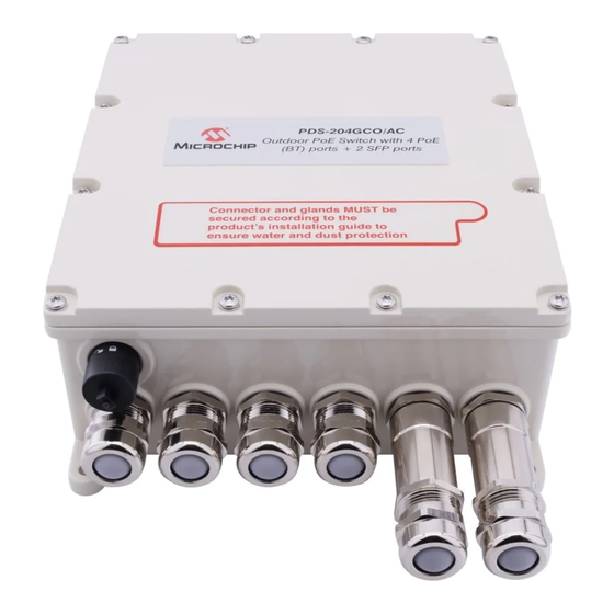
Outdoor 4 Port BT PoE Switch + 2 SFP Uplink Port
Introduction
™
Microchip's PDS-204GCO
for four powered devices and connect them to the network through data uplink ports. The PDS-204GCO switch can
be remotely managed through the web or SNMP, allowing monitoring and control of the device and its ports. The
PDS-204GCO switch supports 10/100/1000 Mbps data rates on the RJ45 Gigabit ports and 100/1000/2500 Mbps on
the SFP ports. It is powered through wide-range AC input (100 V
rated and has an extended temperature range. Therefore, it can be installed in an outdoor environment.
In a typical installation, the PDS-204GCO switch provides power to four outdoor devices, such as WLAN AP, WLAN
Mesh, IP Camera, and so on.
Audience
This guide is designed for personnel who install and maintain the switch. These persons must be familiar with
electronic circuitry and wiring practices, and qualified and experienced electronic or electromechanical technicians.
©
2022 Microchip Technology Inc.
and its subsidiaries
Hardware Installation Guide
switch is a 4 + 2 ports outdoor PoE switch. It can provide power and data connectivity
PDS-204GCO/AC
–240 V
). The PDS-204GCO switch is IP66/IP67
AC
AC
User Guide
™
DS00004837A-page 1
Advertisement
Table of Contents

Related Manuals for Microchip Technology PDS-204GCO/AC


Summary of Contents for Microchip Technology PDS-204GCO/AC
-
Page 1: Introduction
This guide is designed for personnel who install and maintain the switch. These persons must be familiar with electronic circuitry and wiring practices, and qualified and experienced electronic or electromechanical technicians. User Guide DS00004837A-page 1 © 2022 Microchip Technology Inc. and its subsidiaries... -
Page 2: Table Of Contents
The Microchip Website..........................21 Product Change Notification Service....................21 Customer Support..........................21 Microchip Devices Code Protection Feature..................21 Legal Notice............................21 Trademarks............................22 Quality Management System........................ 23 Worldwide Sales and Service........................24 User Guide DS00004837A-page 2 © 2022 Microchip Technology Inc. and its subsidiaries... -
Page 3: Hardware Description
Four Copper cable glands • Two fiber cable glands + cable gland extender • Six ports cable gland caps • Mechanical mounting kit—enables pole mounting (including with unit) User Guide DS00004837A-page 3 © 2022 Microchip Technology Inc. and its subsidiaries... -
Page 4: Mechanical View
™ PDS-204GCO/AC Mechanical View Mechanical View The following figures show the mechanical view of the PDS-204GCO switch. Figure 2-1. Mechanical View User Guide DS00004837A-page 4 © 2022 Microchip Technology Inc. and its subsidiaries... -
Page 5: Installation
The PDS-204GCO unit can be mounted on a wall/bench (all kinds of flat surfaces: wood, brick, concrete, and so on) using the mounting holes. Fasten the PDS-204GCO using four screws, as shown in the following figure. Figure 3-1. Wall Mounting 172mm (6.772in) 172mm (6.772in) User Guide DS00004837A-page 5 © 2022 Microchip Technology Inc. and its subsidiaries... -
Page 6: Pole Mounting Installation
The unit must be installed with DATA IN, and DATA & PWR OUT ports facing down, as shown in the following figures. Dimensions of support Pole diameter: 60 mm to 200 mm (2.5 inches to 8 inches) Table 3-2. Installation of Units on Pole User Guide DS00004837A-page 6 © 2022 Microchip Technology Inc. and its subsidiaries... -
Page 7: Connecting Network Cables
Insert the cable through metal gland, rubber seal, and pressure fingers and plug into the port number 1. Secure all glands till the rubber gasket is tightly closed around the cable. User Guide DS00004837A-page 7 © 2022 Microchip Technology Inc. and its subsidiaries... - Page 8 • Secure the gland until the rubber gasket is firmly closed around the cable. • The PDS-204GCO switch is not shipped with Ethernet cable and RJ45 male connectors. User Guide DS00004837A-page 8 © 2022 Microchip Technology Inc. and its subsidiaries...
-
Page 9: Connecting Fiber Optic Cable
™ PDS-204GCO/AC Connecting Network Cables Connecting Fiber Optic Cable Figure 4-1. Connecting Fiber Optic Cable SFP Module Optical fibre cables User Guide DS00004837A-page 9 © 2022 Microchip Technology Inc. and its subsidiaries... - Page 10 Insert the cable through metal gland, rubber seal, and pressure fingers and plug into the Uplink port. Secure the gland until the rubber gasket is firmly closed around the cable. Note: SFP cord must be outdoor use grade. User Guide DS00004837A-page 10 © 2022 Microchip Technology Inc. and its subsidiaries...
-
Page 11: Connecting Power Cable
Diameter: 3/16 in.–3/8 in. Diameter: 5.0 mm–9.5 mm Approved for indoor and outdoor applications. The following figures show how to connect the power connector. Figure 5-1. Connecting AC Connector User Guide DS00004837A-page 11 © 2022 Microchip Technology Inc. and its subsidiaries... - Page 12 33mm (1 5/16 in) 33mm (1 5/16 in) 8mm (5 /16 in) 8mm (5 /16 in) 0.5 Nm 0.5 Nm 25mm (1 in) 25mm (1 in) 1.5 Nm 1.5 Nm User Guide DS00004837A-page 12 © 2022 Microchip Technology Inc. and its subsidiaries...
-
Page 13: Appendix A: Safety And Warnings
être utilisées comme prises de service téléphonique traditionnel. Connecter seulement des connecteurs de données RJ45 à ces prises. Le câblage Ethernet connexe doit être limité à l'intérieur de l'immeuble. • Pour disposer/jeter ce produit, suivre les lois et règlementslocaux. User Guide DS00004837A-page 13 © 2022 Microchip Technology Inc. and its subsidiaries... -
Page 14: Appendix B: Troubleshooting
Ethernet source to the remote terminal. 5. Try to reconnect the same PD to a different PoE switch. If it works, then there is probably a faulty port or faulty RJ45 connection. User Guide DS00004837A-page 14 © 2022 Microchip Technology Inc. and its subsidiaries... -
Page 15: Appendix C: Specifications
• 1000BASE-X • 2500BASE-X • 100BASE-FX Output (DATA PWR OUT) RJ45 female socket, with DC voltage AC Power IN 3 Pins AC power in—Line, Neutral, and Earth Ground. User Guide DS00004837A-page 15 © 2022 Microchip Technology Inc. and its subsidiaries... -
Page 16: Appendix D: Standards
• IEEE 802.3bt (PoE) standards • RoHS compliant • WEEE compliant • REACH compliant • Dust and water intrusion – IEC60529, level IP66/IP67 – NEMA 250, level 4x User Guide DS00004837A-page 16 © 2022 Microchip Technology Inc. and its subsidiaries... -
Page 17: Appendix E: Recycling And Disposal
• If you purchase a replacement product, hand your complete old product back to the retailer. He must accept it, as required by the national WEEE legislation. User Guide DS00004837A-page 17 © 2022 Microchip Technology Inc. and its subsidiaries... -
Page 18: Ordering Information
Ordering Information Ordering Information Table 11-1. Ordering Information Item Description Product Name Microchip Outdoor PoE Switch Part Number PDS-204GCO/AC Description 4 PoE ports + 2 SFP uplink port User Guide DS00004837A-page 18 © 2022 Microchip Technology Inc. and its subsidiaries... -
Page 19: References
• Microchip Getting Started With PDS204GCO Switch Configuration User Guide ™ • Microchip PDS-204GCO Web Management User Guide ™ • Microchip PDS-204GCO Command Line Interface (CLI) User Guide User Guide DS00004837A-page 19 © 2022 Microchip Technology Inc. and its subsidiaries... -
Page 20: Revision History
The revision history describes the changes that were implemented in the document. The changes are listed by revision, starting with the most current publication. Revision Date Description 12/2022 Initial Revision User Guide DS00004837A-page 20 © 2022 Microchip Technology Inc. and its subsidiaries... -
Page 21: Microchip Information
Microchip products with your application. Use of this information in any other manner violates these terms. Information regarding device applications is provided only for your convenience and may be superseded User Guide DS00004837A-page 21 © 2022 Microchip Technology Inc. and its subsidiaries... -
Page 22: Trademarks
The Adaptec logo, Frequency on Demand, Silicon Storage Technology, and Symmcom are registered trademarks of Microchip Technology Inc. in other countries. GestIC is a registered trademark of Microchip Technology Germany II GmbH & Co. KG, a subsidiary of Microchip Technology Inc., in other countries. -
Page 23: Quality Management System
™ PDS-204GCO/AC Quality Management System For information regarding Microchip’s Quality Management Systems, please visit www.microchip.com/quality. User Guide DS00004837A-page 23 © 2022 Microchip Technology Inc. and its subsidiaries... -
Page 24: Worldwide Sales And Service
Tel: 631-435-6000 Sweden - Stockholm San Jose, CA Tel: 46-8-5090-4654 Tel: 408-735-9110 UK - Wokingham Tel: 408-436-4270 Tel: 44-118-921-5800 Canada - Toronto Fax: 44-118-921-5820 Tel: 905-695-1980 Fax: 905-695-2078 User Guide DS00004837A-page 24 © 2022 Microchip Technology Inc. and its subsidiaries...
Need help?
Do you have a question about the PDS-204GCO/AC and is the answer not in the manual?
Questions and answers