Table of Contents
Advertisement
Available languages
Available languages
Quick Links
Advertisement
Chapters
Table of Contents

Subscribe to Our Youtube Channel
Related Manuals for Cosmo C2PGUWMZ


Summary of Contents for Cosmo C2PGUWMZ
- Page 1 G U T E S K L I M A B E S S E R L E B E N M ON TAGE- U N D BET RIEBSA NLE ITUN G P UM P ENG RU PP E U NGEM IS CHT DN 25 MI T EI NB AU SAT Z FÜ...
-
Page 2: Table Of Contents
1 I N H A LT S V E R Z E I C H N I S 2 Lieferumfang 2.1 Zu dieser Anleitung 2.2 Produktbeschreibung 2.3 Ausstattung 2.4 Funktion 2.4.1 Schwerkraftbremse 2.4.2 Einbausatz für Wärmemengenzähler 3 Technische Zeichnung 4 Vorschriften / Normen / Richtlinien 5 Technische Daten 5.1 Differenzdruckdiagramm 6 Sicherheitshinweise... -
Page 3: Lieferumfang
P U M P E N G R U P P E U N G E M I S C H T D N 2 5 M I T E I N B A U S A T Z F Ü R W M Z 2 L I E F E R U M FA N G Lesen Sie diese Anleitung vor der Installation und Inbetriebnahme sorgfältig durch. -
Page 4: Ausstattung
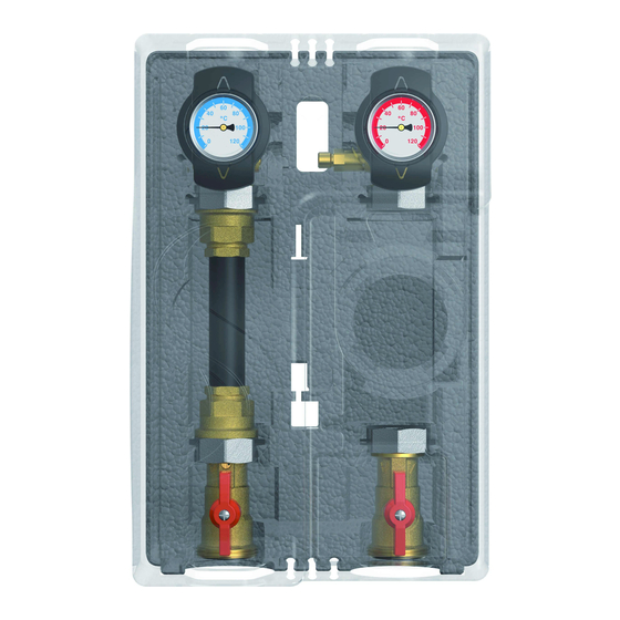
2 . 3 A U S S T A T T U N G Vorlauf zum Verbraucherkreis Vorlauf-Kugelhahn mit Tauchhülse und Ganzmetall-Thermometer Vorlauf vom Wärmeerzeuger Rücklauf zum Wärmeerzeuger Rücklauf-Kugelhahn Vorlauf-Kugelhahn aufstellbare Schwerkraftbremse (19,6 mbar) Einbausatz für Wärmemengenzähler (¾" AG x 110 mm oder 1" AG x 130 mm) funktionsoptimierte Design-Dämmung Rücklauf vom Verbraucherkreis Rücklauf-Kugelhahn mit Tauchhülse und Ganzmetall-Thermometer... -
Page 5: Schwerkraftbremse
P U M P E N G R U P P E U N G E M I S C H T D N 2 5 M I T E I N B A U S A T Z F Ü R W M Z 2 . -
Page 6: Technische Zeichnung
3 T E C H N I S C H E Z E I C H N U N G Alle Angaben in mm 4 V O R S C H R I F T E N / N O R M E N / R I C H T L I N I E N Die Pumpengruppe darf nur in Heizungskreisen unter Berücksichtigung der in dieser Anleitung angegebenen technischen Grenzwerte verwendet werden. -
Page 7: Technische Daten
P U M P E N G R U P P E U N G E M I S C H T D N 2 5 M I T E I N B A U S A T Z F Ü R W M Z 5 T E C H N I S C H E D A T E N A B M E S S U N G E N Achsabstand... -
Page 8: Sicherheitshinweise
6 S I C H E R H E I T S H I N W E I S E Die Installation und Inbetriebnahme sowie der Anschluss der elektrischen Komponenten setzen Fachkenntnisse voraus, die einem anerkannten Berufsabschluss als Anlagenmechaniker/in für Sanitär-, Heizungs- und Klimatechnik bzw. einem Beruf mit vergleichbarem Kenntnisstand entsprechen [Fachmann]. -
Page 9: Montage- Und Betriebsanleitung / Installation
P U M P E N G R U P P E U N G E M I S C H T D N 2 5 M I T E I N B A U S A T Z F Ü R W M Z 7 M O N T A G E - U N D B E T R I E B S - A N L E I T U N G / I N S T A L L A T I O N Die Pumpengruppe kann entweder auf einem Verteiler oder auf einer Wandhalterung... -
Page 10: Montage Auf Wandhalter
7 . 2 M O N T A G E A U F W A N D H A LT E R Die Premium Wandhalterung für Pumpengruppen ist nicht im Lieferumfang enthalten (KBN: C2PWH). Alle Angaben Bestimmen Sie den Montageort. in mm Eine Bohrschablone finden Sie auf der Pappe neben der Pumpengruppe (siehe Abbildung links). -
Page 11: Montage Auf Stockschrauben
P U M P E N G R U P P E U N G E M I S C H T D N 2 5 M I T E I N B A U S A T Z F Ü R W M Z 7 . -
Page 12: Inbetriebnahme / Funktionsprüfung / Außerbetriebnahme
8 I N B E T R I E B N A H M E / F U N K T I O N S P R Ü F U N G / A U S S E R B E T R I E B N A H M E Verrohren Sie die Pumpengruppe mit der Anlage. -
Page 13: Inbetriebnahme Wärmemengenzähler Und Sensorik
P U M P E N G R U P P E U N G E M I S C H T D N 2 5 M I T E I N B A U S A T Z F Ü R W M Z 8 . -
Page 14: Wartung
Reduzierstück ¼” AG sd x M12x1.5 AG bzw. ¼” AG sd x M10x1 IG YCOQ00059 Pumpeneinleger für Dämmung, notwendig bei Ersatz COSMO CPH durch CPH 2.0 Pumpe DN 25, 1½" AG x 180 mm C2WSPG Winkelstecker mit 2 m Kabel, passend für Grundfos / Wilo-Pumpen und COSMO CPH 2.0... -
Page 15: Pflegehinweise
P U M P E N G R U P P E U N G E M I S C H T D N 2 5 M I T E I N B A U S A T Z F Ü R W M Z 1 0 P F L E G E H I N W E I S E Es sind keine Pflegehinweise für dieses Produkt vorhanden. -
Page 16: Kontaktdaten
Farbabweichungen sind auch aus drucktech- nischen Gründen nicht auszuschließen. Modell- und Produktansprüche können nicht geltend gemacht werden. Im Rahmen der zur Zeit gültigen gesetzlichen Bestimmungen des Kaufvertragsrechts (BGB hinsichtlich Mängelgewährleistungsansprüche) gilt für COSMO eine Verjährungsfrist von 5 Jahren ab Lieferung. - Page 17 P U M P E N G R U P P E U N G E M I S C H T D N 2 5 M I T E I N B A U S A T Z F Ü R W M Z...
- Page 19 G U T E S K L I M A B E S S E R L E B E N I NSTA L L AT ION A ND O P ERATIO N IN S TRUCTIO NS U NMI XED P U M P GROU P D N 25 W I TH I NSTAL LAT I ON KIT FOR HEAT F LOW MET ER IN S T RUC T ION S F O R U S E U NM I XED P U MP G ROU P D N 25...
- Page 20 11 Contact details 12 Guarantee / Warranty / Availability guarantee Item no. 9936112CSM01-mub-ml – Version V06 – Issued 2018/07 Translation of the original instructions We reserve the right to make technical changes without notice! Printed in Germany – Copyright by COSMO GmbH...
-
Page 21: Scope Of Delivery
U N M I X E D P U M P G R O U P D N 2 5 W I T H I N S T A L L A T I O N K I T F O R H E A T F L O W M E T E R 2 S C O P E O F D E L I V E R Y Carefully read these instructions before installation and commissioning. -
Page 22: Equipment
Reducer ¼” ext. thread, self-sealing x M10 x 1 int. thread The pump group is prepared for the use of pumps with the connection dimensions 1½" ext. thread x 180 mm. If other pumps than those intended by COSMO are used, it may be necessary to adapt the insulation elements. -
Page 23: Check Valve
U N M I X E D P U M P G R O U P D N 2 5 W I T H I N S T A L L A T I O N K I T F O R H E A T F L O W M E T E R 2 . -
Page 24: Technical Drawing
3 T E C H N I C A L D R A W I N G All dimensions in mm 4 R E G U L A T I O N S / S T A N D A R D S / D I R E C T I V E S The pump group may only be used in heating circuits taking into consideration the technical limit values indicated in these instructions. -
Page 25: Technical Data
U N M I X E D P U M P G R O U P D N 2 5 W I T H I N S T A L L A T I O N K I T F O R H E A T F L O W M E T E R 5 T E C H N I C A L D A T A D I M E N S I O N S Centre distance... -
Page 26: Safety Instructions
6 S A F E T Y I N S T R U C T I O N S The installation and commissioning as well as the connection of electrical components require technical knowledge commensurate with a recognised vocational qualification as a fitter for plumbing, heating and air conditioning technology, or a profession requiring a comparable level of knowledge [specialist]. -
Page 27: Instructions For Use / Installation
U N M I X E D P U M P G R O U P D N 2 5 W I T H I N S T A L L A T I O N K I T F O R H E A T F L O W M E T E R 7 I N S T R U C T I O N S F O R U S E / I N S T A L L A T I O N The pump group can be mounted either on a distribution manifold or on a wall bracket... -
Page 28: Installation On A Wall Bracket
7 . 2 I N S T A L L A T I O N O N A W A L L B R A C K E T The Premium wall bracket for pump groups is not included in the scope of delivery (KBN: C2PWH). -
Page 29: Installation On Stair Bolts
U N M I X E D P U M P G R O U P D N 2 5 W I T H I N S T A L L A T I O N K I T F O R H E A T F L O W M E T E R 7 . -
Page 30: Commissioning / Function Test / Decommissioning
8 C O M M I S S I O N I N G / F U N C T I O N T E S T / D E C O M M I S S I O N I N G Connect the pump group to the installation by using the pipes. -
Page 31: Commissioning Of The Heat Flow Meter And The Sensors
U N M I X E D P U M P G R O U P D N 2 5 W I T H I N S T A L L A T I O N K I T F O R H E A T F L O W M E T E R 8 . -
Page 32: Maintenance
Reducer ¼” ext. thread, self-sealing x M12x1.5 ext. thread or ¼” ext. thread, self-sealing x M10x1 int. thread YCOQ00059 Pump insert for insulation, necessary when replacing COSMO CPH by CPH 2.0 Pump DN 25, 1½" ext. thread x 180 mm C2WSPG Right-angle plug with 2 m cable, suitable for Grundfos / Wilo pumps and COSMO CPH 2.0... -
Page 33: Care Instructions
U N M I X E D P U M P G R O U P D N 2 5 W I T H I N S T A L L A T I O N K I T F O R H E A T F L O W M E T E R 1 0 C A R E I N S T R U C T I O N S There are no care instructions for this product. -
Page 34: Contact Details
Model and product claims cannot be asserted. Within the scope of the currently valid legal provisions of the purchase contract law (German Civil Code (BGB) in regard to warranty claims for defects), a limitation period of 5 years from delivery applies to COSMO. - Page 35 U N M I X E D P U M P G R O U P D N 2 5 W I T H I N S T A L L A T I O N K I T F O R H E A T F L O W M E T E R...
- Page 36 G U T E S K L I M A B E S S E R L E B E N C O S M O GMBH Brandstücken 31 · 22549 Hamburg i n f o @ c o s m o - i n f o . d e w w w .
Need help?
Do you have a question about the C2PGUWMZ and is the answer not in the manual?
Questions and answers