Table of Contents
Advertisement
Quick Links
Remote I/O R3 Series
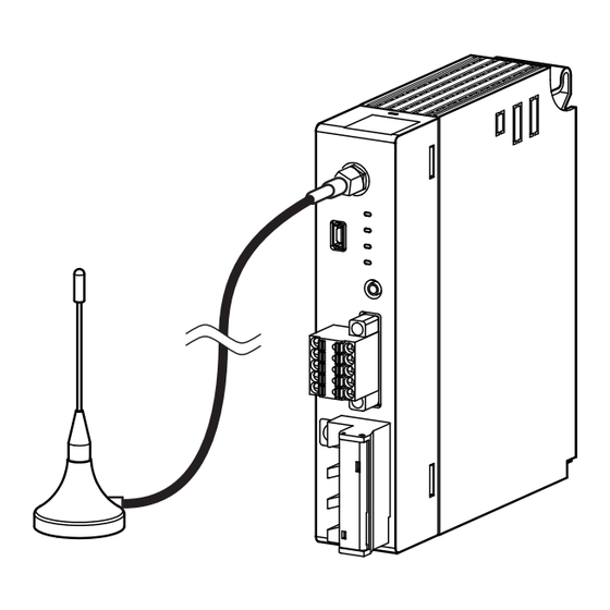
MODBUS INTERFACE MODULE
(Modbus Wired Communication, Modbus-RTU Transparent
900 MHz Band Devices Use)
27.5 ( 1.08 )
280
( 11.02 )
154
( 6.06 )
mm (inch)
MODEL: R3–NMW1F-[1][2]
ORDERING INFORMATION
• Code number: R3-NMW1F-[1][2]
Specify a code from below for each [1] and [2].
(e.g. R3-NMW1F-N/E/Q)
• Specify the specification for option code /Q
(e.g. /C01)
[1] POWER INPUT
N: No power supply
AC Power
M2: 100 – 240 V AC (Operational voltage range 85 – 264 V,
47 – 66 Hz)*
DC Power
R: 24 V DC
(Operational voltage range 24 V ±10 %, ripple 10 %p-p max.) *
* Not selectable for use with independent power modules or
network modules with the internal power input options.
[2] OPTIONS (multiple selections)
Antenna
/S: Sleeve antenna
/E: Rooftop antenna
Other Options
blank: none
/Q: Option other than the above (specify the specification)
http://www.m-system.co.jp/
SPECIFICATIONS OF OPTION: Q
COATING (For the detail, refer to M-System's web site.)
/C01: Silicone coating
/C02: Polyurethane coating
/C03: Rubber coating
FUNCTIONS & FEATURES
• Equipped with 900 MHz band wireless device
• Uses Modbus-RTU protocol wired com. as main network,
and monitors I/O signal with wireless
• Available to use wireless device as main network
• Wireless deive incorporates a module conforming to FCC
part 15, and can be used within the United States only.
• Modbus-RTU gateway function available, outputs data
received with wireless to wired network
RELATED PRODUCTS
For the details of the wireless device related products,
please refer to M-system website.
• PC configurator software (model: R3CON)
Downloadable at M-System's web site.
A dedicated cable is required to connect the module to the
PC. Please refer to the internet software download site or
the users manual for the PC configurator for applicable
cable types.
Maintenance software
Maintenance console: MH920 Console for International
(model: MH920CI) (OKI)
(Maintenance software is downloadable at M-System's web
site.)
Coaxial cable
• 7.5 m extension cable for rooftop antenna (model: CX-
SAC0SAD0Q0750) (OKI)
PACKAGE INCLUDES...
• Terminating resistor (110 Ω, 0.25 W)
GENERAL SPECIFICATIONS
Connection
Wireless network: SMA coaxial connector
Wired network: Tension clamp terminal (Front Twin
connection)
Applicable wire size: 0.2 - 1.5 mm
Internal bus: Via the Installation Base (model: R3-BSx)
Internal power: Via the Installation Base (model: R3-BSx)
Power input, RUN contact output: M3 separable screw
terminal (torque 0.5 N·m)
Maintenance: Mini USB type B female connector
Screw terminal: Nickel-plated steel
Isolation: Modbus to internal bus or internal power or
R3-NMW1F SPECIFICATIONS
MODEL: R3-NMW1F
2
, stripped length: 10 mm
ES-8286 Rev.0 Page 1/12
Advertisement
Table of Contents

Summary of Contents for M-system R3 Series
-
Page 1: Ordering Information
MODEL: R3-NMW1F Remote I/O R3 Series SPECIFICATIONS OF OPTION: Q COATING (For the detail, refer to M-System's web site.) /C01: Silicone coating MODBUS INTERFACE MODULE /C02: Polyurethane coating (Modbus Wired Communication, Modbus-RTU Transparent /C03: Rubber coating 900 MHz Band Devices Use) FUNCTIONS &... -
Page 2: Modbus Communication
Max. Tx power: 20 mW Bandwidth: 400 kHz STANDARDS & APPROVALS Modulation: GFSK Module conforming to FCC Part 15 incorporated Baud rate: Max. 100 kbps Channel: 1 - 43ch Security: 128 bit AES R3-NMW1F SPECIFICATIONS ES-8286 Rev.0 Page 2/12 http://www.m-system.co.jp/... - Page 3 Standard / Changing frequency • delaytime middle / Standard Changing frequency • delaytime large Network join mode V3-compatible mode / Fast join mode V3-compatible mode Retry times before route switching 1 to 3 (times) R3-NMW1F SPECIFICATIONS ES-8286 Rev.0 Page 3/12 http://www.m-system.co.jp/...
-
Page 4: External View
U (+) Power input (+) Unused RUN- RUN – U(+) V (−) Power input (−) Unused RUN – RUN contact output – RUN – RUN contact output – V(-) Unused Unused Functional earth Unused R3-NMW1F SPECIFICATIONS ES-8286 Rev.0 Page 4/12 http://www.m-system.co.jp/... - Page 5 Function code is not allowable for the slave Illegal Data Address Address is not available within the slave Illegal Data Value Data is not valid for the function Slave Device Failure Acknowledge Slave Device Busy Negative Acknowledge Memory Parity Error R3-NMW1F SPECIFICATIONS ES-8286 Rev.0 Page 5/12 http://www.m-system.co.jp/...
- Page 6 • Writing to Coil (0X) and Holding Registers (4X) is only available with either Wireless or Modbus communication. It is available to change the con guration with Con gurator Software (model: R3CON). Factory default setting is Modbus communication. R3-NMW1F SPECIFICATIONS ES-8286 Rev.0 Page 6/12 http://www.m-system.co.jp/...
- Page 7 Basically, 0 to 100% of the selected I/O range is converted into 0 to 10000 (binary). -15 to 0 % is a negative range represented in 2’s complement. In case of R3-US4, -10 to 0% is a negative range represented in 2's complement. R3-NMW1F SPECIFICATIONS ES-8286 Rev.0 Page 7/12 http://www.m-system.co.jp/...
- Page 8 Higher 16 bits ■ 16-POINT DISCRETE DATA (models: R3-DA16, DC16, etc.) Input 1 (Output 1) Input 2 (Output 2) Input 3 (Output 3) Input 16 (Output 16) 0 : OFF 1 : ON R3-NMW1F SPECIFICATIONS ES-8286 Rev.0 Page 8/12 http://www.m-system.co.jp/...
- Page 9 6 – M3 SCREW TERMINAL COVER 45 (1.77) 109 (4.29) 27.5 (1.08) [200 (7.87)] • WITH ROOFTOP ANTENNA Dia.3 (.12) Dia.1.2 (.05) POSITIONING GUIDE [2500 (98.43)] Dia.27 (1.06) TERMINAL COVER (.75) 109 (4.29) R3-NMW1F SPECIFICATIONS ES-8286 Rev.0 Page 9/12 http://www.m-system.co.jp/...
- Page 10 JACK INTERNAL POWER Isolation To Other Modbus Devices Control Circuit RUN + RUN CONTACT OUTPUT RUN − U (+) POWER INPUT V (–) *FE1 * Not provided with ‘No Power Supply’ type module. R3-NMW1F SPECIFICATIONS ES-8286 Rev.0 Page 10/12 http://www.m-system.co.jp/...
-
Page 11: System Configuration Examples
(model: R3-NMW1F) LAN cable (Gateway) Max. number of modules: 31 Wireless Gateway (model: WL40EW2F) Modbus/Master RS–485 slave device slave device slave device Modbus Interface Module (model: R3-NMW1F) (slave) Max. number of modules: 31 R3-NMW1F SPECIFICATIONS ES-8286 Rev.0 Page 11/12 http://www.m-system.co.jp/... - Page 12 MODEL: R3-NMW1F Specifications are subject to change without notice. R3-NMW1F SPECIFICATIONS ES-8286 Rev.0 Page 12/12 http://www.m-system.co.jp/...


Need help?
Do you have a question about the R3 Series and is the answer not in the manual?
Questions and answers