
Related Manuals for Veigel BLF00006


Summary of Contents for Veigel BLF00006
- Page 1 Installation and Operating Instructions Universal electronics kit for the left-foot accelerator pedal, VEA version Art. no. BLF00006 www.veigel-automotive.de...
- Page 2 Document no. 250554 Created 2019-09-26 Name Schulz Subject to technical modifications without prior Revised 2021-02-22/Sch. notification and to errors. Reproduction, even in part, only permitted with Version 7 permission from Veigel GmbH + Co. KG.
-
Page 3: Table Of Contents
Contents Contents Contents .....................1-1 Revision history ....................1-2 Blank page for your notes ................... 1-4 General information ..................2-1 General safety information .................. 2-1 Product description ...................3-1 Function ......................3-1 Type plate ......................3-1 Scope of delivery ....................3-2 Block diagram ..................... 3-3 Intended use ....................... -
Page 4: Contents
Contents Revision history Edition Revisions Chapter 01 / 2019-09-26 Initial version 02 / 2020-01-28 Editorial revision 03 / 2020-03-12 Editorial revision 04 / 2020-03-25 Editorial revision 05 / 2020-07-22 Editorial revision (point 5 removed) 06 / 2020-07-23 Chapter 4 replaced 07 / 2021-02-22 Chapters 4 and 5 corrected... - Page 5 ATTENTION! This symbol refers to important additional information. NOTE This symbol refers to tips and recommendations. Veigel hotline Veigel GmbH + Co. KG Telephone: +49 (0) 7941 60585-0 Verrenberger Weg 36 Fax: +49 (0) 7941 60585-20 74613 Öhringen, Germany...
-
Page 6: Blank Page For Your Notes
Contents Blank page for your notes... -
Page 7: General Information
If the driving aid is installed in an authorised workshop, the installation re- cord must be filled in (see appendix). If it is installed at the factory, a sep- arate installation record will be prepared and archived at the Veigel factory. - Page 8 General information Observe the following in particular as a user: • Comply with generally accepted codes of practice when using and oper- ating the driving aid! ATTENTION! • Observe the applicable accident prevention and safety provisions when op- erating the driving aid! •...
-
Page 9: Product Description
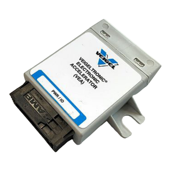
The electronic left-foot accelerator meets the stringent provisions laid down by the automotive industry. Do not install and operate the VEA-type electronics kit in Groupe PSA vehicles. ATTENTION! Type plate Veigel GmbH + Co. KG 74613 Öhringen Type: Version: Type designation: xxxxxx-xxx Factory no.: BLF00006 Article no.:... -
Page 10: Scope Of Delivery
Product description Scope of delivery Fig. 3-1 Scope of delivery (example) Item Description Art. no. VEA electronics kit 230645 VEA left-foot accelerator cable 230410 Accelerator pedal module 230124 Sticker 250458 Holder 101510... -
Page 11: Block Diagram
Product description Block diagram Switchover button Original accelerator pedal Teach-in adapter Veigel additional accelerator pedal Power supply... -
Page 12: Intended Use
Product description Fig. 3-2: Electronic left-foot accelerator installed Intended use Use the VEA universal kit to install the accelerator in automatic vehicles that do not have a vehicle-specific conversion kit. -
Page 13: Assembly
The tightening torques as specified by the vehicle manufacturer apply when converting vehicles using Veigel driving aids. Unless otherwise stated in the text, the usual DIN tightening torques provided ATTENTION! in the table below apply for Veigel parts. Coarse thread Fine thread Tightening torque (Nm) -
Page 14: Installing The Additional Accelerator Pedal
Assembly Installing the additional accelerator pedal Create a vehicle-specific holder to enable you to assemble the second additional accelerator pedal in the vehicle. See Fig. 4-1 to 4-3 for examples of such a holder and how to fasten it. Fasten this holder to the available screw points as a first preference or, alternatively, to new drill holes you have made in the vehicle. - Page 15 Assembly Installing the additional accelerator pedal See Fig. 4-4 for examples of how to install the fastenings for the ad- ditional accelerator pedal. Fig. 4-4: Example installation...
-
Page 16: Installing The Additional Accelerator Pedal
Assembly Installing the additional accelerator pedal See Fig. 4-5 to 4-7 for examples of how to install the fastenings for the additional accelerator pedal. Fig. 4-5: Example installation Fig. 4-6: Example installation Fig. 4-7: Example installation... -
Page 17: Connecting The Universal Adapter
Assembly Connecting the universal adapter... -
Page 18: Accelerator Pedal Signal/Pin Assignment
Assembly Accelerator pedal signal/pin assignment To find out how the pins and signals are assigned, use a multimeter to test the cables on the original accelerator module. The following signals are usually present: 2x supply voltage, 2x signal cables+, 2x earth. You can enter the signals you have measured in the table printed below. -
Page 19: Assembling The Vea
Assembly Assembling the VEA Connect the plug to the VEA box. F a s t e n a l l l o o s e c a b l e s and check that the relevant plugs are seated sec urely. Re-attach the trim panel to the dashboard in the driver's side footwell. -
Page 20: Teaching In The Vea
Assembly Teaching in the VEA The teach-in process must have been completed successfully prior to commissioning. ATTENTION! 1. Ignition off 2. Plug the TEACH-IN adapter into the black mating connector. 3. Ignition on 4. Status LED flashes slowly (ready for teach-in) Fig. -
Page 21: Button With Integrated Status Led
Assembly Button with integrated status LED Drill a hole with a minimum 19.2 mm diameter in a suitable place. Note the length of the button and plan for a minimum depth of 40 mm. Insert and screw down the button, then connect it to the wiring har- ness supplied. -
Page 22: Prosthetics Guard Holder
Assembly Prosthetics guard holder It is strongly recommended to attach a prosthetics guard between the brake pedal and the right-foot accelerator pedal if the driver is going to use the left- NOTE foot accelerator pedal. This stops the right foot from getting stuck under and blocking the brake pedal. -
Page 23: Operation
Operation Operation Take a moment to familiarise yourself with the converted vehicle. It may be advisable to visit a driver training area to adapt to the unfamiliar mode of operation. The driving aid is easy to operate and its electronic control unit complies with the highest safety standards of the automotive industry. -
Page 24: Operation Of The Electronic Switchover
Operation Operation of the electronic switchover When delivered, the VEA is in Mode 1. Mode 1 = the original accelerator pedal is active each time the vehicle restarts. NOTE It is possible to set the VEA to Mode 2 instead. Mode 2 = the last accelerator pedal used remains stored. - Page 25 Operation When delivered, the VEA is in Mode 1. Mode 1 = the original accelerator pedal is active each time the vehicle restarts. NOTE It is possible to set the VEA to Mode 2 instead. Mode 2 = the last accelerator pedal used remains stored. In Mode 1 1.
- Page 26 Operation Change operation mode, Mode 1 and Mode 2 are only available after assembly. NOTE In Mode 2 1. Ignition on 2. Status LED flashes quickly once (LED indicating that the original pedal is active is not lit) (LED indicating that the additional pedal is active flashes) 3.
-
Page 27: Safety Information
The responsible repair shop should contact the system manufacturer in case of any doubt. (For details of the Veigel GmbH + Co. KG hotline, see page 1-3.) Arrange for any irregularities to be examined by a workshop. - Page 28 Operation Blank page for your notes...
-
Page 29: Maintenance And Care
Maintenance and care Maintenance and care Safety information Maintenance and repair work on the devices may only be performed by authorised and appropriately trained staff! ATTENTION! Arrange for functional faults to be remedied immediately by a specialist workshop. Only personnel authorised by us may open the control, otherwise any warranty claim shall be invalidated. -
Page 30: Transport, Storage And Disposal
Transport, storage and disposal Transport, storage and disposal Transport and storage Transport and storage are only permitted in the original packaging. Disposal Always comply with national and regional waste disposal directives. We ensure that the majority of the materials used to make our products are re- cyclable, right from the design phase. -
Page 31: Installation Record
Installation record Installation record This record will be completed if the driving aid is installed at a specialist workshop. If it is installed at the Veigel factory, a separate installation record will be pre- pared and archived there. Customer: Installation date:... -
Page 32: Blank Page For Your Notes
Installation record Blank page for your notes... - Page 33 Installation record Blank page for your notes...
- Page 36 Veigel GmbH + Co. KG Verrenberger Weg 36 74613 Öhringen, Germany tel. +49 (0) 7941 60585 0 fax +49 (0) 7941 60585 20 info@veigel-automotive.de www.veigel-automotive.de A SOLUTION FOR EVERY VEHICLE...
Need help?
Do you have a question about the BLF00006 and is the answer not in the manual?
Questions and answers