Table of Contents
Advertisement
Quick Links
INSTALLATION GUIDE - SI 1806 kit - SI 1821 kit
RECOMMENDED ACCESSORIES
ACC00220
ACC00213
ACC00801
ACC00125
ACC00215
N915-04_edition 10_34.indd 1
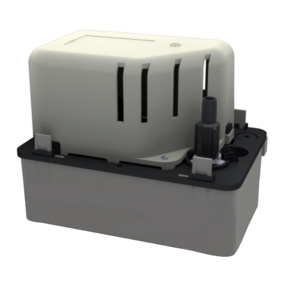
CONDENSATE REMOVAL PUMP
Rubber condensate outlet adaptor.
Ø 10 to Ø 20 mm.
Ø 10 x10 mm straight connectors
Replacement check valve.
For Ø10 mm int. (3/8") tube.
PVC hose Ø 10mm int, 25 m long
3 condensate self-sealing evacuation
connectors, Ø 10 mm int.
SAUERMANN UK Ltd.
Units 7 – 9, Trident Business Park - Amy Johnson Way Blackpool
Lancashire FY4 2RP - United Kingdom
Email: sales@sauermann-uk.com
®
24/08/2010 16:21:23
Advertisement
Table of Contents

Related Manuals for sauermann SI 1806 kit


Summary of Contents for sauermann SI 1806 kit
- Page 1 ® CONDENSATE REMOVAL PUMP INSTALLATION GUIDE - SI 1806 kit - SI 1821 kit RECOMMENDED ACCESSORIES Rubber condensate outlet adaptor. ACC00220 Ø 10 to Ø 20 mm. ACC00213 Ø 10 x10 mm straight connectors Replacement check valve. ACC00801 For Ø10 mm int. (3/8”) tube.
- Page 2 PACK CONTENTS A Condensate pump E 5 m Ø 10 mm int. hose Kit SI1806: SI 1805 pump Mains cable Kit SI1821: SI 1820 pump G Safety switch cable B Ø 20 mm pipe adaptor H Check valve C Wall Plugs Ø...
- Page 3 INSTALLING THE PUMP To ease installation, the tank on the pump is reversible i.e. this can be fitted to accept the condensate drain pipework from the boiler to either the left or right hand side. Left Right Consideration should also be taken of the siting of the pump to prevent noise emissions and vibrations. To ensure sufficient ventilation to the motor the area around the pump should be left unobstructed.
- Page 4 CONDENSATE RUNS NOTE As the condensate from the boiler is gravity fed into the condensate pump it is essential that the pump is sited lower than the boiler. For termination options see frame 6. STORE BOILER WALL HUNG BOILER FLOOR STANDING BOILER NOTE. NOTE.
- Page 5 CONDENSATE PIPE TERMINATION CONFIGURATIONS EN12056.1 : European norm for “Gravity drainage systems inside buildings” §4.5- Drains that carry boiler’s condensates must be resistant to acidic water (pH<6.5) Note: Frozen discharge pipes will make the pump run continuously. INTERNAL TO SINK WASTE UPSTREAM OF SINK WASTE TRAP External wall Sink constitutes air break Open end of pipe BOILER direct into gulley...
- Page 6 CONDENSATE PIPE TERMINATION CONFIGURATIONS... continued TERMINATION INTO PIPE DRAIN DON’T Frozen discharge pipes would make the pump run continuously Fall Pipe Fall Pipe Drain Drain BOILER BOILER PUMP PUMP Pipe below pump level TERMINATION TO SOAK AWAY DON’T Frozen discharge pipes would make the pump run continuously External wall External...
- Page 7 WIRING Note. The wiring for the safety switch contacts MUST be used. Choose the wiring diagram from those below which matches that of the appliance. If in doubt contact the appliance manufacturer. Wiring diagram provided depict the additional wiring needed for the inclusion of the condensate pump. This scheme may be incorporated into the existing wiring centre junction box, fused spur etc.
- Page 8 MAINTENANCE AND SERVICING The inside of the pump kit should be cleaned regularly at every annual service of the appliance. Note. Before any maintenance the pump must be isolated from the power supply. When disconnecting the inlet and outlet pipe work from the pump make provision to capture any condensate which may be still contained within the pipe work.
Need help?
Do you have a question about the SI 1806 kit and is the answer not in the manual?
Questions and answers