Table of Contents
Advertisement
HSGW-Gen2-V1
IP Alarm System
User Manual
Certified by Telefication BV
Manufacturer: Climax Technology, Taiwan
Type: HSGW-Gen2-V1
Compliance with Standard:
EN50131-3:2009 / EN50131-6:2017 /
EN50131-5-3:2017 / EN50130-4:2011+A1:2014 /
EN50131-10:2014 / EN50136-2:2013 /
EN 50130-5:2011, Security Grade 2
August 19, 2022
Environmental Class II
CIE Type A
Advertisement
Table of Contents

Subscribe to Our Youtube Channel
Related Manuals for Climax Technology HSGW-Gen2-V1


Summary of Contents for Climax Technology HSGW-Gen2-V1
- Page 1 HSGW-Gen2-V1 IP Alarm System User Manual Certified by Telefication BV Manufacturer: Climax Technology, Taiwan Type: HSGW-Gen2-V1 Compliance with Standard: EN50131-3:2009 / EN50131-6:2017 / EN50131-5-3:2017 / EN50130-4:2011+A1:2014 / EN50131-10:2014 / EN50136-2:2013 / EN 50130-5:2011, Security Grade 2 August 19, 2022 Environmental Class II...
-
Page 2: Table Of Contents
Table of Contents INTRODUCTION _________________________________________________________________________ 1 1.1. S _____________________________________________________________________ 1 YSTEM PECIFICATION 1.2. P ________________________________________________________________________ 3 ACKAGE ONTENT PANEL INFORMATION ___________________________________________________________________ 4 2.1. I : ____________________________________________________________________ 4 DENTIFYING THE PARTS 2.2. T : _______________________________________________________________________ 5 ... - Page 3 8.2 V ___________________________________________________________________________ 35 ISTORY 8.3 H ________________________________________________________________________________ 36 ISTORY 8.4. R __________________________________________________________ 37 EQUESTING A IRMWARE PGRADE 8.5 S _______________________________________________________ 37 YSTEM PERATION AND AINTENANCE 8.5.1 Device Test ________________________________________________________________________ 37 8.5.2 IP/GSM reporting __________________________________________________________________ 37 ...
-
Page 4: Introduction
1. Introduction HSGW-Gen2-V1 is a fixed wall mounting wireless alarm system control panel. It is designed to protect your home by forming an alarm system with various wireless sensors. When an intruder is detected, the wireless sensor will transmit signal to the control panel to raise an alarm and report to the Central Monitoring Station. - Page 5 Supervision Programmable time frame for inactivity alert Special Function Tamper Protection GSM Standards Compiles with CE standards EN Classification EN Grade 2 Class II Alarm Transmission Path Dual Path: DP1 (EN50136-1:2012) Alarm Report Server (ARS), Fibro, OH200, MasterMind, Manitou, Supported RCT MicroKey and SIA DC 09 Mode Acknowledgement...
-
Page 6: Package Content
185mm x 185mm x 50mm Weight 580g (Includes backup battery) 1.2. Package Content 1 x HSGW-Gen2-V1 Control Panel 1 x AC Power Cord for Built-in S.P.S (12V 1.5A) 1 x Installation and Instruction Manual 4 x Screws and Wall Plug for wall mounting... -
Page 7: Panel Information
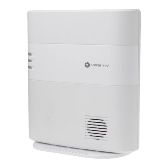
2. Panel Information 2.1. Identifying the parts: Front Cover view Side View Back View LED 1 - Area 1 (Green/Red) Full Arm mode - Red lighting up Mounting Bracket Home/1/2/3 mode - Red flashing Disarm mode - Green lighting up Walk Test or Learning mode - Green flashing LED 2 - Area 2 (Green/Red) Full Arm mode - Red lighting up... -
Page 8: The Power Supply
hooked onto the mounting bracket. When the panel is removed from the mounting bracket, the tamper switch will be activated and the panel will send a tamper open signal to remind the user of this condition. Power Cord Inlet Wiring Hole Fixing Screws x 2 Wall Mounting Holes x 2 Mounting Bracket... -
Page 9: Getting Started
3. Getting Started Read this section of the manual to learn how to set up your HSGW-Gen2-V1 Panel and program System Settings over the Web page. 3.1. Hardware Installation The panel can be either fixed on the wall or placed on deskop. For the panel to meet requirements of the applicable EN standard, wall mounting installation must be used. - Page 10 Wall Mounting: (EN Compliance) Use the mounting holes as template, mark mounting locations on the wall. Secure the mounting bracket onto the wall by tightening the 2 screws through the wall mounting holes. III. Mount the Control Panel with the hooks of the mounting bracket latched onto the back cover of the the panel, and push it downward until you hear a clicking sound.
-
Page 11: Connect To Panel
3.2. Connect to Panel Step 1. Connect to https://alarmadmin.alarm.com/mobile/Default.aspx and log in with provided username and password Step 2. In the main page, select “Find Customer”. - Page 12 Step 3. Select “Recent Customers” to expand. Step 4. Select the panel account you with to access. <IMPORTANT NOTE> The Installer Access function must be granted by user first to enable installer functions. By default, Installer Access is granted for 6 hours per session. ...
- Page 13 Step 5. You will access the panel user’s customer information. <IMPORTANT NOTE> The Installer Access function must be enabled by user first, otherwise login attempt will fail. To enable user access, ask the user to follow steps below: Go to https://www.alarm.com/login.aspx and login with the user account information.
- Page 14 II. Select “Profile” – “Manage Logins” – “Edit Dealer Setting”. III. Set “Installer Access” to “”On” then save the setting. <IMPORTANT NOTE> After 20 minutes of inactivity on the Customer App, the user’s session will timeout and the user will need to log in again to use any functions.
-
Page 15: Device Management
4. Device Management Under Customer Info page, select “Equipment” to for device management. 4.1. Learning Step 1. Under Equipment page, select “Add Devices”. - Page 16 Step 2. Select the device type from the menu. For example, select “Sensor” Step 3. The Panel will begin to enter learning mode. Step 4. After the panel has entered learning mode, activate the device to send signal to panel.
-
Page 17: Sensor Management
Step 5. When the panel receives sensor signal, the sensor info will be displayed on webpage. Add any additional devices and click “Exit and Edit” to proceed to next step. 4.2. Sensor Management The Sensor Management page can be accessed either after finish adding new device, or by selecting “Sensor”... - Page 18 The sensor partition can be edited by selecting “Advanced Sensor Settings”. Choose new partition for the device and click “Save Changes” to confirm. Click “Add Sensor” to learn new sensors, see 4.1. Learning for detail. Click “Delete Sensor” to remove device, you will enter device removal page. Select the device to be removed and click “Send Command”...
- Page 19 III. When the panel receives signal from panel, the webpage info will be updated with sensor info. After finish testing all sensor, click End Walk Test to exit Walk Test Mode.
-
Page 20: Panel Management
5. Panel Management Under Customer Info page, select “Panel/Partitions” – “Panel Management” to access panel management page. Click each option to expand the setting for configuration <NOTE> For EN Grade 2 Compliance, the following Panel Management Settings must be configured: ... -
Page 21: Arming Setting
5.1. Arming Setting The Arming Setting includes parameters which affects system mode change function. Click “Edit” to modify each setting. Arm Fault Type: Select how the system should respond when it is being armed under fault condition. Confirm: The panel will first display a “Mode Change Fault” message and emit 2 beeps. -
Page 22: Sound Setting
to Disarm mode and no alarm is activated. If the Control Panel is not disarmed before the Entry Delay Timer expires, the alarm will be activated and the panel will send report. Entry Delay 2 for Arm Away: Set Entry Delay Timer 2 for Away Arm mode. When a sensor set to Start Entry Delay 2 is triggered under Away Arm mode, the control panel will begin Entry Delay Timer countdown according to duration set with this option If the Control Panel is disarmed before the Entry Delay Timer expires, the panel returns... -
Page 23: Monitoring Station Settings
Entry Delay Sound for Arm Stay: this is for you to decide whether the Control Panel sounds count-down beeps and volume of beep during the entry delay time in Arm Stay mode. Exit Delay Sound for Arm Stay: this is for you to decide whether the Control Panel sounds count-down beeps and volume of beep during the exit delay timer in Arm Stay mode. -
Page 24: Timer
5.4. Timer Supervision Check: Select to enable or disable system supervision function. When ON is selected, the Control Panel will monitor the accessory devices according to the supervision signal received. Supervision Timer: The Control Panel monitors accessory devices according to the supervision signal transmitted regularly from the device. -
Page 25: User Codes
5.6. User Codes The User Codes setting allows configuration of access codes stored in the panel. Edit Panel User Codes: Select to edit the panel user code, then click “Manage User Code” to access the panel user interface and program User setting. NOTE: Only 6 six user codes are available on EN Grade 2 Compliant panels ... -
Page 26: Wi-Fi Setting
5.7. Wi-Fi Setting The Wi-Fi setting allows you to check panel broadband setting, and determine whether Ethernet connection should be bypassed. <NOTE> For EN Grade 2 Compliance, Ethernet Bypass must be set to “Disable”: 5.8. Miscellaneous Setting The Miscellaneous Setting includes following setting option: ... -
Page 27: System Settings
6. System Settings 6.1 Central Station Reporting Please follow the steps below to enable Central Station reporting and choose which events are reported to a central station. From the “Customer Info” page, select “Monitoring. -
Page 28: Enabling En Grade 2/Incert Monitoring
Under Monitoring Settings, set the “Alarm.com forwards signals” option to “Always.” Choose the Receiver Number, Monitoring Station Account Number, and which events to forward to the Central Station. 5.2. Enabling EN Grade 2/INCERT Monitoring To comply with the EN Grade 2/INCERT security regulations, Local Regulation settings must be enabled. -
Page 29: Date And Time
5.3. Date and Time 6.3.1 Check Date and Time To edit the panel date and time, go to Equipment > Panel Management > Advanced Panel Settings > Panel Time > Request Time. The time request will populate in the Panel Time Command History section, as well as the panel event history. - Page 30 The time request will populate in the Panel Time Command History section, as well as the panel event history. You may need to Refresh Command History to populate the panel time. 6.3.2. Set Time To set the panel time, go to Equipment > Panel Management > Advanced Panel Settings > Panel Time >...
-
Page 31: Change Password
6.4. Change Password 6.4.1 Installer Password To change your password, login to the Installer app, and go to https://alarmadmin.alarm.com/mobile/ManageDealer/ChangeRepPassword.aspx... - Page 32 You will be prompted to enter your current password once, and your new password twice. After clicking Save Change, you will receive confirmation that your password has been updated.
- Page 33 To change a user’s password, go to More > Profile > Login Info > Password. Enter the current password and the new password twice and select Update.
-
Page 34: Network
7. Network 7.1. Cell and IP Communication The Communication Management page allows the configuration and troubleshooting of Cell and IP Network Settings. Step 1. Navigate to Equipment > Communication Management The Signaling Section will alert you to the current status of GSM and IP Communication. The Cell Signal Strength Reading should be strong and recent, additionally the Last Cell Ping and Last Broadband Ping fields should contain recent timestamps. - Page 35 If the ping timestamps are not recent, ping the panel using Dual Path Ping. Configure a ping to send both the outgoing and incoming ping over cell and click Send Command. Next, configure an outgoing and incoming ping over broadband and select Send Command. The signaling page will update to a current timestamp when the pings go through.
-
Page 36: System Operation
8. System Operation 8.1 Faults and Tampers 8.1.1 Fault and Tamper Status: The Control Panel is capable of monitoring the system for any faulty conditions. When any fault event is detected, the amber Fault LED on the Control Panel and Remote Keypad (KP-35) will light up to indicate the situation. - Page 37 Device List and Status: This is found on the “Equipment Section” of the Installer Page, you can find the list by expanding the relevant Section. Sensor Management will allow configuration of sensors and peripherals 8.1.3 Restoring Faults In order to Restore a Fault and remove the Fault Indication, the Fault condition must be physically resolved and the fault notice must be acknowledged by the Level 2 user at the remote keypad.
-
Page 38: View History
8.2 View History History and Event Logs can be accessed either through the ZigBee keypad, or through the installer and customer tools. Installer App: Select “History” from the Sidebar option menu: Customer App: Select “History” from the “More” dropdown menu:... -
Page 39: History
8.3 History The history pages contain events, timestamps, and acknowledgement information. The History pages contain all history records for the past 90 days. The Acknowledgement timestamp indicates what time the event was received by the Monitoring station and whether the event went through. -
Page 40: Requesting A Firmware Upgrade
6.1.3. When an event is triggered, the panel will not consider the event reporting complete without receiving acknowledgement from the report recipient. The HSGW-Gen2-V1 utilizes IP and GSM reporting methods. The panel will still be able to report events normally even when it loses connection to one of the reporting paths, by using the remaining reporting path as alternative to ensure the alarm system does not become unavailable. - Page 41 and a failure to communicate over cell within 24 hours. If both paths are down, a fault for the failed report message will be logged and reported within 2 minutes. Additionally, if both paths are down the Receiving Centre Transceiver (RCT) will recognize the fault after 25 hours of not receiving any reports from panel and inform the Monitoring Center of the fault event.
-
Page 43: Automation Devices
9. Automation Devices 9.1. Device Learning and Operation The HSGW-Gen2-V1 allows for interaction with Home Automation devices using the Z-Wave protocol. These home automation devices can be learned in using the same steps described in section 4.1. The operating instructions for these devices are contained in the device installation... -
Page 44: Appendix
10. Appendix Appendix A: Sensor Groups Senso Physical Short Description Description Other Type Allowed Group Groups Keypad/Pull Fixed Panic 2, 4 24-hour audible fixed emergency buttons, Station instant alarm, always armed Keyfob/Panic Portable Panic 3, 6 24-hour audible portable emergency buttons, Button instant alarm, always armed Keypad/Pull... - Page 45 Motion Motion 15, 18, 20, Motion Sensors, follower, armed in Away 25, 50 mode only Motion Motion Sensor with 15, 17, 20, Motion sensors subject to false alarms, Cross Zone 25, 50 instant alarm, armed in Away mode only Verification Contact Door/Window 8, 10, 11,...
-
Page 46: Appendix B: Faults
Appendix B: Faults Fault Message Fault Situation Solution Displayed Connect AC power to the panel and turn on the Control Panel backup battery Panel Low battery switch. The battery will be charged Battery voltage is low. automatically. Control Panel AC Power is Check AC power cord connection to power socket Panel AC Fault disconnected. - Page 47 The tamper switch of the device at specified zone is open. The 1. Check device mounted location, make sure device Tamper device is either removed from is properly mounted (Zone#) mounted location, or cover 2. Check if device cover is opened, close the cover.. opened.
- Page 48 Federal Communication Commission Interference Statement This equipment has been tested and found to comply with the limits for a Class B digital device, pursuant to Part 15, Part 22, Part 24, and Part 27 of the FCC Rules. These limits are designed to provide reasonable protection against harmful interference in a residential installation.
Need help?
Do you have a question about the HSGW-Gen2-V1 and is the answer not in the manual?
Questions and answers