Advertisement
Scenario switch is a smart control panel on the basis of the traditional wall switch powered by the
neutral and live wire. It can be used to link a variety of smart devices, such as appliances, lighting,
etc., as well as set into several scenarios to bring your life more convenience.
With the easy line configuration and device expansion, the scenario switch is suitable to be used in
places like homes, offices, hotels. etc. Such wireless devices save you the most on the setup and
future costs.
Support local and remote control;
User-friendly set and edit scenario modes from APP;
Can be combined with other smart devices for timing or linkage usage.
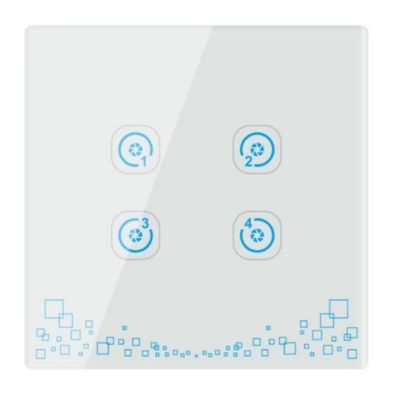
Scenario switch
CT-LCFB5055-SHB
Introduction
Feature
www.HiotH.com
Advertisement
Table of Contents

Related Manuals for HIOTH TECHNOLOGY CT-LCFB5055-SHB


Summary of Contents for HIOTH TECHNOLOGY CT-LCFB5055-SHB
- Page 1 Scenario switch CT-LCFB5055-SHB Introduction Scenario switch is a smart control panel on the basis of the traditional wall switch powered by the neutral and live wire. It can be used to link a variety of smart devices, such as appliances, lighting, etc., as well as set into several scenarios to bring your life more convenience.
- Page 2 Specification Power supply:neutral and live wire; Applicable voltage: AC 220V 50/60HZ; Static power consumption: less than 0.6W; Communication frequency: 2.4GHZ; Wireless protocol: ZigBee; Transmission maximum power: 20dB; Receiving sensitivity: < -101dBm; Operating temperature: -10 ~ 60 ℃ Operating humidity: ≤80% Installation Instruction Scenario Switch Installation CAUTION:...
- Page 3 3) Follow the Fig.2 “Wiring diagram” to start wire: Fig.2 NOTES FOR THE DIAGRAM: L - Terminal for 220V live lead N - Terminal for 220V neutral lead INSTALL THE SWITCH BASE As shown in Fig.3, install the touch switch inside the wall box after wiring, then screw up to make it fixed on the wall.
- Page 4 Using Instruction As shown in fig. 4, there is a RESET button and a Network Status Indicated LED on the panel. Network Status RESET Indicated LED Fig.4 NETWORK ENTRY 1) Connect the power supply; 2) Long press the Reset button for 5 seconds. When the network status indicated LED on (red) indicates that the device enters the network mode;...
- Page 5 Safety Notice The device requires the latest software; otherwise the status may not be accurate. A qualified electrician with the understanding of wiring diagrams and knowledge of electrical safety should complete installation following the instructions. Before installation, please confirm the real voltage complying with the device’s specification. Cut off any power supply to secure the safety of people and device.
Need help?
Do you have a question about the CT-LCFB5055-SHB and is the answer not in the manual?
Questions and answers