Table of Contents
Advertisement
Quick Links
Connecting line
NEBC-M12G5-ES-...-LE5-CO
Instructions | Assembly
8081599
2017-11
[8081601]
Translation of the original instructions
CANopen
®
, DeviceNet
®
are registered trademarks of the respective trademark
owners in certain countries.
1
Further applicable documents
All available documents for the product è www.festo.com/pk.
2
Safety
2.1
Safety instructions
–
Do not connect or disconnect plug connector when powered.
–
Before starting mounting work: Switch off power supply.
–
Observe tightening torques.
2.2
Intended use
Connecting cable with connection technology M12x1, A-coded to EN 61076-2-101
for CANopen and DeviceNet.
3
Configuration
3.1
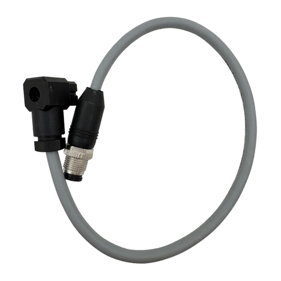
Product design
Fig. 1
3.2
Pin allocation
Port 1
Pin
1
2
3
4
5
1) Colour code in accordance with IEC 60757:1983-01
Tab. 1 Pin allocation
4
Mounting
4.1
Mounting, field device side
1. Connect socket 1 to the matching plug connector.
2. Tighten the screw-type lock of the socket 1.
4.2
Mounting, controller side
1. Shorten and pre-assemble wire ends as needed.
2. Connect the wires in accordance with the pin allocation.
4.3
Installation
Mounting in energy chain
1. Lay the chain out lengthwise.
2. Place the cables in the chain, making sure they are not twisted.
3. Separate cables from each other using separators/drill holes.
4. Do not connect cables together.
Festo SE & Co. KG
Ruiter Straße 82
73734 Esslingen
Germany
+49 711 347-0
www.festo.com
8081599
1 Socket (1x)
2 Wire end (5x)
3 Cable (1x)
Wire colour
Function
1)
–
Screening
RD
V+
BK
V–
WH
CAN_H
BU
CAN_L
Fig. 2
5. Maintain space X. X > 10 % of the cable diameter D.
If the chain is suspended vertically, increase the space X.
Fig. 3
6. Align chain in the operating position:
–
Make sure that the radius is greater than the bending radius R of the
cables.
–
Cables can move freely in the bending radius KR of the energy chain.
Ä Cables are not forced through the chain.
7. Mount chain (è corresponding assembly instructions).
8. Fasten cables:
–
At both ends of the chain in case of short energy chains (è Fig.4).
–
Only at the driver end in the case of long, sliding energy chains (è Fig.5).
Fig. 4
Fig. 5
9. Do not bend cables all the way to the fastening point.
Ä Mounting space A between the fastening point and bending movement is
observed.
NOTICE!
Damage to cables if the chain breaks.
•
Replace cables after a chain break.
NOTICE!
Malfunction and material damage due to vertically suspended cables.
The cables stretch.
•
Regularly check the length of the cables.
•
Readjust the cables if required.
5
Technical data
NEBC-M12G5-ES-...-LE5-CO
Cable characteristic
Cable composition
Shielding
Cable diameter
Suitable for energy chains
[mm²]
(2x0.34) + (2x0.25) + 0.34
Shielded
D
[mm]
6.7
Advertisement
Table of Contents

Related Manuals for Festo NEBC-M12G5-ES LE5-CO Series


Summary of Contents for Festo NEBC-M12G5-ES LE5-CO Series
- Page 1 6. Align chain in the operating position: Further applicable documents – Make sure that the radius is greater than the bending radius R of the All available documents for the product è www.festo.com/pk. cables. – Cables can move freely in the bending radius KR of the energy chain.
- Page 2 NEBC-M12G5-ES-...-LE5-CO Current rating at 40 °C Surge resistance [kV] Degree of protection IP65, IP67 Note on degree of protection In assembled state Operating voltage range 0 … 30 Bending radius Fixed cable installation [mm] ³ 35 Flexible cable installation [mm] ³ 70 Ambient temperature Fixed cable installation [°C] –25 … +80 Flexible cable installation...
Need help?
Do you have a question about the NEBC-M12G5-ES LE5-CO Series and is the answer not in the manual?
Questions and answers