Advertisement
Quick Links
Advertisement

Subscribe to Our Youtube Channel
Related Manuals for Mitsubishi Electric Mr. Slim PCA-M KA Series


Summary of Contents for Mitsubishi Electric Mr. Slim PCA-M KA Series
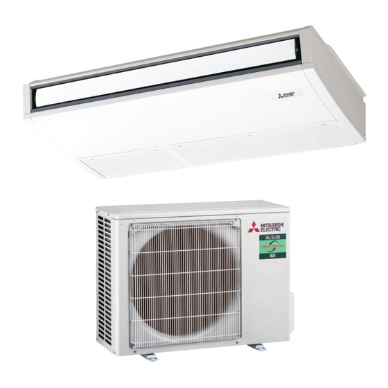
- Page 1 Packaged Air Conditioners PCA-M·KA English INSTALLATION MANUAL FOR INSTALLER...
-
Page 2: Table Of Contents
• The unit must be securely installed on a structure that can sustain its weight. • Use only accessories authorized by Mitsubishi Electric and ask a dealer or • The appliance shall be stored in a well-ventilated area where the room size an authorized technician to install them. -
Page 3: Installation Location
1. Safety precautions 1.1. Beore installation (Environment) Caution: • Do not use the unit in an unusual environment. I the air conditioner is installed • When the room humidity exceeds 80% or when the drainpipe is clogged, in areas exposed to steam, volatile oil (including machine oil), or suluric gas, water may drip from the indoor unit. -
Page 4: Installing The Indoor Unit
3. Installing the indoor unit 3.1. Check the indoor unit accessories (Fig. 3-1) The indoor unit should be supplied with the following accessories (contained in the inside o the intake grille). Accessory name Q’ty Washer 4 pcs Pipe cover 1 pc Large size (For gas tubing) Pipe cover 1 pc Small size (For liquid tubing) Band... - Page 5 3. Installing the indoor unit 3.2.3. Selection o suspension bolts and tubing positions (Fig. 3-3) Using the pattern paper provided for installation, select proper positions for suspen- sion bolts and tubing and prepare relative holes. A Pattern paper B Suspension bolt hole C Indoor unit width ø65 ø100...
-
Page 6: Installing The Refrigerant Piping
4. Installing the refrigerant piping 4.1. Precautions For devices that use R32/R410A rerigerant 45 2 • Use ester oil, ether oil or alkylbenzene oil (small amount) as the rerigeration oil applied to the fared sections. • Use C1220 copper phosphorus or copper and copper alloy seamless pipes, to connect the rerigerant pipes. -
Page 7: Drainage Piping Work
5. Drainage piping work • For let side tubing, be sure to insert the rubber plug into the right drain port. (Fig. 5-1) • Use VP-20 (O.D. ø26 (1”) PVC TUBE) or drain piping and provide 1/100 or more downward slope. •... - Page 8 6. Electrical work 6.1.1. Indoor unit power supplied rom outdoor unit The following connection patterns are available. 1 System The outdoor unit power supply patterns vary on models. 1:1 System A Outdoor unit power supply B Earth leakage breaker C Wiring circuit breaker or isolating switch D Outdoor unit E Indoor unit/outdoor unit connecting cables F Remote controller...
- Page 9 6. Electrical work Simultaneous twin/triple/quadruple system * The indoor power supply terminal kits are required. A Outdoor unit power supply B Earth leakage breaker C Wiring circuit breaker or isolating switch D Outdoor unit E Indoor unit/outdoor unit connecting cables F Remote controller G Indoor unit H Option...
- Page 10 6. Electrical work 6.2. Remote controller 6.2.1. For wired remote controller 1) 2 remote controllers setting If 2 remote controllers are connected, set one to “Main” and the other to “Sub”. For setting procedures, refer to “Function selection of remote controller” in the operation manual for the indoor unit.
- Page 11 6. Electrical work 6.3. Function settings Service menu Function setting 6.3.1. Function setting on the unit (Selecting the unit unctions) Test run Ref. address Input maintenance info. Unit No. Grp./1/2/3/4/All 1) For wired remote controller Function setting 1 (Fig. 6-5) Check Self check •...
- Page 12 6. Electrical work 2) For wireless remote controller (Fig. 6-10) Changing the power voltage setting CHECK CHECK • Be sure to change the power voltage setting depending on the voltage used. 1 Going to the function select mode CHECK Press the CHECK button F twice continuously.
-
Page 13: Test Run
7. Test run 7.1. Beore test run ► Ater completing installation and the wiring and piping o the indoor and ► Do not carry out this test on the control wiring (low voltage circuit) terminals. outdoor units, check or rerigerant leakage, looseness in the power supply Warning: or control wiring, wrong polarity, and no disconnection of one phase in the Do not use the air conditioner if the insulation resistance is less than 1 M . - Page 14 7. Test run Step 5 Stop the test run. 1 Press the [ON/OFF] button to stop the test run. (The Test run menu will appear.) Note: If an error is displayed on the remote controller, see the table below. Description of malfunction Description of malfunction Description of malfunction Intake sensor error...
- Page 15 7. Test run • Reer to the ollowing tables or details on the check codes. (Wireless remote controller) [Output pattern A] Beeper sounds Beep Beep Beep Beep Beep Beep Beep OPERATION · · · Repeated INDICATOR lamp blinking pattern Approx. 2.5 sec. 0.5 sec.
- Page 16 7. Test run [Output pattern B] Errors detected by unit other than indoor unit (outdoor unit, etc.) Wired remote Wireless remote controller controller Symptom Remark Beeper sounds/OPERATION INDICATOR lamp blinks Check code (Number o times) Indoor/outdoor unit communication error (Transmitting error) (Outdoor unit) Compressor overcurrent interruption U3, U4 Open/short of outdoor unit thermistors...
-
Page 17: Easy Maintenance Function
8. Easy maintenance unction Maintenance data, such as the indoor/outdoor unit’s heat exchanger temperature and compressor operation current can be displayed with “Smooth maintenance”. * This cannot be executed during test operation. * Depending on the combination with the outdoor unit, this may not be supported by some models. •... - Page 18 Travellers Lane, Hatfeld, Herts., AL10 8XB, England, U.K. Polish Branch Krakowska 50, PL-32-083 Balice, Poland MITSUBISHI ELECTRIC TURKEY ELEKTRİK ÜRÜNLERI A.Ş. Şeriali Mah. Kale Sok. No: 41 34775 Ümraniye, İstanbul / Turkey Please be sure to put the contact address/telephone number on this manual beore handing it to the customer.
Need help?
Do you have a question about the Mr. Slim PCA-M KA Series and is the answer not in the manual?
Questions and answers