Table of Contents
Advertisement
Quick Links
Advertisement
Table of Contents

Related Manuals for Cardinal CLiC WD-02.1.4

Summary of Contents for Cardinal CLiC WD-02.1.4
- Page 1 CARDINAL CLiC WD-02.1.4 GLASS CONTROLLER INSTALLATION MANUAL Rev. A...
-
Page 2: Important Safety Instructions
PRECAUTIONS IMPORTANT SAFETY INSTRUCTIONS Read Instructions: Read all safety and operating instructions before using the device. Retain Instructions: Keep safety and operating instructions for future reference. Heed Warnings: Adhere to all warnings on the device and in the operating instructions. Follow Instructions: Follow operating instructions and installation instructions. Failure to follow these instructions may damage the product or void the product warranty. Heat: Keep the device away from heat sources such as radiators, heat registers, stoves, etc. Power Sources: Connect only to the Class 2 power supply that was included with the device. Power Cord Protection: Route power supply cords so that they are not likely to be stepped on or pinched by items placed on or against them. Paying particular attention to the cords at plugs, receptacles, and at the point at which they connect to the device. Water and Moisture: Do not use the device near water; for example, near a sink, in a wet basement, near a swimming pool, near an open window, in a damp mechanical room, etc. Object and Liquid Entry: Do not allow objects to fall or liquids to be spilled into the enclosure through openings. Indoor Use Only: The device should be installed and used indoors only. Do not use the device outdoors. Servicing: There are no user serviceable parts inside of the device. Do not attempt to open the enclosure or perform any service beyond that described in the operating instructions. Refer all other service needs to qualified service personnel. CLiC Glass Wiring: Controller only detects shorts upon glass transition, will not protect against a short that occurs while in the clear state ... -
Page 3: Fcc Information To Users
DISCLAIMER FCC INFORMATION TO USERS FCC Information to Users This equipment has been tested and found to comply with the limits for a Class B digital device, pursuant to Part 15 Subpart B of the FCC Rules. These limits are designed to provide reasonable protection against harmful interference in commercial, industrial, and residential installations. This equipment generates, and can radiate radio frequency energy and, if not installed and used in accordance with the instruction manual, may cause harmful interference to radio communications. However, there is no guarantee that interference will not occur in a particular installation. If this equipment does cause harmful interference to radio or television reception, which can be determined by turning the equipment off and on, the user is encouraged to try to correct the interference by one or more of the following measures: Reorient or relocate the receiving antenna Increase the separation between the equipment and receiver Connect the equipment into an outlet on a circuit different from that to which the receiver is connected Consult the dealer or an experienced radio/TV technician for help Warning: Changes or modifications not expressly approved by Cardinal IG Company could void the user’s authority to operate the equipment. Page 3 of 14 Rev. A... -
Page 4: Table Of Contents
CONTENTS TABLE OF CONTENTS Important Safety Instructions .......................... 2 FCC Information to Users ........................... 3 Overview ................................ 5 Important Notes .............................. 5 Compatibility .............................. 5 What’s In The Box? ............................ 5 Unpacking and Inspection .......................... 6 Controller Layout ............................... 6 Mounting ................................ 7 Power ................................ 7 Wire Connection Terminals .......................... 8 LED Operating Modes ............................ 8 Site Wiring and Preparation .......................... 9 System Layout Examples ........................... 1 1 Specifications .............................. 1 2 ... -
Page 5: Overview
CHAPTER 1 - INTRODUCTION OVERVIEW This guide pertains to the Cardinal CLiC WD‐02.1.4 Glass Controller. This device and the associated CLiC Glass Panel have been designed as a Class‐3 system. The purpose of this document is to provide guidance on how to setup and install the device into a commercial, industrial, or residential environment. This document includes installation site requirements, wiring requirements, system connection instructions, and basic troubleshooting. IMPORTANT NOTES Please read these important notes about the CLiC WD‐02.1.4 Glass Controller: The WD‐02.1.4 must be installed within a dry, ventilated area that maintains a normal room temperature (between 10°C to 40°C). Avoid installing the WD‐02.1.4 in a location where it will have exposure to prolonged direct sunlight. Do not let the WD‐02.1.4 get wet. It should not be handled with wet hands or placed in an area where it could get wet. Installer shall use the provided UL Listed Class 2 power supply with a 24 Vdc power output for connection to this controller. All wiring and installation shall be in accordance with the NEC. Using the wrong type of power supply may result in damage. Do not disassemble the device. Service of the WD‐02.1.4 should be performed by authorized personnel only. COMPATIBILITY This device is specifically designed for use only with CLiC Glass panels. Use this device only for its intended use as described in these instructions. Do not use attachments not recommended by the manufacturer. Connecting this device to load types other than CLiC Glass panels may damage the device or the unauthorized loads. Cardinal IG Company will not be responsible for any damage caused by inappropriate usage of this device. WHAT’S IN THE BOX? The following items are included with the CLiC WD‐02.1.4 Glass Controller: Quick Start Guide Power Supply: 24v DC 100‐watt UL‐1310 Class‐2 With 2‐pin screw terminal connector (male) pre‐connected Rubber Feet ... -
Page 6: Unpacking And Inspection
UNPACKING AND INSPECTION After opening the WD‐02.1.4 package, save all the packaging material in case you ever need to ship the unit. Thoroughly inspect and make sure the devices are in good condition and there is no visible damage. If you have any doubt about the product’s integrity, please contact your reseller or an authorized support center immediately. CHAPTER 2 - FEATURES CONTROLLER LAYOUT Page 6 of 14 Rev. A... -
Page 7: Mounting
CHAPTER 3 – INSTALLATION MOUNTING The CLiC WD‐02.1.4 Glass Controller can be mounted within an enclosure or free standing. The WD‐02.1.4 does not need to be mounted near the CLiC Glass panel. The CLiC Glass output and the dry contact input can be extended up to 100 meters (328 feet). Mounting Pattern Drawings POWER ! O NOT APPLY POWER PRIOR TO COMPLETING ALL WIRING CONNECTIONS AND TERMINATIONS CLiC LL PROTECTIVE FILMS MUST BE REMOVED FROM THE GLASS PANEL PRIOR TO CONNECTING THE WD‐ 02.1.4 GLASS CONTROLLER The included power supply (A/C Adapter) should be connected to the ‘24 VDC in’ and ‘Ground’ input terminals on the WD‐02.1.4. The terminal connector will be pre‐attached to the power supply. The CLiC WD‐02.1.4 will power on and begin functioning upon applying power. Use the provided UL Listed Class 2 power supply with a 24 VDC power output for connection to this control. All wiring and installation shall be in accordance with the NEC. Do not connect more than one WD‐02.1.4 to a power supply. Page 7 of 14 Rev. A... -
Page 8: Wire Connection Terminals
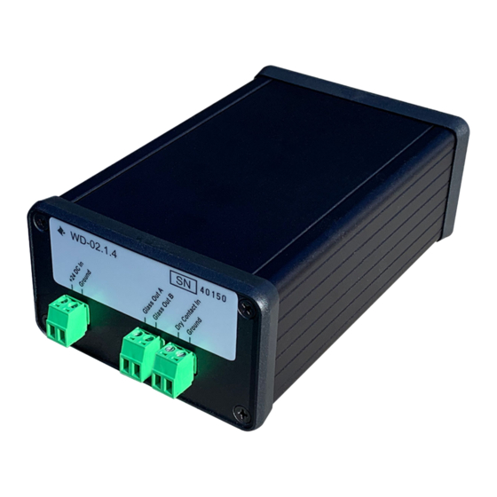
WIRE CONNECTION TERMINALS Terminal: +24 DC In Positive 24‐volt DC power supply connection. This is to power the device. Terminal: Ground Common ground connection. Use this ground reference for power supply ground connection. Terminal: Glass Out A This is the signal output used for controlling the CLiC Glass panel. Both Glass Out A and Glass Out B must be connected to the CLiC Glass panel. Glass Out A and Glass Out B must each connect to a single CLiC glass panel. There is no polarity on these connections. Shorting the outputs while powered could damage the WD‐02.1.4 and should be avoided. : Only connect a single CLiC Glass panel. Multiple controllers must be used for multiple CLiC Glass panels. Terminal: Glass Out B This is the signal output used for controlling the CLiC Glass panel. Both Glass Out A and Glass Out B must be connected to the CLiC Glass panel. Glass Out A and Glass Out B must each connect to a single CLiC glass panel. There is no polarity on these connections. Shorting the outputs while powered could damage the WD‐02.1.4 and should be avoided. : Only connect a single CLiC Glass panel. Multiple controllers must be used for multiple CLiC Glass panels. Terminal: Dry Contact In The WD‐02.1.4 has a dry contact input that is used to allow external devices to control the state of the CLiC Glass panel. The triggering device shall use a ground referenced switch or relay type output. The CLiC Glass panel will go to the clear state when the contact closure is closed. The CLiC Glass panel will go to the private state when the contact closure is open. Terminal: Ground Common ground connection. Use this ground reference for dry contact ground connections. LED OPERATING MODES The LEDs are included to indicate the status of the CLiC controller. The behavior of the LEDs will change under different operating conditions. The following table details that behavior: Blue LED Green LED Description Off Off No power to the unit ... -
Page 9: Site Wiring And Preparation
INSTALLATION AND OPERATION SITE WIRING AND PREPARATION Wiring from the WD‐02.1.4 to the CLiC Glass panel should be run prior to the CLiC Glass panel installation. All wiring must be performed in accordance with the applicable building codes and electrical wiring requirements as denoted for Class 3 systems of the National Electric Code (NEC). All wiring should be completed by a qualified and experienced technician. Placement The WD‐02.1.4 should be installed within an accessible area with adequate proximity to plug the power supply into a standard 120vac outlet. The included power supply is mountable if desired. Please allow adequate space for ventilation and heat dissipation around the devices. : N THE EVENT THAT THESE DEVICES ARE USED IN A ‐... - Page 10 IMPORTANT: EMOVAL OF PROTECTIVE FILMS CAN PRODUCE ELECTRIC SHOCKS AND SPARKS WHICH COULD CAUSE ! DAMAGE TO CONNECTED ELECTRONICS PRIOR ! LL PROTECTIVE FILMS MUST BE REMOVED TO CONNECTION OF THE GLASS CONTROLLER WD‐02.1.4 Dry Contact Connections The WD‐02.1.4 has been designed to accommodate many installation configurations and scenarios by utilizing a flexible Dry Contact Input Circuit. This circuit allows a wide variety of switch devices, relays, or other automation controllers to provide end user control of the CLiC Glass panel. The triggering device shall use a ground referenced switch or relay type output. There shall be no power applied directly to the Dry Contact connections. These devices can include, but are not limited to: Standard light switches U ‐...
-
Page 11: System Layout Examples
SYSTEM LAYOUT EXAMPLES Please review the following diagrams for example wiring scenarios: Single Channel Multiple Channels Multiple Individual Switches Multiple Channels Single Switch Multiple Channels with Automation and Relay Controls Page 11 of 14 Rev. A... -
Page 12: Specifications
SPECIFICATIONS Power Supply Requirements 24VDC 100‐Watt UL1310 Class 2 Power Limited CLiC Control Output 100VA Max, Capacitive Load, Class 3 AC Voltage Power Output Circuit Note that the output of this controller is considered a power limited circuit, Class 3 circuit, in accordance with Article 725 of the National Electrical Code NFPA 70. Input Trigger Type Open Collector; Shunt to Ground WD‐02.1.4 Dimensions (W x H x D) without feet 3.19” x 4.96” x 1.81” Included Power Supply Dimensions (W x H x D) 8.75” x 2.68” x 1.53” (222.2mm x 68mm x 38.8mm) Weight (without included power supply) 8.92 oz (0.56 lbs.) Weight (with included power supply) 52.44 oz (3.28 lbs.) Operating Temperatures 50°F to 104°F (10°C to 40°C) Storage and Transportation ‐40°F to 140°F (‐40°C to 60°C) Certifications NEC Class 3, FCC Part 15 Subpart B Class B Purpose of Control Operating Control, Electronic Window Controller Construction of Control Independently Mounted Pollution Degree 2 Rated Impulse Voltage 330V Overvoltage Category I Protection Against Electric Shock Class II ... -
Page 13: Common Symptoms And Solutions
TROUBLESHOOTING COMMON SYMPTOMS AND SOLUTIONS If you are experiencing problems with your WD‐02.1.4 or CLiC Glass panel, please read the information below before contacting technical support. If you continue to experience problems, see the next chapter for more information on contacting Cardinal IG Company technical support. Symptom Troubleshooting Steps 1. Verify wiring from switch or dry contact device to Glass Controller Glass stuck in Clear State 2. Verify switch or dry contact device is functioning properly and opening (It will not change state) the circuit 1. Verify wiring from Glass Controller to the CLiC Glass panel 2. Verify wiring from switch or dry contact device to Glass Controller 3. Verify switch or dry contact device is functioning properly and closing the circuit Glass stuck in Private State 4. If controller is flashing green when activating the dry contact, the (It will not change state) controller is detecting either a short circuit or an open circuit in the Glass Out line. 5. Verify presence of 24VDC at terminal on Glass Controller 6. See No Power to Glass Controller Below 1. Verify the power supply is plugged into a wall outlet 2. Verify that the wall outlet has power 3. Verify the wiring from the power supply to the Glass Controller and No power at Glass Controller that the connector is fully inserted 4. Thermal protection may have been activated on the power supply. ... -
Page 14: Contacting
SERVICE AND SUPPORT CONTACTING US Contacting Cardinal IG Company For general information, you can contact Cardinal IG Company at: Cardinal IG Company 7201 W Lake St Minneapolis, MN 55426 (952) 314‐4757 Contacting Technical Support At Cardinal IG Company, customer service and satisfaction are two of our core missions. If you are experiencing any problems or have a question regarding your CLiC products, please contact our technical support department by email at: CLiCsupport@cardinalcorp.com Please include the following information within your email: Your Name Company Name Telephone Number Email address Product models and serial numbers Detailed description of your question or the problems you are experiencing We greatly appreciate your purchase of Cardinal CLiC products, and we strive to provide a long lasting and trouble‐ free customer experience. Our goal is to respond to your email in a timely manner and to expediently resolve any issues you are experiencing. Visit our Website for the Latest Information You can find the latest revision of this manual, as well as, a list of frequently asked questions, and an easy way to contact us. www.clicglass.com Page 14 of 14...
Need help?
Do you have a question about the CLiC WD-02.1.4 and is the answer not in the manual?
Questions and answers