
Related Manuals for Eaton STS 2000A


Summary of Contents for Eaton STS 2000A
- Page 1 Eaton © Static Transfer Switch 2000A 3-Pole Installation and Operation Manual p/n: 164001127 Revision 01...
- Page 2 PDI, JCOMM, Quad-Wye, ToughRail Technology, and WaveStar are registered trademarks of Power Distribution Inc. All other trademarks are property of their respective companies. ©Copyright 2023 Eaton, Raleigh, NC, USA. All rights reserved. No part of this document may be reproduced in any way without the express written approval of Eaton.
- Page 3 Dear Customer, On behalf of everyone at Eaton, we thank you for partnering with us, and trusting us to maintain your business continuity and preventing downtime at your facility. Our suite of backup power, power distribution and power management products are designed to protect you from a host of threats including power outages, surges, lighting strikes, and enable you to monitor and control your power infrastructure.
- Page 4 Licensee or other subsidiary of Licensee’s parent, to copy, distribute, or otherwise transfer the Firmware without the prior written consent of Eaton. Licensee may transfer the Firmware directly to a third party only in connection with the sale of the Eaton product in which it is installed.
- Page 5 TO THE EXTENT PERMITTED BY APPLICABLE LAW, THE USE OF THE PRODUCT IS AT LICENSEE’S SOLE RISK. 5.0 GENERAL PROVISIONS 5.1 Update Policy. Eaton may from time to time, but has no obligation to, create Updates of the Firmware or components thereof. 5.2 Limitation on Liability. NOTWITHSTANDING ANY PROVISION OF THIS AGREEMENT TO THE...
- Page 6 Firmware pursuant to license arrangements between Eaton and such third parties. Third Party Licensor components in the Firmware are not licensed or warranted under the terms of this document, but are instead subject to the Third Party Licensors’...
- Page 7 Eaton, the disclosure of which would cause substantial harm to Eaton that could not be remedied by the payment of damages alone and such confidential aspects of the Firmware shall not be disclosed to third parties without the prior written consent of Eaton.
- Page 9 3.8.1 Circuit Breaker Rating and Upstream Protection ..................19 3.8.2 Optional Isolation MCSW ........................19 3.8.3 Power Sources........................... 19 3.8.4 Customer Power Connections ....................... 19 3.8.5 Control Wiring............................ 20 3.9 Class A Computing Device ......................... 20 Eaton Static Transfer Switch 2000A 3-Pole Installation and Operation Manual 164001127—Rev 01...
- Page 10 8 8 O O p p e e r r a a t t i i o o n n a a l l M M o o d d e e s s ......................................................4 4 1 1 8.1 Normal Mode Operation..........................41 8.1.1 Preferred Source ..........................41 8.1.2 Retransfer Control..........................41 8.1.3 Manual Transfers..........................42 Eaton Static Transfer Switch 2000A 3-Pole Installation and Operation Manual 164001127—Rev 01...
- Page 11 12.2.4 Downloading the Event Log File ......................69 12.2.5 Plots Screen ............................ 69 12.3 Additional Status Screens ......................... 71 12.3.1 Harmonics Screen..........................71 12.3.2 Load Screen............................. 71 12.3.3 Branch Screen..........................72 Eaton Static Transfer Switch 2000A 3-Pole Installation and Operation Manual 164001127—Rev 01...
- Page 12 1 1 7 7 S S e e r r v v i i c c e e ............................................................1 1 0 0 3 3 17.1 The Service Promise..........................103 17.2 Preventive Maintenance......................... 103 17.3 Eaton Provides Flexibility and Commitment ....................103 17.4 Time and Materials..........................103 Eaton Static Transfer Switch 2000A 3-Pole Installation and Operation Manual 164001127—Rev 01...
- Page 13 STS Web Server Home Page ......................75 Figure 37. Analog Web Page......................... 76 Figure 38. One-Line Web Page........................77 Figure 39. Event Log Download to Spreadsheet....................77 Eaton Static Transfer Switch 2000A 3-Pole Installation and Operation Manual 164001127—Rev 01 xiii...
- Page 14 List of Figures Figure 40. Waveforms Web Page ........................78 Eaton Static Transfer Switch 2000A 3-Pole Installation and Operation Manual 164001127—Rev 01...
- Page 15 KVA Alarms Default Settings 600V Unit .................... 102 Table 11. KVA Alarms Default Settings 480V Unit .................... 102 Table 12. KVA Alarms Default Settings 208V Unit .................... 102 Eaton Static Transfer Switch 2000A 3-Pole Installation and Operation Manual 164001127—Rev 01...
- Page 16 List of Tables Eaton Static Transfer Switch 2000A 3-Pole Installation and Operation Manual 164001127—Rev 01...
- Page 17 Circuit breaker nuisance tripping Transfer Switch The STS 2000A is a standalone transfer switch with two AC input sources and one AC output load. The STS transparently transfers the output load automatically from one power source to the other, if the active source fails or goes out of specification, or manually by operator directive, for testing or maintenance.
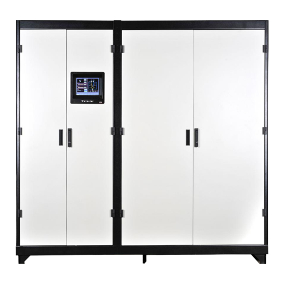
- Page 18 System Description Figure 1. STS 2000A 3-pole, General Assembly Drawing Eaton Static Transfer Switch 2000A 3-Pole Installation and Operation Manual 164001127—Rev 01...
- Page 19 Figure 2. STS 2000A Front View, Panels Off Source 1 MCCB Logic/PCB Compartment Source 2 MCCB Display Bypass 1 MCCB Redundant Operator Bypass 2 MCCB Interface (ROI) Compartment Isolation 1 MCCB Isolation 2 MCCB (optional) Eaton Static Transfer Switch 2000A 3-Pole Installation and Operation Manual 164001127—Rev 01...
- Page 20 Figure 4. The one-line diagram shows active and inactive power paths and other status. Redundant Operator Interface (ROI) (shown with panel open) backs up display and monitor logic. Eaton Static Transfer Switch 2000A 3-Pole Installation and Operation Manual 164001127—Rev 01...
- Page 21 System Description Figure 4. STS 2000A Rear View, Panels Off Cable Entry/Exit Source 2 Bus Source 1 Bus Connections Connections Output Bus Connections Cable Entry/Exit Eaton Static Transfer Switch 2000A 3-Pole Installation and Operation Manual 164001127—Rev 01...
- Page 22 1 1 . . 3 3 . . 2 2 S S e e n n s s e e a a n n d d T T r r a a n n s s f f e e r r A A l l g g o o r r i i t t h h m m s s Sense algorithms detect that the active power source is going out of specification and that a transfer is required. Eaton PDI has optimized STS sense algorithms experimentally, but algorithm parameters can be adjusted by administrators if necessary.
- Page 23 – Manual transfers are ≤ 1/8 cycle for in-phase conditions. The STS 2000A can successfully switch the load between sources that are 180⁰ out-of-phase within the above- specified cycle times. VSS is the recommended and default algorithm and should be used whenever there are transformers downstream of the STS, including small transformers embedded in devices.
- Page 24 POG or VSS algorithm, as specified by the user. The Monitor is itself continuously monitored by the Simple Algorithm Switch (SAS), which provides a backup transfer process using a simpler algorithm, if the Monitor fails. Eaton Static Transfer Switch 2000A 3-Pole Installation and Operation Manual 164001127—Rev 01...
- Page 25 H H i i g g h h A A v v a a i i l l a a b b i i l l i i t t y y t t h h r r o o u u g g h h R R e e d d u u n n d d a a n n c c y y To keep a mission-critical load continuously supplied with power, the STS must itself be continuously operational. To the fullest extent practical, the STS 2000A employs redundant circuits and components to eliminate single points of failure.
- Page 26 S S y y s s t t e e m m S S e e c c u u r r i i t t y y The STS 2000A is designed for mission-critical environments and has security features appropriate to that environment: •...
- Page 27 C C o o m m m m u u n n i i c c a a t t i i o o n n s s The STS 2000A can transmit alarms, status, and waveform data to remote locations and receive control signals using several communications methodologies: •...
- Page 28 1 1 . . 1 1 4 4 G G e e t t t t i i n n g g H H e e l l p p If help is needed with any of the following: • Scheduling initial startup • Regional locations and telephone numbers Eaton Static Transfer Switch 2000A 3-Pole Installation and Operation Manual 164001127—Rev 01...
- Page 29 1 1 . . 1 1 5 5 W W a a r r r r a a n n t t y y To view the warranty please click on the link or copy the address to download from the Eaton website: UPS Product Warranty https://www.eaton.com/content/dam/eaton/products/backup-power-ups-surge-it-power-distribution/backup-...
- Page 30 System Description Eaton Static Transfer Switch 2000A 3-Pole Installation and Operation Manual 164001127—Rev 01...
- Page 31 Install equipment in an appropriate electrical environment per local regulations. • ESD sensitive equipment. Ground yourself, discharge any static charge and ensure that the device is effectively grounded before handling the unit. Eaton Static Transfer Switch 2000A 3-Pole Installation and Operation Manual 164001127—Rev 01...
- Page 32 Safety Eaton Static Transfer Switch 2000A 3-Pole Installation and Operation Manual 164001127—Rev 01...
- Page 33 S S y y s s t t e e m m E E n n c c l l o o s s u u r r e e The STS 2000A enclosure is designed for the data center or telecommunications environment. The enclosure is...
- Page 34 Electromagnetic fields from portable transmitters within 3 feet (1 meter) of the unit Grounding for the WaveStar Static Transfer Switch must comply with local building codes and National Electric Codes. Eaton Static Transfer Switch 2000A 3-Pole Installation and Operation Manual 164001127—Rev 01...
- Page 35 3 3 . . 8 8 . . 1 1 C C i i r r c c u u i i t t B B r r e e a a k k e e r r R R a a t t i i n n g g a a n n d d U U p p s s t t r r e e a a m m P P r r o o t t e e c c t t i i o o n n The STS 2000A has input source and bypass MCCBs that are 100 percent rated for 2000A, the full load rating of the unit.
- Page 36 Operation of this equipment in a residential area is likely to cause interference in which case the user at his/her own expense will be required to take whatever measures may be required to correct the interference. Eaton Static Transfer Switch 2000A 3-Pole Installation and Operation Manual 164001127—Rev 01...
- Page 37 Installation Planning Figure 9. General Assembly Drawing: Customer Power Connections Eaton Static Transfer Switch 2000A 3-Pole Installation and Operation Manual 164001127—Rev 01...
- Page 38 Installation Planning Eaton Static Transfer Switch 2000A 3-Pole Installation and Operation Manual 164001127—Rev 01...
- Page 39 U U n n l l o o a a d d i i n n g g , , U U n n p p a a c c k k i i n n g g , , a a n n d d H H a a n n d d l l i i n n g g You should unpack your Eaton PDI product with the same care used in packing the product for safe and efficient delivery to your facility.
- Page 40 The Installer should review the STS for connections and safety prior to final positioning and installation. If any loose connections are found during the installation, contact Eaton Service (1-800-843-9433). Check these connections to make sure vibration has not loosened the terminal screws.
- Page 41 1996 National Electric Code for access to Circuit Breaker distribution equipment. Check STS floor loading to verify that the STS 2000A system does not exceed the raised floor loading specifications. System weight and cabinet dimensions are given in 3.1 System...
- Page 42 5 5 . . 1 1 . . 3 3 C C o o m m m m i i s s s s i i o o n n i i n n g g : : I I n n i i t t i i a a l l P P o o w w e e r r - - u u p p S S i i t t e e T T e e s s t t An Eaton certified technician must commission and perform acceptance testing on the STS 2000A unit to initiate warranty coverage. All the work performed in this section must be performed or witnessed by an Eaton Service Representative.
- Page 43 Chapter 9 System Setup: Administration. • Operational setup: configure transfer parameters. See Chapter 10 System Setup: Operation. • Network setup: configure networking options and addresses. See Chapter 11 System Setup: Networking. Eaton Static Transfer Switch 2000A 3-Pole Installation and Operation Manual 164001127—Rev 01...
- Page 44 Installation and Startup Procedures Eaton Static Transfer Switch 2000A 3-Pole Installation and Operation Manual 164001127—Rev 01...
- Page 45 For making or changing connections, access the Contractor Board through its own front panel door. The following sections describe the formats of the Basic and Enhanced Contractor Boards. Eaton Static Transfer Switch 2000A 3-Pole Installation and Operation Manual 164001127—Rev 01...
- Page 46 Connection of voltage to this point can cause damage to the unit. Connect external dry contacts to terminals marked +24v and EPO for EPO circuit. The return position enables a light for the remote EPO button. Eaton Static Transfer Switch 2000A 3-Pole Installation and Operation Manual 164001127—Rev 01...
- Page 47 Remote relays can accept dry contacts rated up to 2A/250V. The Contractor Boards have multiple applications in Eaton PDI products and not all connections are supported on the STS 2000A. The following connections are not currently supported on this product: •...
- Page 48 The name of the Building Alarm is specified in the points list. A building alarm causes a point to be activated in the points list, but causes no other action. Eaton Static Transfer Switch 2000A 3-Pole Installation and Operation Manual 164001127—Rev 01...
- Page 49 An “Inhibit Transfer” alarm is signaled on each STS. The STSs are prevented from transferring until the Preferred Source on the STS using the backup UPS returns to normal and the STS retransfers the load back to the Preferred Source. Eaton Static Transfer Switch 2000A 3-Pole Installation and Operation Manual 164001127—Rev 01...
- Page 50 Customer Communications Connections Eaton Static Transfer Switch 2000A 3-Pole Installation and Operation Manual 164001127—Rev 01...
- Page 51 Transfers panel has a counter of the number of transfers that have occurred since the last Clear of this counter. The Home screen also has Preferred Source control (see 8.1.1 Preferred Source). Eaton Static Transfer Switch 2000A 3-Pole Installation and Operation Manual 164001127—Rev 01...
- Page 52 Viewing screens does not require login, nor does viewing screens remotely using a web browser. However, to use controls or change parameters, a user must log in from the Operator panel on the Home screen and have an access level that permits the action. Eaton Static Transfer Switch 2000A 3-Pole Installation and Operation Manual 164001127—Rev 01...
- Page 53 To Log out: Touch Log In on Home screen Touch Cancel on Keyboard screen The display returns to Home screen and Operator box reads “Locked” on Home screen. Eaton Static Transfer Switch 2000A 3-Pole Installation and Operation Manual 164001127—Rev 01...
- Page 54 NOTE 2: The MAINTENANCE light on the ROI panel refers to the Maintenance Bypass, an internal switch used by service personnel to disable MCCB/MCSW trip units during maintenance. Eaton Static Transfer Switch 2000A 3-Pole Installation and Operation Manual 164001127—Rev 01...
- Page 55 Green = Source is available (within Green = powering the load (SCR on) specification). Red = not powering the load (SCR off) Red = Source is not available. Eaton Static Transfer Switch 2000A 3-Pole Installation and Operation Manual 164001127—Rev 01...
- Page 56 Operational Interfaces Eaton Static Transfer Switch 2000A 3-Pole Installation and Operation Manual 164001127—Rev 01...
- Page 57 Preferred Source takes to come back within specification—and will remain connected to the Preferred Source until it fails or a transfer is manually initiated. • Retransfer = Yes is the default setting for this control. Retransfer = No: Eaton Static Transfer Switch 2000A 3-Pole Installation and Operation Manual 164001127—Rev 01...
- Page 58 Failure of both sources. If both sources fail, the logic locks on the last available source for 100ms. After 100 ms, the logic will transfer the load to the first available source that returns to acceptable operating limits. Example A: Eaton Static Transfer Switch 2000A 3-Pole Installation and Operation Manual 164001127—Rev 01...
- Page 59 B B y y p p a a s s s s M M o o d d e e The STS has a Bypass Mode for maintenance. In Bypass Mode, all electronic components are isolated from the power sources to allow safe unit servicing. Eaton Static Transfer Switch 2000A 3-Pole Installation and Operation Manual 164001127—Rev 01...
- Page 60 (Figure 17). Engaging the bypass and returning from bypass to STS normal mode both require the operator to manipulate Kirk Keys and MCCBs or MCSWs. Eaton Static Transfer Switch 2000A 3-Pole Installation and Operation Manual 164001127—Rev 01...
- Page 61 Rotate and remove the key from the Source 2 input MCCB; insert it in the Source 1 BypassMCCB and turn the key. Verify key 3 is in Bypass 1. (If key 3 is located in Bypass 2, remove it and insert it in Bypass1.) Eaton Static Transfer Switch 2000A 3-Pole Installation and Operation Manual 164001127—Rev 01...
- Page 62 19). When the system senses a step has been completed, the Help screen proceeds to the next step. The Voice Unit also calls out each step as the operator executes the procedure. Eaton Static Transfer Switch 2000A 3-Pole Installation and Operation Manual 164001127—Rev 01...
- Page 63 The process of going to bypass will normally generate alarms, for example, change of breaker status. The Help panel indicates completion of the procedure (“In Bypass 1”). The Status panel shows “Load on Bypass!!!” Eaton Static Transfer Switch 2000A 3-Pole Installation and Operation Manual 164001127—Rev 01...
- Page 64 Operational Modes Eaton Static Transfer Switch 2000A 3-Pole Installation and Operation Manual 164001127—Rev 01...
- Page 65 Anyone can view the different display screens, but a login is required to use controls or make changes to parameters. The STS has four access levels: Eaton PDI: This level has authorization for all actions except clearing the Event Log. Eaton PDI access is required to use the Configuration screen.
- Page 66 System Setup: Administration – O: Operator • The Eaton PDI class is hard coded and cannot be assigned by the administrator. Figure 20. Users Screen User being set up is Scroll through highlighted (blinking). User List to highlight a User Name or number.
- Page 67 Use arrow keys (˂ ˃) to position cursor: entering data overwrites text at cursor position; it does not insert text. Clear button clears entire entry. Cancel button returns to Users page without changing data. Eaton Static Transfer Switch 2000A 3-Pole Installation and Operation Manual 164001127—Rev 01...
- Page 68 11. Log out as Administrator in order to test the user log in. (See 7.1.4 User/Operator Login to log out.) Only one user at a time can be logged in. Operator panel shows Locked. Eaton Static Transfer Switch 2000A 3-Pole Installation and Operation Manual 164001127—Rev 01...
- Page 69 14. Log the User out. (See 7.1.4 User/Operator Login) 15. All user log-ins and log-outs are logged. The Event Log screen shows these events for both the Administrator and the User. Eaton Static Transfer Switch 2000A 3-Pole Installation and Operation Manual 164001127—Rev 01...
- Page 70 System Setup: Administration Eaton Static Transfer Switch 2000A 3-Pole Installation and Operation Manual 164001127—Rev 01...
- Page 71 Touch the Config button to view. Eaton PDI uses the Configuration screen to describe the system to the Monitor software, which is common for all Eaton PDI STS products. Parameters include physical characteristics (standalone or redundant system, contractor board installation, fans, number of isolation MCSWs), power (voltages, frequency, KVA, etc.), and...
- Page 72 The remaining parameters are Optimization parameters for the sense, transfer, and retransfer algorithms. These parameters have been experimentally set and optimized by Eaton PDI. NOTE: Eaton PDI strongly recommends that the Fast, Delayed, and Retransfer Delay settings not be changed.
- Page 73 Retransfer Delay 0 Samples Ratchet Switching – Retransfer Switching – Slow Settings Parameter Value Parameter Value Delay 10 Seconds High Limit 110% Low Limit Delay 256 Samples Ratchet Eaton Static Transfer Switch 2000A 3-Pole Installation and Operation Manual 164001127—Rev 01...
- Page 74 System Setup: Operation Eaton Static Transfer Switch 2000A 3-Pole Installation and Operation Manual 164001127—Rev 01...
- Page 75 6.2 Ethernet Connection.) The Ethernet cable must be physically attached to the customer network and STS Ethernet addresses set before ModBus TCP/IP, SNMP, or SNTP Time Synchronization are configured. Eaton Static Transfer Switch 2000A 3-Pole Installation and Operation Manual 164001127—Rev 01...
- Page 76 GPS receiver, a local computer running time server software, or a timeserver on the Internet. You should preferably use a local time server. All equipment related to the STS should use the same time server if they have access. Eaton Static Transfer Switch 2000A 3-Pole Installation and Operation Manual 164001127—Rev 01...
- Page 77 STS. Touch the SNMP button on the Home Screen to display the SNMP Screen (Figure 25). Touch MORE to display additional buttons if SNMP button doesn’t show. Eaton Static Transfer Switch 2000A 3-Pole Installation and Operation Manual 164001127—Rev 01...
- Page 78 Touch Send SNMP Traps to toggle the between a green check mark (OK to send traps) and red X (do not send traps). The STS 2000A supports SNMP Version 1. Supported SNMP message types are Get and GetNext. The SNMP MIB is available on the Eaton PDI website.
- Page 79 27). You can connect a 9600 baud modem to the Enhanced Contractor Board. The modem can be used to send a summary alarm to one or two specified destinations. Eaton Static Transfer Switch 2000A 3-Pole Installation and Operation Manual 164001127—Rev 01...
- Page 80 To test the modem dial out feature, touch Dial 1 or Dial 2 to force the modem to dial number 1 or 2. Touch Reset to reset the modem. Eaton Static Transfer Switch 2000A 3-Pole Installation and Operation Manual 164001127—Rev 01...
- Page 81 The first column is the description of the digital point value’s alarm or abnormal state. Their dot indicator at the beginning of each row indicating the general state of point (for explanation of indicator, see Figure 28). Eaton Static Transfer Switch 2000A 3-Pole Installation and Operation Manual 164001127—Rev 01...
- Page 82 Figure 29. Analog Values Screen Each row displays an analog point with its status and last measurement. The dot indicators at the beginning of each row indicate the status of the point: Eaton Static Transfer Switch 2000A 3-Pole Installation and Operation Manual 164001127—Rev 01...
- Page 83 Modem dial out • The Alarms screen lists a new alarm. • The Event Log screen adds an alarm. • The Alarms or Log web page shows a new alarm. Eaton Static Transfer Switch 2000A 3-Pole Installation and Operation Manual 164001127—Rev 01...
- Page 84 Changes in state for digital points (binary states) in the Digital Points list (see 16.1 Digital Screen Points). • Crossed thresholds for analog points (measurements) in the Analog Points list (see 16.2 Analog Screen Points). Eaton Static Transfer Switch 2000A 3-Pole Installation and Operation Manual 164001127—Rev 01...
- Page 85 1 1 2 2 . . 2 2 . . 5 5 P P l l o o t t s s S S c c r r e e e e n n Touch the Plots button in the navigation buttons to display the Plots screen (Figure 32). Eaton Static Transfer Switch 2000A 3-Pole Installation and Operation Manual 164001127—Rev 01...
- Page 86 Phase A is blue, Phase B is red, and Phase C is black. These displays show breaks in the waves if there has been an outage or a transfer. Touch the Clear button to clear all plots. Eaton Static Transfer Switch 2000A 3-Pole Installation and Operation Manual 164001127—Rev 01...
- Page 87 1 1 2 2 . . 3 3 . . 2 2 L L o o a a d d S S c c r r e e e e n n Touching the Load button displays the Load Screen (Figure 34). Eaton Static Transfer Switch 2000A 3-Pole Installation and Operation Manual 164001127—Rev 01...
- Page 88 1 1 2 2 . . 3 3 . . 3 3 B B r r a a n n c c h h S S c c r r e e e e n n The standalone STS 2000A does not have distribution branch circuits and the Branch screen does not apply.
- Page 89 Status, Alarms, and Other Diagnostic Information Figure 35. Help Procedure Examples Eaton Static Transfer Switch 2000A 3-Pole Installation and Operation Manual 164001127—Rev 01...
- Page 90 Status, Alarms, and Other Diagnostic Information Eaton Static Transfer Switch 2000A 3-Pole Installation and Operation Manual 164001127—Rev 01...
- Page 91 Table 4. STS Screen to Web Page Correspondence STS Web Page STS Screen — Home One Line Home Analog Analog Values Alarms Alarms Event Log Waveforms Plots Downstream Branch — Service — Contact Eaton PDI Eaton Static Transfer Switch 2000A 3-Pole Installation and Operation Manual 164001127—Rev 01...
- Page 92 Web Pages The Contact Eaton PDI web page has a link to send email to Eaton PDI service and a link to the Eaton PDI corporate web site. The Downstream page is not valid for the standalone STS 2000A because it has no distribution branch circuits.
- Page 93 The Event Log is displayed in the Log page. It can also be downloaded to a CSV file (Figure 39) in the same way as the Analog web page. Figure 39. Event Log Download to Spreadsheet Eaton Static Transfer Switch 2000A 3-Pole Installation and Operation Manual 164001127—Rev 01...
- Page 94 Multiple web sessions can be in progress simultaneously. You can view a Log page in one session while viewing Waveforms in another. Figure 40. Waveforms Web Page Click the Get button to step through the waveform entries. Eaton Static Transfer Switch 2000A 3-Pole Installation and Operation Manual 164001127—Rev 01...
- Page 95 SAS board in control, follow these steps: Check the Alarms page for alarms showing the SAS board is in control. Login on the Home page as Administrator or other higher level authorization. Eaton Static Transfer Switch 2000A 3-Pole Installation and Operation Manual 164001127—Rev 01...
- Page 96 1 1 4 4 . . 5 5 C C o o m m p p o o n n e e n n t t F F a a i i l l u u r r e e The STS has substantial component redundancy and a single component failure will normally not impact operation. Nevertheless, if alarms indicate component failure, call Eaton Service (1-800-843-9433). Eaton Static Transfer Switch 2000A 3-Pole Installation and Operation Manual 164001127—Rev 01...
- Page 97 • Do not touch the printed circuit boards containing the processor and logic circuits without first consulting Eaton Service (1-800-843-9433).. Untrained personnel can seriously damage the equipment and may cause themselves serious or fatal injuries. If after reviewing and checking all the recommended correction procedures for any problem, please do not hesitate to contact Power Distribution, Inc.
- Page 98 Troubleshooting Eaton Static Transfer Switch 2000A 3-Pole Installation and Operation Manual 164001127—Rev 01...
- Page 99 If Installed If Installed 1017 Building 6 Alarm If Installed If Installed 1018 1019 Building 7 Alarm If Installed If Installed Building 8 Alarm If Installed If Installed 1020 Eaton Static Transfer Switch 2000A 3-Pole Installation and Operation Manual 164001127—Rev 01...
- Page 100 SAS D DC Main Alarm 1047 SAS D Pulse 1 Alarm 1048 1049 SAS D Pulse 2 Alarm Alarm 1050 SAS D Pulse M Alarm 1051 SAS D Voting Eaton Static Transfer Switch 2000A 3-Pole Installation and Operation Manual 164001127—Rev 01...
- Page 101 SAS 2 S2 Gated 1078 SAS 3 S2 Gated 1079 SAS S1 Gated 1080 SAS S2 Gated 1081 SAS D Timeout Alarm 1082 SAS 1 Timeout Alarm 1083 Eaton Static Transfer Switch 2000A 3-Pole Installation and Operation Manual 164001127—Rev 01...
- Page 102 1110 SAS 3 Fuse C SAS 3 Output Failed 1111 SAS 3 ROI In Control 1112 SAS 3 Aux 5 Alarm 1113 1114 SAS 3 Aux 6 Alarm Eaton Static Transfer Switch 2000A 3-Pole Installation and Operation Manual 164001127—Rev 01...
- Page 103 If Has Fans Fan Logic Alarm If Has Fans 1140 1141 Door Closed Open Crosscurrent 1 Alarm 1142 Crosscurrent 2 Alarm 1143 1144 Switch State Alarm 1145 Maintenance Eaton Static Transfer Switch 2000A 3-Pole Installation and Operation Manual 164001127—Rev 01...
- Page 104 1156 1157 NSW Voting Alarm If Neutral Sw NSW Logic Alarm If Neutral Sw 1158 Branch Alarm If Has Branches 159 1159 1160 Switch Inhibit Alarm If Installed Eaton Static Transfer Switch 2000A 3-Pole Installation and Operation Manual 164001127—Rev 01...
- Page 105 S 1 B Amps Amps None S 1 C Amps Amps None S 2 A Amps Amps None S 2 B Amps Amps None S 2 C Amps Amps None Eaton Static Transfer Switch 2000A 3-Pole Installation and Operation Manual 164001127—Rev 01...
- Page 106 Out Volts A 7th 68=68% Out Volts A 9th 68=68% Out Volts A 11th 68=68% Out Volts A 13th 68=68% Out Volts THD B 68=68% Out Volts B 3rd 68=68% Eaton Static Transfer Switch 2000A 3-Pole Installation and Operation Manual 164001127—Rev 01...
- Page 107 Out Amps B 11th 68=68% Out Amps B 13th 68=68% Out Amps THD C 68=68% Out Amps C 3rd 68=68% Out Amps C 5th 68=68% Out Amps C 7th 68=68% Eaton Static Transfer Switch 2000A 3-Pole Installation and Operation Manual 164001127—Rev 01...
- Page 108 PDU 1 KVA C None PDU 1 Total KVA None PDU 1 Peak Total KVA None PDU 1 %KVA A 68=68% PDU 1 %KVA B 68=68% PDU 1 %KVA C 68=68% Eaton Static Transfer Switch 2000A 3-Pole Installation and Operation Manual 164001127—Rev 01...
- Page 109 PDU 2 Total %KVA 68=68% PDU 2 KW A None PDU 2 KW B None PDU 2 KW C None PDU 2 Total KW None PDU 2 PF A *100 (92=0.92) Eaton Static Transfer Switch 2000A 3-Pole Installation and Operation Manual 164001127—Rev 01...
- Page 110 *100 (92=0.92) I Line 2 PF C *100 (92=0.92) I Line 2 Total KVA None I Line 2 Total KW None I Line 3 Amps A Amps None Eaton Static Transfer Switch 2000A 3-Pole Installation and Operation Manual 164001127—Rev 01...
- Page 111 None I Line 5 Amps A Amps None I Line 5 Amps B Amps None Amps None I Line 5 Amps C I Line 5 KVA A None Eaton Static Transfer Switch 2000A 3-Pole Installation and Operation Manual 164001127—Rev 01...
- Page 112 I Line 7 Amps C Amps None I Line 7 KVA A None I Line 7 KVA B None I Line 7 KVA C None I Line 7 KW A None Eaton Static Transfer Switch 2000A 3-Pole Installation and Operation Manual 164001127—Rev 01...
- Page 113 I Line 9 KVA C None I Line 9 KW A None I Line 9 KW B None I Line 9 KW C None I Line 9 PF A *100 (92=0.92) Eaton Static Transfer Switch 2000A 3-Pole Installation and Operation Manual 164001127—Rev 01...
- Page 114 None I Line 11 PF A *100 (92=0.92) I Line 11 PF B *100 (92=0.92) I Line 11 PF C *100 (92=0.92) I Line 11 Total KVA None Eaton Static Transfer Switch 2000A 3-Pole Installation and Operation Manual 164001127—Rev 01...
- Page 115 Dist 1 Amps B Amps None Dist 1 Amps C Amps None Dist 2 Amps A Amps None Dist 2 Amps B Amps None Dist 2 Amps C Amps None Eaton Static Transfer Switch 2000A 3-Pole Installation and Operation Manual 164001127—Rev 01...
- Page 116 Dist 11 Amps B Amps None Dist 11 Amps C Amps None Dist 12 Amps A Amps None Dist 12 Amps B Amps None Dist 12 Amps C Amps None Eaton Static Transfer Switch 2000A 3-Pole Installation and Operation Manual 164001127—Rev 01...
- Page 117 Dist 15 Amps B Amps None Dist 15 Amps C Amps None Dist 16 Amps A Amps None Dist 16 Amps B Amps None Dist 16 Amps C Amps None Eaton Static Transfer Switch 2000A 3-Pole Installation and Operation Manual 164001127—Rev 01...
- Page 118 Table 12. KVA Alarms Default Settings 208V Unit KVA Phase and KVA Total Alarms for 208 Volt Unit Current Parameter High Limit Setting Parameter High Limit Setting 2000A 110% KVA total 110% Eaton Static Transfer Switch 2000A 3-Pole Installation and Operation Manual 164001127—Rev 01...
- Page 119 C C h h a a p p t t e e r r 1 1 7 7 S S e e r r v v i i c c e e Eaton Service contracts help to provide the added insurance that the reliability of your critical power systems is intact.
- Page 120 16400112701 164001127 01...
Need help?
Do you have a question about the STS 2000A and is the answer not in the manual?
Questions and answers