
Related Manuals for Texecom Odyssey X Series


Summary of Contents for Texecom Odyssey X Series
- Page 1 Installation Manual External Sounder and Strobe Unit, Wired, Wireless and Deterrent INS627-8...
- Page 2 • Update of tamper screw instructions • PCR 01275 required a line to be added in section 1.10 detailing the relearn process and jumper position. 03-10-2022 • Upissued to rev 7 • Changes made in line with PCR01108 • PRO 00146 Odyssey X-BD details added...
-
Page 3: Table Of Contents
Content 1.0 Introduction ..........................1.1 Backplate Variants ......................1.2 Covers Options ........................1.3 Graphic Inserts ........................1.4 Installation Workflow ......................1.5 Accessing the Unit ....................... 1.6 Removing the lid completely ..................... 1.7 Inserting the Odyssey X1 graphic ..................1.8 Inserting the Odyssey X3 graphic .................. -
Page 4: Introduction
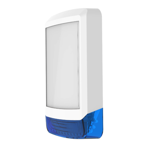
1.0 Introduction Odyssey X is a new range of modular external warning devices available in standard or backlit variants. The modular design allows for a choice of front covers to be installed on the common backplate. Please see the specification table for full details of each model. -
Page 5: Covers Options
Red or White 1.3 Graphic Inserts Odyssey X sounders can accommodate a graphic insert, rather than traditional screen printed lids. Graphic inserts can be ordered directly from Texecom. Simply follow the instructions and submit your artwork at the following web address. http://www.texe.com/uk/branding.php Once you have approved and paid for the artwork, inserts will be delivered directly to you. -
Page 6: Accessing The Unit
Select the desired Install the control Select the desired location location for the sounder panel/wireless receiver for the deterrent Install 8 core cable Learn all other If using battery power, from the sounder witeless devices, and install the batteries and location back to the install them in their final move the power select... - Page 7 The Lid has two parked positions INS627-8 7/44...
- Page 8 Undo the screw and press the tab to access Wiring & Tamper INS627-8 8/44...
- Page 9 Inner cover open INS627-8 9/44...
-
Page 10: Removing The Lid Completely
1.6 Removing the lid completely To completely remove the lid pull the lid to the left or right at the hinge points shown and then lift off. INS627-8 10/44... -
Page 11: Inserting The Odyssey X1 Graphic
1.7 Inserting the Odyssey X1 graphic (available separately, see chapter 1.3) Removing the light diffuser Gently flex the two sides of the lid outwards so that the tabs release from the lid. Lift the light diffuser upwards to release. Please make sure this operation is done in a clean dry environment. where the diffuser and lid are not likely to be scratched or damaged. - Page 12 3. Replace the light diffuser Insert the light diffuser at the top edge underneath the lugs as shown. Lower the light diffuser ensuring the two bottom side clips are engaged. INS627-8 12/44...
-
Page 13: Inserting The Odyssey X3 Graphic
1.8 Inserting the Odyssey X3 graphic (available separately, (see chapter 1.3) 1. Removing the light diffuser Gently flex the two sides of the lid outwards to release the light diffuser at point A. Push the lens tabs inwards to disengage the light diffuser. Lift the light diffuser upwards to release. - Page 14 2. Insert the Graphic Place the graphic face down in the window recess as shown. INS627-8 14/44...
- Page 15 3. Replace the light diffuser Insert the light diffuser at the top edge underneath the lugs as shown. Lower the light diffuser ensuring the two lens tabs are engaged. Press down on light diffuser shown at point C to click into place. INS627-8 15/44...
-
Page 16: Odyssey X-W (Premier Elite V2.11.X Or Later) Battery Insertion & Learning Procedure
1.9 Odyssey X-W (Premier Elite V2.11.X or later) Battery Insertion & Learning procedure When installing a wireless sounder, the batteries should be installed and the device learned to the panel BEFORE it is mounted in the chosen location. The sounder should always be the last fixed device learned and installed. - Page 17 Make Jumper selection for LED ON/OFF Make Jumper Selection for Sounder Time Odyssey X-W PCB Layout INS627-8 17/44...
- Page 18 All eight batteries (supplied) must be installed with the correct polarity. Failure to do so will result in the device reporting a battery fault. If 1-2 batteries INS627-8 18/44...
-
Page 19: Learning The Sounder (Odyssey X-W Only)
are incorrectly fitted the firmware will detect this on power up and flash both comfort LED’s for approximately 10 minutes. While the unit is in this state it will not learn to a panel. After approximately 10 minutes the unit will power off in order to save energy. -
Page 20: Led Indications (Odyssey X-W Only)
If you need to delete the device from the system you should first put it into "hold off " mode and remove the batteries. If the device will not learn to the system check that all batteries are installed correctly. 1.11 LED Indications (Odyssey X-W only) The Odyssey X-W LEDs aid in the installation of the device and act as status indicators. -
Page 21: Mounting The Unit (All Models)
1.12 Mounting the Unit (all models) Select a suitable position to mount the unit, which satisfies the following criteria: Highly prominent for maximum deterrence Additional shelter (e.g. under the eaves) is an advantage High enough to be out of normal reach to deter tampering Safe ladder access Good cable access In addition to the two adjustable screw fixing points, the unit also has a central... - Page 22 Keyhole fixing The keyhole fixing is accessed by opening the inner cover as described in the previous section. Make sure to adjust the tamper screw correctly before fully tightening this screw. Side fixings INS627-8 22/44...
-
Page 23: Adjusting Removal From Mounting Tamper
The two side fixings will lock into place when the screw is tightened. With the unit in place and hung from the keyhole fixing, you can drill anywhere in the open area to obtain the optimum fixing point. 1.14 Adjusting removal from mounting tamper The removal from mounting tamper screw must be used on all surfaces;... -
Page 24: Internal Lid Tamper
1.15 Internal Lid Tamper The Odyssey X is fitted with an internal lid tamper to prevent access to the electronics and wiring of the unit. The screw located on the inside of the internal hinged lid should be not be adjusted under normal operation. Should the device be mounted on uneven surface the screw can be adjusted to engage the tamper, but should not protrude the plastic by more than 0.5cm (measured to the highest point of the screw) -
Page 25: Wiring The Unit
1.16 Wiring the Unit Connect the unit to the control panel as follows: A (12V) Permanent Positive Supply B (BELL) Negative Applied Output to Activate Siren C (TAMP) Negative Removed on Tamper Input D (0V) Permanent Negative Supply S (STRB) Negative Applied Output to Activate Strobe T (Test) Test input for enabling remote test via Maintex or Wintex*... - Page 26 Texecom's range of control panels. For safety reasons, each Texecom sounder and strobe unit incorporates a unique patented engineer Hold‑Off mode. This mode prevents the unit from self-activating during installation and maintenance, thereby allowing only bona fide engineers...
-
Page 27: Grade 3 Wiring (Odyssey X & X-B Only)
Grade 3 to monitor the status of the battery, the supply voltage and the integrity of the trigger wire. The two diagrams below show wiring configurations for Texecom control panels, and other manufacturers, you should however ensure that your chosen control panel can support the additional requirements. - Page 28 INS627-8 28/44...
- Page 29 To comply with EN50131 requirements at Grade 3 the bell trigger should be pulled high by the control equipment. When connecting to some third party systems, or using a relay output a 1kΩ resistor should be connected between the bell trigger and the positive supply at the control panel. INS627-8 29/44...
-
Page 30: Jumper Selection (Where Available)
Prolonged “battery first” connection without power from the control panel may cause permanent damage to the internal battery. Texecom recommend that the unit is initially powered on battery only for no longer than 24 hours. -
Page 31: Backlight Wiring Options
When selecting SCB mode the battery must be connected before power is supplied from the control panel. If a unit is powered from a control panel with SCB mode selected but without the battery connected, the unit will not operate correctly due to the lack of power provided. - Page 32 If the first unit is opened it will self-activate and a tamper will be signalled to the control panel. If the second unit is opened both units will self-activate and a tamper will be signalled to the control panel. If more than one unit is connected to an installation, the current demand may exceed the rated current output of the control panel.
-
Page 33: Odyssey X-Bd
1.21 Odyssey X-BD The Odyssey X-BD can be wired or battery powered Wired Provides backlight and comfort LED's that match the flash rate of our wired sounders Battery Powered Provides comfort LED's only that match the flash rate of our wireless sounders Note: when wired, please ensure the jumper is moved to the Line position and the... - Page 34 INS627-8 34/44...
-
Page 35: Commissioning
1.22 Commissioning Most control panels have a method of testing the siren and strobe, which should be utilised for final testing. Failing this, simply arm the system and cause an alarm to confirm correct operation. Temporarily disconnect the positive supply to the unit at the control panel to confirm that the sounder self-activates. - Page 36 is invoked either by activating and de-activating the strobe three times within 30 seconds, or by pressing the B/O key when in the bell test menu. Most control panels have a method of testing the strobe, which should be utilised. Failing this the strobe can be manually activated by connecting the S (STRB) wire to 0V at the control panel.
-
Page 37: Safety
3.0 Safety INSTALLATION AND MAINTENANCE BY QUALIFIED SERVICE PERSONNEL ONLY All strobes produce hazardous voltages. However, the unit includes dual circuit safety interlocks. When the strobe is de-activated it invokes a final flash to discharge the high voltage. Back-up circuitry guarantees discharge of the high voltage within 3 minutes. -
Page 38: Technical Specification
The piezo drive produces high voltages when the siren is sounding. While not directly hazardous, these voltages will cause discomfort and should be avoided, particularly when using tools or a ladder. The piezo transformer TF1 and surrounding components will be hot during and after sounding. - Page 39 Physical Backplate All Models 3mm Polycarbonate Covers All Models 3mm Polycarbonate/3mm PMMA Tamper Detection All models Wall & Inner cover Lid dimensions (h x w x d) 290mm x 276mm x 58mm 290mm x 186mm x 58mm Module Dimensions (h x w 287mm x 170mm x 51mm Packed Weight Module only (Not X-W)
- Page 40 Voltage 7.2Vdc (nominal) Capacity 250mAh Flash Tube 1Ws Xenon Flash Rate 1Hz (typical) Discharge Time(≤60Vdc) (≤180 seconds) Comfort LED's High Intensity White Brightness 100mcd (typical) Flash Rate (tamper secure) 1Hz alternating (typical) Electrical Wireless Supply Voltage 12Vdc Operating Voltage range 11 - 15Vdc Low voltage value 11.1Vdc @25°...
-
Page 41: Standards
Total alarm current = Quiescent + Strobe + Sounder current. 3.2 Standards Texecom declares that this product complies with the requirements of the following directives 2014/53/EU RE Directive... -
Page 42: Warranty
Odyssey X-BD Backlit Deterrent. 3.3 Warranty All Texecom products are designed for reliable, trouble-free operation. Quality is carefully monitored by extensive computerised testing. As a result the Odyssey X range is covered by a two year warranty (excludes batteries) against defects in material or workmanship (details on request). - Page 43 Questa istruzione in italiano Esta instrucción en español Esta instrução em português INS627-8 43/44...
- Page 44 INS627-8 44/44...
Need help?
Do you have a question about the Odyssey X Series and is the answer not in the manual?
Questions and answers