
Subscribe to Our Youtube Channel
Related Manuals for OSD NETWORKS OSD2184P


Summary of Contents for OSD NETWORKS OSD2184P
- Page 1 Operator Manual OSD2184P / PW Micro 10/100/1000Base-T to 100/1000Base-X 3-Port Switch with IEEE802.3af/at/bt & PoH PoE Source...
- Page 3 FIGURE 14: CLI – VERSION CHECK ..................... 23 FIGURE 15: CLI – POE DUMP ....................... 23 FIGURE 16: CLI – IP CONFIGURATION ....................24 FIGURE 17: CLI – DEFAULT SETTING ....................24 PAGE 3 10120802 OSD2184P / PW Operator Manual...
- Page 4 TABLE 2: POWER CONNECTION ......................13 TABLE 3: LED FUNCTION ........................14 TABLE 4: 3-WAY DIP SWITCH SETTINGS .................... 15 TABLE 5: POE MODE ..........................16 TABLE 6: CLI COMMAND LIST ......................22 PAGE 4 10120802 OSD2184P / PW Operator Manual...
-
Page 5: Technical Summary
VOIP phones to be easily connected to your network. With a compact design the OSD2184P can easily be mounted inside a network enclosure or a Smart Pole using the DIN rail or wall mounting brackets provided. Additionally, the OSD2184PW version can be powered from a 12VDC to 57VDC supply. -
Page 6: Typical System Design
1.2 TYPICAL SYSTEM DESIGN Figure 1 below indicates a possible set-up for an OSD2184P/PW system. FIGURE 1: TYPICAL SYSTEM DESIGN PAGE 6 10120802 OSD2184P / PW Operator Manual... -
Page 7: Technical Specifications
Speed, duplex mode, ink status, auto negotiation status Port Security Individual port partner MAC address allocation (manual entry) Warranty Warranty Period 5 Years MTBF (Ground Benign 455,000 hours for OSD2184P Environment, 30ºC 402,000 hours for OSD2184PW PAGE 7 10120802 OSD2184P / PW Operator Manual... - Page 8 BT with PoH Enable BT PoH Like on all Class Enable BT Special Class 4 Enable *PoE Configurable parameters via Web-GUI PoE Output Power Budget (Total Power of Two Copper Ports) with temperature derating PAGE 8 10120802 OSD2184P / PW Operator Manual...
- Page 9 PAGE 9 10120802 OSD2184P / PW Operator Manual...
-
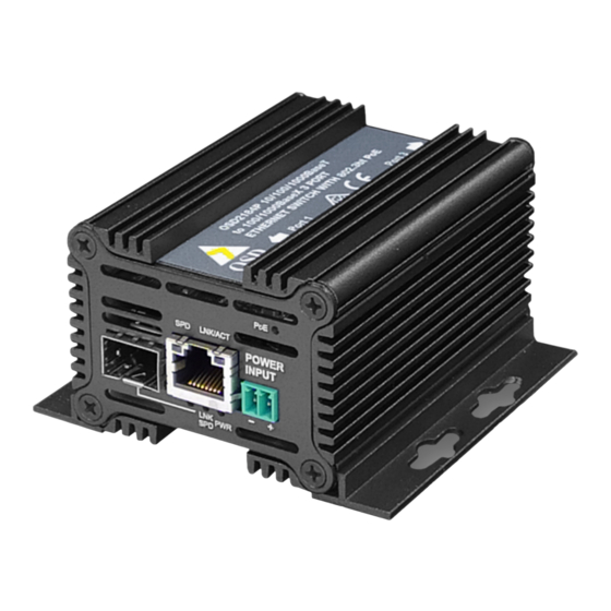
Page 10: Front / Rear Panel Layout
Each section will be described further throughout this manual. Front Panel RJ45 Port Power Input SFP Port Rear Panel PoE Mode RJ45 Port Push button Earth Screw 3-Way DIP switch USB port Erase/Restore Push Button FIGURE 2: PANEL LAYOUT PAGE 10 10120802 OSD2184P / PW Operator Manual... -
Page 11: Installation
2 INSTALLATION AND OPERATION 2.1 INTRODUCTION This section outlines the methods required to install and operate the OSD2184P/PW successfully. It should be studied carefully if damage to the equipment or poor results are to be avoided. This equipment has been fully tested prior to dispatch and is ready for immediate operation. -
Page 12: Drawings And Dimensions
2.2.2 DRAWINGS AND DIMENSIONS The OSD2184P/PW is designed to be wall mounted onto a DIN-Rail (35mm top hat) fixture or by using 4 x M4 captivated screws (DIN Rail mount requires removal and flanges repositioned – see below). The unit dimensions (excluding connectors, SFPs, etc) is shown in below. -
Page 13: Power Supply Connections
2.2.3 LOCATION As with any electrical device, the OSD2184P/PW should be placed where the switch will not be subjected to extreme temperatures, humidity, or electromagnetic interference. Specifically, the site selected should meet the following requirements: • The ambient temperature should be between -40°C to 75°C. -
Page 14: Led Indicators
No PoE Invalid Device Notes: When PoE LED is on it indicates that the unit is supplying power to the PSE Invalid device – No PoE output Activity indicates traffic for copper port PAGE 14 10120802 OSD2184P / PW Operator Manual... - Page 15 2.2.6 CONTROLS The OSD2184P/PW has a number of control functions: a 3-Way DIP Switch and a PoE Mode push button and Erase/Restore push button 3-Way DIP Switch PoE Mode Push Button FIGURE 6: CONTROLS FIGURE 7: 3-WAY DIP SWITCH TABLE 4: 3-WAY DIP SWITCH SETTINGS...
- Page 16 4 Pair power output, 90W Max, High Inrush PoH Mode Current Mode off 2 Pair power output, 30W Max, High Inrush BT Mode Current Mode off Custom There are no customized settings - this mode Mode will be skipped. PAGE 16 10120802 OSD2184P / PW Operator Manual...
-
Page 17: Fitting Sfp Connectors
Removing SFP – Remove fiber connector or RJ45 plug. Pull the SFP lever down to unlock SFP from housing. Using the lever, gently pull the SFP out. Fiber SFP Inserting Removing Copper SFP Inserting Removing FIGURE 8: FITTING/REMOVING SFP CONNECTORS PAGE 17 10120802 OSD2184P / PW Operator Manual... - Page 18 2.3 SINGLE/DUAL SIGNATURE PD OPERATION The OSD2184P/PW supports single, dual or either single/dual signature PD by automatically detecting the user PD signature. 2.3.1 SINGLE SIGNATURE PD A “single signature PD” shares the same detection signature, classification signature, and maintains power signature between both pair sets.
- Page 19 The OSD2184P/PW complies with IEEE802.3af/at and IEEE802.3bt HDBaseT standards, and is capable of supplying up to 90W of PoE per RJ45 port. The OSD2184P supports Alternative A & B (pins 1/2, 3/6 & 4/5, 7/8). Four pair output mode transmits power over all 8 pins.
-
Page 20: Operation
2.4 OPERATION When using the OSD2184P/PW for the first time, check that the unit is in good condition with no visible damage. Upon power up check that the indicators illuminate accordingly on power up (see Table 3). 2.4.1 CONNECTIONS For RJ45 connection use Category 5 (CAT5) or higher. Length should be no more than 100 meters. -
Page 21: Command Line Interface (Cli)
The Command Line Interface (CLI) is a useful tool for checking link status and debugging link connections. To enable the use of CLI, the OSD2184P must be connected to a PC with a USB port via a Mini USB to (typically) USB Type A cable. Using a terminal emulation program such as hyperterminal or SSCOM, a number of command lines specific to the OSD2184P can be implemented. -
Page 22: Command Line Functions
Displays current IP, Mask and ipconfig IP Configuration Gateway. Provides ability to change Figure 16 the IP settings. Allows the user to reset the unit to Default Setting Figure 17 factory default. PAGE 22 10120802 OSD2184P / PW Operator Manual... -
Page 23: Version Check
PoE Dump - <poe_dump> FIGURE 15: CLI – POE DUMP Displays the current PoE output status of the following; Port PS Type Current Voltage Power Requested Power Assigned Class on AlternativeA Class on AlternativeB Status PAGE 23 10120802 OSD2184P / PW Operator Manual... -
Page 24: Default Setting
– Exits the default configuration setting and returns to the home prompt. y – Resets to default configuration sequence. The unit will require a reboot (see Page 33) for changes to take effect. PAGE 24 10120802 OSD2184P / PW Operator Manual... - Page 25 2.6 WEB GUI The OSD2184P/PW provides a web-based browser interface for configuring and monitoring the unit. This interface allows you to access the switch using any preferred web browser. This chapter describes how to configure the switch using its web-based browser interface.
-
Page 26: Logging On To The Switch
A table displaying system information is also displayed containing MAC address, Serial Number, Software, IP address, etc. 2.6.2 GUI MENU The user has access to Configure, Monitor or Maintain the OSD2184P/PW. Each section will be explained within this manual. PAGE 26 10120802... - Page 27 Current: Displays the current saved Subnet Mask EFAULT ATEWAY Configured: The Default Gateway can be changed by modifying this window. Current: Displays the current saved Default Gateway Buttons : saves the new settings : resets any changes made PAGE 27 10120802 OSD2184P / PW Operator Manual...
- Page 28 EGACY EVICE The OSD2184P provides legacy PoE support. A blue button indicates the Enable/Disable setting. The OSD2184P provides the user to select 2 pair or 4 pair. A blue button indicates the setting. AXIMUM OWER The user can set the output maximum power to each port. A blue button indicates the setting.
- Page 29 A drop down window allows the user to select the desired log event setting. • Disable: No information is logged from that module • Info: Some basic information is logged • Debug: Diagnostic information logged Buttons : saves the new settings PAGE 29 10120802 OSD2184P / PW Operator Manual...
- Page 30 Up: Connection established Down: No Connection detected PEED Indicates the port connection speed in Mbps. • 10: 10Mbps • 100: 100Mbps • 1000: 1000Mbps (1Gbps) UPLEX Indicates port connection type. Full, Half PAGE 30 10120802 OSD2184P / PW Operator Manual...
- Page 31 Indicates the class type on Alternative A from the relevant PoE port/channel LASS ON LTERNATIVE Indicates the class type on Alternative B from the relevant PoE port/channel TATUS Indicates the detected PD class on the relevant port/channel PAGE 31 10120802 OSD2184P / PW Operator Manual...
- Page 32 This process takes several seconds. The webpage will redirect to the “System Information” page. Please check this page to ensure that the Software ID Number has been uploaded by the new software. Buttons : Browse file location : Upload software PAGE 32 10120802 OSD2184P / PW Operator Manual...
- Page 33 Click the Upload button. The firmware will be uploaded to the unit. Please wait until firmware has been uploaded completely as shown below and wait until the system has rebooted. → S AINTANANCE YSTEM EBOOT Use this section to reboot the unit Buttons : Reboots the unit PAGE 33 10120802 OSD2184P / PW Operator Manual...
-
Page 34: External Inspection
3 MAINTENANCE 3.1 INTRODUCTION The following section outlines the fault-finding procedure for the OSD2184P/PW modems. Please take note of the following: ▲ Personnel without appropriate training should not attempt any maintenance except that outlined below. ▲ If further maintenance is attempted you are warned that every care should be taken to... -
Page 35: Warranty Period
All modifications are to be carried out by OSD Technicians. Warranty is void if unauthorized removal and/or tampering with serial number and/or repair labels is evident. PAGE 35 10120802 OSD2184P / PW Operator Manual... - Page 36 Optical Systems Design Pty. Ltd. 7/1 Vuko Pl. Warriewood 2102 P.O. Box 891 Mona Vale N.S.W. Australia 2103 Telephone: +61 2 9913 8540 Facsimile: +61 2 9913 8735 Email: sales@osd.com.au Web Site: www.osd.com.au Printed in Australia...
Need help?
Do you have a question about the OSD2184P and is the answer not in the manual?
Questions and answers