
Related Manuals for OSD NETWORKS OSD2524P


Summary of Contents for OSD NETWORKS OSD2524P
- Page 1 Quick Start Guide OSD2524P Layer Managed 26-port Ethernet Switch With 4 x Combo & 2 x Gb SFP Ports With IEEE802.3bt PoE...
- Page 3 FIGURE 6: CLI INSTALLATION ...................... 12 FIGURE 7: PORT/LED ........................13 FIGURE 8: FITTING/REMOVING SFP CONNECTORS ..............15 TABLE 1: TECHNICAL SPECIFICATIONS ..................6 TABLE 2: POWER CONNECTION ....................11 TABLE 3: LED FUNCTION ......................14 PAGE 3 10120901 OSD2524P Quick Start Guide...
- Page 4 ▲ IEEE802.3bt Compliant With an overall PoE power budget of 720W the OSD2524P can be deployed in a wide range of communication networks. 8 ports are IEEE802.3bt compliant with each providing up to 90W per port to support the latest IP PTZ cameras, Wireless Access Points, Thin Clients, PoE lighting and other powered devices.
- Page 5 1.2 TYPICAL SYSTEM DESIGN Figure 1 below indicates a possible set-up for an OSD2524P system. FIGURE 1: TYPICAL SYSTEM DESIGN 1.3 TECHNICAL SPECIFICATIONS PAGE 5 10119802 OSD2524P Quick Start Guide...
- Page 6 GUI controlled for each individual port Managements Configuration download or upload. Dot3-OAM-MIB RFC 1213 MIB LLDP-MED power MIB Bridge MIB MSTP MIB LLDP MIB Private MIB Framework Contact OSD for full list of MIBs PAGE 6 10119802 OSD2524P Quick Start Guide...
- Page 7 Disable, Standard mode (802.3af/at), Legacy support Environmental Operating Temperature -20 to +70ºC Relative Humidity 5 to 95% non-condensing Warranty Warranty Period 5 years MTBF (Ground Benign Environment, 160,000 hours (360W power consumption @ 30ºC) 30ºC) PAGE 7 10119802 OSD2524P Quick Start Guide...
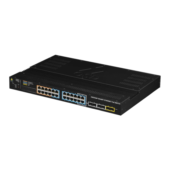
- Page 8 4 x SFP Console View Reset Port Push IEEE802.3bt IEEE802.3af/at Push Button RJ45 x 8 RJ45 x 16 Button Rear Panel Dual Redundant DC Power Power LED x 2 Earth Screw FIGURE 2: FRONT/REAR PANEL PAGE 8 10119802 OSD2524P Quick Start Guide...
- Page 9 2 INSTALLATION AND OPERATION 2.1 INTRODUCTION This section outlines the methods required to install and operate the OSD2524P successfully. It should be studied carefully if damage to the equipment or poor results are to be avoided. This equipment has been fully tested prior to dispatch and is ready for immediate operation.
- Page 10 2.2.2 DRAWINGS AND DIMENSIONS The OSD2524P is designed to be desk mounted or 19” rack mountable. The unit dimensions (excluding connectors, SFPs, etc) is shown in Figure 3 below. FIGURE 3: MOUNTING DIMENSIONS PAGE 10 10119802 OSD2524P Quick Start Guide...
- Page 11 2.2.3 LOCATION As with any electrical device, the OSD2524P should be placed where the switch will not be subjected to extreme temperatures, humidity, or electromagnetic interference. Specifically, the site selected should meet the following requirements: • The ambient temperature should be between -20°C to 70°C.
- Page 12 2.2.5 USB CONNECTOR The OSD2524P has a mini USB connector located on the front of the unit that is used for Command Line Interface (CLI) from the PC to the OSD2524P via the PC’s USB connector. See section 2.4 for further CLI information.
- Page 13 *The View Push Button when pressed will cycle through Link/Speed, Link/Duplex, Link/Status, PoE. This will indicate the Port LED (1-24) function. SFP Combo Port SFP Trunk Port LED x 4 LED x 2 Power 1 LED Power 2 LED FIGURE 7: PORT/LED PAGE 13 10119802 OSD2524P Quick Start Guide...
- Page 14 No Connection Green Power Connected Power 1 / Power 2 No Power connected Note: Ports 21-24 are Combo ports, Either the fixed RJ45 port or the SFP ports are operational at one time. PAGE 14 10119802 OSD2524P Quick Start Guide...
- Page 15 Removing SFP – Remove fiber connector or RJ45 plug. Pull the SFP lever down to unlock SFP from housing. Using the lever, gently pull the SFP out. Fiber SFP Inserting Removing Copper SFP Inserting Removing FIGURE 8: FITTING/REMOVING SFP CONNECTORS PAGE 15 10119802 OSD2524P Quick Start Guide...
- Page 16 2.3 OPERATION When using the OSD2524P for the first time, check that the unit is in good condition with no visible damage. Upon power up check that the indicators illuminate accordingly on power up (see Table 3). 2.3.1 CONNECTIONS For RJ45 connection use Category 5 (CAT5) or higher. Length should be no more than 100 meters.
- Page 17 The Command Line Interface (CLI) is a useful tool for checking link status and debugging link connections. To enable the use of CLI the OSD2524P must be connected to a PC with a serial port and an appropriate cable as specified in section 2.2.5. Using a terminal emulation program such as Hyperterminal, a number of command lines specific to the OSD2524P can be implemented to check link/node status, ring/bus topology and enable/disable float backup.
- Page 18 Note that there are sub-commands for every 1 level commands eg. # clear ? will display all sub command arguments associated with the clear command. The CLI will then display # clear and wait for the sub command. PAGE 18 10119802 OSD2524P Quick Start Guide...
- Page 19 When the unit is in configuration mode, the user can change detailed configurations. To set the OSD2524P host name, the unit needs to be first set to configuration mode then enter the hostname command, then a chosen hostname. After this is entered, the unit requires an ‘exit’...
- Page 20 It is necessary to save any changes to FLASH storage in the ‘startup-config’ otherwise the changes will not take effect when the unit is powered off. To save the changes the configuration needs to be copied to the startup configuration. # copy running-config startup-config PAGE 20 10119802 OSD2524P Quick Start Guide...
- Page 21 The Quick Start Guide section will only show a few main or important features to get the user started and running the OSD2524P successfully. On the top right hand of the GUI screen there are three icons available to quickly navigate or obtain help for each GUI menu item. The Quick Start Guide also assumes user knowledge for complex switch settings.
- Page 22 Click Save to save the configuration. Use new IP address to access the switch. PS: All configuration changes must be saved otherwise all the changes will be lost after rebooting! See section 3.1.5. PAGE 22 10119802 OSD2524P Quick Start Guide...
- Page 23 Click admin to change the current admin account setting. If multiple users are required, click Add New User PS: All configuration changes must be saved otherwise all the changes will be lost after rebooting! PAGE 23 10119802 OSD2524P Quick Start Guide...
- Page 24 Disable: No PoE output. Port Configuration\Priority: Changes the priority according to the setting. Factory Default Configuration\PoE Set as PoE Max. PoE output Power. Capacitor Detection: Enable. PoE\Standard. Ports set as Auto for all Ports. PAGE 24 10119802 OSD2524P Quick Start Guide...
- Page 25 4 MAINTENANCE 4.1 INTRODUCTION The following section outlines the fault-finding procedure for the OSD2524P modems. Please take note of the following: ▲ Personnel without appropriate training should not attempt any maintenance except that outlined below. ▲ If further maintenance is attempted you are warned that every care should be taken to...
- Page 26 All modifications are to be carried out by OSD Technicians. Warranty is void if unauthorized removal and/or tampering with serial number and/or repair labels is evident. PAGE 26 10119802 OSD2524P Quick Start Guide...
- Page 27 PAGE 27 10119802 OSD2524P Quick Start Guide...
- Page 28 Optical Systems Design Pty. Ltd. 7/1 Vuko Pl. Warriewood 2102 P.O. Box 891 Mona Vale N.S.W. Australia 2103 Telephone: +61 2 9913 8540 Facsimile: +61 2 9913 8735 Email: sales@osd.com.au Web Site: www.osd.com.au Printed in Australia...
Need help?
Do you have a question about the OSD2524P and is the answer not in the manual?
Questions and answers