
Related Manuals for OSD NETWORKS OSD2254EP


Summary of Contents for OSD NETWORKS OSD2254EP
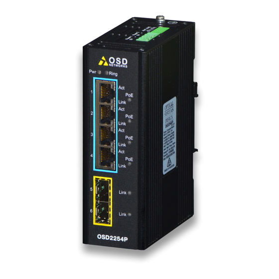
- Page 1 Operator Manual OSD2254EP Lite Managed 6-port Ethernet Switch with SNMP & VLAN 4 x 10/100/1000BASE-T with PoE++ & 2 x Gigabit SFP...
- Page 3 FIGURE 10: PORT/LED ......................15 FIGURE 11: CONTROLS ......................16 FIGURE 12: 8-WAY DIP SWITCH ................... 16 FIGURE 13: FITTING/REMOVING SFP CONNECTORS ............18 FIGURE 14: REDUNDANT RING CONFIGURATION ............. 19 FIGURE 15: REDUNDANT RING CONNECTION ..............20 PAGE 3 10115208 OSD2254EP Operator Manual...
- Page 4 TABLE 3: ALARM CONNECTIONS ..................12 TABLE 4: LED FUNCTION....................... 15 TABLE 5: 8-WAY DIP SWITCH SETTINGS ................16 TABLE 6: POE MODE SWITCH SETTINGS ................17 TABLE 7: TERMINAL COMMAND LINES ................22 PAGE 4 10115208 OSD2254EP Operator Manual...
-
Page 5: Technical Summary
1.1.1 OVERVIEW The OSD2254EP is a 6-port lite managed industrial ethernet switch with four Gigabit RJ45 and two Gigabit SFP uplink ports which can be used as standard ports or as a redundant fiber ring using OSD’s proprietary ring protocol. Each RJ45 can provide up to 60W PoE to power a wide range of devices. Along with higher level features including SNMP, VLAN and IGMP snooping the OSD2254EP is suitable for use in critical networks. -
Page 6: Typical System Design
1.2 TYPICAL SYSTEM DESIGN Figure 1 below indicates a possible set-up for an OSD2254EP system. FIGURE 1: TYPICAL SYSTEM DESIGN PAGE 6 10115208 OSD2254EP Operator Manual... -
Page 7: Technical Specifications
MAC address binding VLAN 802.1Q VLAN Multicast Protocol RFC 2236 IGMP snooping v1, v2, v3 Ethernet Redundancy OSD-Ring SNMP MIBs RFC 1213 MIB Warranty Warranty Period 5 years MTBF (Ground Benign Environment, 480,000 hours 30ºC) PAGE 7 10115208 OSD2254EP Operator Manual... -
Page 8: Port Allocation
SFP Port x 2 Link LED x 2 Alarm Port Dual Power Top Panel Port Earth Screw Power Supply LED x 2 Console Port Bottom Panel Programming Port Configuration Switches FIGURE 2: PORT ALLOCATION PAGE 8 10115208 OSD2254EP Operator Manual... -
Page 9: Installation
2 INSTALLATION AND OPERATION 2.1 INTRODUCTION This section outlines the methods required to install and operate the OSD2254EP successfully. It should be studied carefully if damage to the equipment or poor results are to be avoided. This equipment has been fully tested prior to dispatch and is ready for immediate operation. -
Page 10: Drawings And Dimensions
2.2.2 DRAWINGS AND DIMENSIONS The OSD2254EP is designed to be wall mounted onto a DIN-Rail (35mm top hat) fixture or by using 4 x M4 captivated screws (DIN Rail mount requires removal and flanges repositioned – see below). The unit dimensions (excluding connectors, SFPs, etc) is shown in Figure 3 below. -
Page 11: Power Supply Connections
2.2.3 LOCATION As with any electrical device, the OSD2254EP should be placed where the switch will not be subjected to extreme temperatures, humidity, or electromagnetic interference. Specifically, the site selected should meet the following requirements: • The ambient temperature should be between -40°C to 75°C. -
Page 12: Alarm Connection
2.2.5 ALARM CONNECTION The OSD2254EP has two monitoring alarm outputs: 1) Ring to Bus Alarm and 2) Temperature Alarm. The alarm connections and conditions for alarm outputs are as set out in Table 3. There are four pins on the 3.5mm terminal block used alarm output. Maximum ratings the OSD2254EP relay can drive is 100mA @ 46V . -
Page 13: Usb Connector
2.2.6 USB CONNECTOR The OSD2254EP has a USB – Type B connector located on the bottom of the unit that is used for Command Line Interface (CLI) from the PC to the OSD2254EP via the PC’s USB connector. See section 2.4 for further CLI information. -
Page 14: Mini Usb Port
2.2.7 MINI USB PORT The Mini USB Port is used for uploading firmware updates. All OSD2254EP units will be shipped with the latest firmware already installed. This port has no function for end user. Mini USB Port FIGURE 9: USB CONNECTOR... -
Page 15: Led Indicators
No Activity 1G/100M/10Mbps PoE Load No Load Detected Link No Link Fiber Link Activity No Link 1Gbps 100Mbps Power Power On Supply 1 Connected Power Power On Supply 2 Connected PAGE 15 10115208 OSD2254EP Operator Manual... - Page 16 2.2.9 CONTROLS The OSD2254EP has an 8-way DIP switch to control a number of functions. Table 5 outlines the function of each switch. 8-Way DIP Switch FIGURE 11: CONTROLS FIGURE 12: 8-WAY DIP SWITCH TABLE 5: 8-WAY DIP SWITCH SETTINGS...
- Page 17 Two PoE channels provide power (mode 100, 101, 110): Max output power is 90W For 802.3at/af standard mode (000), power limitation follows the classification result ie 802.3at/af standard. For reserved modes (011, 111), PoE function is disabled on each port. PAGE 17 10115208 OSD2254EP Operator Manual...
-
Page 18: Fitting Sfp Connectors
Removing SFP – Remove fiber connector or RJ45 plug. Pull the SFP lever down to unlock SFP from housing. Using the lever, gently pull the SFP out. Fiber SFP Inserting Removing Copper SFP Inserting Removing FIGURE 13: FITTING/REMOVING SFP CONNECTORS PAGE 18 10115208 OSD2254EP Operator Manual... -
Page 19: Operation
2.3 OPERATION When using the OSD2254EP for the first time, check that the unit is in good condition with no visible damage. Upon power up check that the indicators illuminate accordingly on power up (see Table 4). 2.3.1 CONNECTIONS For RJ45 connection use Category 5 (CAT5) or higher. Length should be no more than 100 meters. - Page 20 FIGURE 15: REDUNDANT RING CONNECTION Bus Operation To connect the OSD2254EP in a bus configuration ports 5 and 6 must be used together with fiber SFPs. The remaining ports (ports 1,2,3 & 4) should be used to connect to your Ethernet devices (eg.
-
Page 21: Command Line Interface
The Command Line Interface (CLI) is a useful tool for checking link status and debugging link connections. To enable the use of CLI the OSD2254EP must be connected to a PC with a serial port and an appropriate cable as specified in section 2.2.6. Using a terminal emulation program such as Hyperterminal, a number of command lines specific to the OSD2254EP can be implemented to check link/node status, ring/bus topology and enable/disable float backup. -
Page 22: Command Line Functions
COMMAND LINE FUNCTIONS There are a number of command line functions that enables the user to obtain running information of a single OSD2254EP unit or the complete topology of the ring/bus network. This section explains the command lines and its functions. -
Page 23: Version Check
VERSION CHECK - <vc> FIGURE 18: VERSION CHECK Displays useful information regarding the unit: Software Version Number Software ID Number Build Time Product Name PAGE 23 10115208 OSD2254EP Operator Manual... -
Page 24: Factory Default
FACTORY DEFAULT - <fd> FIGURE 19: FACTORY DEFAULT SETTING Resets the OSD2254EP to its default factory setting. A prompt question will appear “Do you want to Reset Configuration [y/n]? n – Exits the default configuration setting and returns to the home prompt. - Page 25 Displays the current IP address, Net mask and Gateway settings. To make changes to the IP address, Net mask and Gateway, at the prompt enter the new details in the following format; ipconfig <ip address> <netmask> <gateway address> PAGE 25 10115208 OSD2254EP Operator Manual...
- Page 26 TOPOLOGY CHECK - <tc> FIGURE 21: TOPOLOGY CHECK In this case, only one OSD2254EP is connected to the USB cable. The display indicates the following; No: 1 – Number of units connected on the ring/bus (in this case only one unit) MAC_ADDRESS: 00:26:dc:00:1e:28 –...
- Page 27 In the example below there are four OSD2254EP connected in a ring configuration. FIGURE 22: TOPOLOGY CHECK No: 4 – Four units connected MAC_ADDRESS:– Displaying all the MAC addresses of the units connected on the ring/bus TOPOLOGY: Ring – Displaying type of connection.
- Page 28 FIGURE 23: NODE CHECK Node check obtains the running status of the node for the specific MAC address requested within the Ring/Bus. Correct entry format is as follows (MAC address specified below is an example); nc 00:26:dc:00:42:c6 PAGE 28 10115208 OSD2254EP Operator Manual...
- Page 29 This command line displays the running status of the local node that the USB cable is plugged into. The information provided is the MAC address, Topology, Node Role, Port Role and Float Backup status. PAGE 29 10115208 OSD2254EP Operator Manual...
- Page 30 In the event of a fiber link being broken or disconnected (indicated by a cross) the backup branch will become the active branch. If the link between node 1 and 3 is broken (see Figure 27), node 1 will communicate with node 3 via node 2 and node 4. PAGE 30 10115208 OSD2254EP Operator Manual...
- Page 31 Note: When configuring the float backup function all units on the ring/bus network must have the same float backup configuration for correct operation. Differing backup configurations will cause segmented backup branches and may not function as intended. All OSD2254EP are set to enabled float backup upon shipment. PAGE 31 10115208...
- Page 32 If the link between node 1 and 3 is broken (see Figure 30), node 1 will communicate with node 3 via node 2 and node 4. Active Branch Back- Branch FIGURE 30: FLOAT BACKUP DISABLED 2 PAGE 32 10115208 OSD2254EP Operator Manual...
- Page 33 Note: When configuring the float backup function all units on the ring/bus network must have the same float backup configuration for correct operation. Differing backup configurations will cause segmented backup branches and may not function as intended. All OSD2254EP are set to enabled float backup upon shipment. PAGE 33 10115208...
- Page 34 This command line enables the user to setup the IP for all nodes on a ring/bus. Correct entry format is as follows (MAC, IP, mask and gateway address specified below is an example); node_all_set 192.168.0.99 255.255.255.0 192.168.0.1 2 PAGE 34 10115208 OSD2254EP Operator Manual...
- Page 35 Reboot All Reboots all devices in the network. The correct reboot format is as follows; reboot/rb all Note: Reboot All should only be used when a single device reboot does not recover a network failure. PAGE 35 10115208 OSD2254EP Operator Manual...
-
Page 36: Snmp Configuration
FIGURE 35: SNMP This command line changes the root path. Typing ? will list the command lines within the SNMP directory. To return to the root directory, type in return and hit enter on the keyboard. PAGE 36 10115208 OSD2254EP Operator Manual... - Page 37 This command changes the SNMP trap community. The format is as follows; stc <trap community> Example: stc public Return to Root Directory <return> This command returns the CLI to the root directory. The format is as follows; return PAGE 37 10115208 OSD2254EP Operator Manual...
-
Page 38: Port Control
Note: A warning message will appear and prompt the user to either select yes or no to continue n – Exits the port control setting and returns to the root prompt. y – disables all 4 ports and returns to the root prompt. PAGE 38 10115208 OSD2254EP Operator Manual... -
Page 39: Port Security
The psm command displays the MAC address security function commands for each port ie. allows access to the MAC address on each port. Add – Adds MAC address psm <add> <port> <vlan> <MAC address> Delete – Delete MAC address psm <delete> <port> <vlan> <MAC address> PAGE 39 10115208 OSD2254EP Operator Manual... - Page 40 List – lists the current port security MAC address list psm <list> PAGE 40 10115208 OSD2254EP Operator Manual...
- Page 41 3 WEB GUI The OSD2254EP provides a web-based browser interface for configuring and monitoring the unit. This interface allows you to access the switch using any preferred web browser. This chapter describes how to configure the switch using its web-based browser interface.
-
Page 42: Logging On To The Switch
In your web browser, specify the IP address of the switch. Default IP address is 192.168.0.99 To access the OSD2254EP a username and password will need to be entered. Factory default username is “admin” and no password is set (leave blank) and click Login. - Page 43 3.1.2 GUI MENU The user has access to Configure, Monitor or Maintain the OSD2254EP. Each section will be explained within this manual. PAGE 43 10115208 OSD2254EP Operator Manual...
- Page 44 Location OCATION Configured: The user can set the location of the unit to easily identify its location. Last Configured: Displays last configured location Buttons : saves the new settings : resets any changes made PAGE 44 10115208 OSD2254EP Operator Manual...
- Page 45 Configured: The SNMP Trap Server IP address can be changed by modifying this window. Current: Displays the current saved SNMP Trap Server IP Address Buttons : saves the new settings : resets any changes made PAGE 45 10115208 OSD2254EP Operator Manual...
- Page 46 UTHENTICATION ASSWORD A string identifying the authentication password phrase. For MD5 authentication protocol, the allowed string length is 8 to 32. For SHA authentication protocol, the allowed string length is 8 to 40. PAGE 46 10115208 OSD2254EP Operator Manual...
- Page 47 AES: An optional flag to indicate that this user uses AES authentication protocol. RIVACY ASSWORD A string identifying the privacy password phrase. The allowed string length is 8 to 32. Buttons : Click to add new user : saves the new settings PAGE 47 10115208 OSD2254EP Operator Manual...
- Page 48 VLANs work as though they are created using independent switches. When VLAN mode is set to 802.1Q VLAN and Ring mode is enabled, port 1-4 can be configured and the VLAN configuration page will be displayed as; PAGE 48 10115208 OSD2254EP Operator Manual...
- Page 49 VLANs. By Default, all the ports belong to group 1. Only ports assigned to group 1 can access the WebGUI. When Ring mode is enabled port 1-4 can be configured. When Ring mode is disabled, ports 5 and 6 can also be configured. PAGE 49 10115208 OSD2254EP Operator Manual...
- Page 50 Native VLAN for ports in Trunk or Hybrid mode. VLAN (T AGGED AGGED Ports in Trunk and Hybrid mode may control which VLANs they are allowed to become members of. Access ports can only be member of one VLAN, the Access VLAN. PAGE 50 10115208 OSD2254EP Operator Manual...
- Page 51 All VLAN frames in field(except port VLAN), are transmitted with a tag. VLAN (U IXED NTAGGED All VLAN frames in this field, are transmitted without a tag. This option is only available for ports in Hybrid mode. Buttons : saves the new settings PAGE 51 10115208 OSD2254EP Operator Manual...
- Page 52 100Mbps FDX: Full Duplex • 1G FDX: Full Duplex • Disable: Port Disable Note: Port 1 to 4 are speed and full/half duplex selectable. Port 5 & 6 are enable/disable only. Buttons : saves the new settings PAGE 52 10115208 OSD2254EP Operator Manual...
- Page 53 Allows the user to manually set the Log Level to be monitored • Disable: Disables the log monitoring for selected port • Info: Displays basic log activity for selected port • Debug: Displays detailed log activity for selected port Buttons : saves the new settings PAGE 53 10115208 OSD2254EP Operator Manual...
- Page 54 Displays port number per row TATIC OUTER A drop-down menu allows user settings for the following; • Enable: Enables IGMP Static Router setting • Disable: Disables IGMP Static Router setting Buttons : saves the new settings PAGE 54 10115208 OSD2254EP Operator Manual...
- Page 55 The allowed selection from the drop-down menu is; • Auto • Forced IGMPv1 • Forced IGMPv2 • Forced IGMPv3 The default IGMP version value is IGMP-Auto Buttons : Click to add new IGMP VLAN. : saves the new settings PAGE 55 10115208 OSD2254EP Operator Manual...
- Page 56 → P ONFIGURATION Indicates port number per row. NABLED A tick indicates the PoE is enabled for the port. Buttons : saves the new settings PAGE 56 10115208 OSD2254EP Operator Manual...
- Page 57 Indicates port number per row. A drop-down menu allows user settings for the following; • Enable: Enables port security for selected port number • Disable: Disables port security for selected port number Buttons : saves the new settings PAGE 57 10115208 OSD2254EP Operator Manual...
- Page 58 A maximum of 30 entries can be added into the table. When adding the same MAC address into the same VLAN, the duplicated entry will be automatically deleted. Buttons : click to add new entry. : saves the new settings PAGE 58 10115208 OSD2254EP Operator Manual...
- Page 59 → S ONITOR YSTEM This menu is identical to the start-up menu. A table displaying useful system information is also displayed containing MAC address, Serial Number, Software, IP address, etc. PAGE 59 10115208 OSD2254EP Operator Manual...
- Page 60 Indicates the role of each ports connections: Switch Port, Ring Port, Bus Port. Up: Connection established Down: No Connection detected PEED Indicates the port connection speed in Mbps. • 10: 10Mbps • 100: 100Mbps • 1000: 1000Mbps (1Gbps) UPLEX Indicates port connection type. Full, Half PAGE 60 10115208 OSD2254EP Operator Manual...
- Page 61 Displays the IP address for each unit connected on the ring/bus ERSION Indicates the ring module software version EVICE Indicates the OSD product within the ring OCATION The location of the device can be set and displayed in this window PAGE 61 10115208 OSD2254EP Operator Manual...
- Page 62 Indicates the power drawn from the relevant PoE port/channel URRENT IMIT Indicates the maximum current limit from the relevant PoE port/channel PD C LASS Indicates the detected PD class TATUS Indicates the status of the port PAGE 62 10115208 OSD2254EP Operator Manual...
- Page 63 → S ONITOR YSTEM Monitors and logs activity Event number Records a time-stamp of the log activity A brief description of the type of event PAGE 63 10115208 OSD2254EP Operator Manual...
- Page 64 Lists the port number of devices being monitored to display status TATUS Indicates the status of the router port number Group Information VLANS VLAN ID of the group. GROUP Group address of the group displayed. EMBERS Ports under this group. PAGE 64 10115208 OSD2254EP Operator Manual...
- Page 65 It is advised to check that the unit has the uploaded software installed correctly by selecting Monitor → System Info. Check the Software ID and the Build Time (date and time of upload) is correct. Buttons : Browse file location : Upload software PAGE 65 10115208 OSD2254EP Operator Manual...
- Page 66 Enter new password again in this window. This window must match new password window in order for new password to take effect. Buttons : click save for new username and/or password settings to take effect. PAGE 66 10115208 OSD2254EP Operator Manual...
- Page 67 Clicking this button will reset the unit to factory default settings including the user name and current password. → S AINTENANCE YSTEM EBOOT Use the section to reboot the system when any switch settings are changes for the new settings to take effect. PAGE 67 10115208 OSD2254EP Operator Manual...
-
Page 68: External Inspection
4 MAINTENANCE 4.1 INTRODUCTION The following section outlines the fault-finding procedure for the OSD2254EP modems. Please take note of the following: ▲ Personnel without appropriate training should not attempt any maintenance except that outlined below. ▲ If further maintenance is attempted you are warned that every care should be taken to... -
Page 69: Warranty Period
All modifications are to be carried out by OSD Technicians. Warranty is void if unauthorized removal and/or tampering with serial number and/or repair labels is evident. PAGE 69 10115208 OSD2254EP Operator Manual... - Page 70 PAGE 70 10115208 OSD2254EP Operator Manual...
- Page 71 PAGE 71 10115208 OSD2254EP Operator Manual...
- Page 72 Optical Systems Design Pty. Ltd. 7/1 Vuko Pl. Warriewood 2102 P.O. Box 891 Mona Vale N.S.W. Australia 2103 Telephone: +61 2 9913 8540 Facsimile: +61 2 9913 8735 Email: sales@osd.com.au Web Site: www.osd.com.au Printed in Australia...
Need help?
Do you have a question about the OSD2254EP and is the answer not in the manual?
Questions and answers