
Related Manuals for Ecolab EcoPro-ES-00510X-PFC-00S-1S-S0


Summary of Contents for Ecolab EcoPro-ES-00510X-PFC-00S-1S-S0
- Page 1 Operating instructions EcoPro Ecolab Dynamic Pump EcoPro 417102264 Rev. 5-01.2019 08.01.2019 ENGLISH...
-
Page 2: Table Of Contents
Table of contents Table of contents General information....................5 1.1 Information on User Manual................5 1.2 Availability and updating of the operating instructions........5 1.3 Call up operating instructions with smartphone..........6 1.4 Article numbers / EBS-Article numbers.............. 6 1.5 Copyright......................6 1.6 Symbols, highlighting and enumerations............ - Page 3 Table of contents 6.3.3.1 Pipe and hose connection with integrated support sleeve......38 6.3.3.2 Pipe and hose connection with tapered part..........39 6.3.3.3 Pipe and hose connection with attachment nipple and hose clamp... 40 6.3.3.4 Pipe and hose connection with female coupling......... 41 6.3.4 Electrical Installation..................
- Page 4 Table of contents 12.2 LED - fault messages ..................73 Technical specifications..................74 13.1 Packaging....................... 74 13.2 Equipment marking / Type plate..............74 13.3 ‘EcoPro’ pump key..................75 13.3.1 Pump key group I..................75 13.3.2 Pump key group II..................76 13.3.3 Pump key group III..................
-
Page 5: General Information
All operating instructions are kept up to date at all times and freely available online for download. To download the instructions with a PC, tablet or Smartphone, use the links below or scan the QR code. Download of the operating instructions ‘EcoPro’ (Article No. 417102264): https://www.ecolab-engineering.de/fileadmin/download/ bedienungsanleitungen/dosiertechnik/Dosierpumpen/ 417102264-EcoPro.pdf 417102264 Rev. 5-01.2019... -
Page 6: Call Up Operating Instructions With Smartphone
"Google Play" app This app can be used to access the app store for the Android system. This can be searched for and installed by entering the app name "Ecolab DocuAPP" smartphones have the "APP Store" app This app can be used to access the app store for the Apple IOS system. - Page 7 General information WARNING! This combination of symbol and signal word indicates a potentially dangerous situation which could result in serious or fatal injury if not avoided. CAUTION! This combination of symbol and signal word indicates a potentially dangerous situation that could lead to minor or slight injuries if not avoided. NOTICE! This combination of symbol and signal word indicates a potentially dangerous situation that could lead to material damage if not avoided.
-
Page 8: Transport
General information Further markings The following markings are used in this manual to highlight operating instructions, results, collections, references and other elements: Marking Explanation 1., 2., 3..Step by step operating instructions ð Results of the operating steps References to sections of this manual and related documents Collections in no set order [Button] Controls (e.g. -
Page 9: Packaging
General information Transport inspection NOTICE! Check the delivery for completeness and any transport damage. In case of visible damage, proceed as follows: Do not accept the delivery or accept provisionally. Note down the extent of damage in the transport documents or on the delivery slip. Lodging a complaint. -
Page 10: Storage
General information Symbols on the packaging Symbol Name Description The individual package must always be transported, handled and stored in such a way that the arrows point upwards at all times. Rollers, flaps, heavy tipping or edges and other forms of handling must be avoided. -
Page 11: Warranty
The general warranty and service conditions of the manufacturer also apply. 1.12 Manufacturer's service and contact address Ecolab Engineering GmbH Raiffeisenstraße 7 D-83313 Siegsdorf, Germany Telephone (+49) 86 62 / 61 0 Fax (+49) 86 62 / 61 166 Email: engineering-mailbox@ecolab.com... -
Page 12: Safety
Safety Safety General Safety DANGER! If you assume that safe operation is no longer possible the pump must be put out of service immediately and be secured against unauthorized use. This is the case if: – is visibly damaged – appears no longer functional –... -
Page 13: Reasonable Foreseeable Incorrect Use
Safety WARNING! Danger of improper use! Improper use may result in dangerous situations: – Never use metering media other than the specified product. – Never change the product metering guidelines beyond the tolerable range. – Do not use in potentially explosive areas. –... -
Page 14: Lifetime
Safety Lifetime In relation to the dependence of the adequate maintenance protocols the life time is 2 years (visual and functional testing, replacement of wearing parts, etc.) Afterwards a revision is necessary, in some cases also a subsequent general overhaul by the manufacturer. -
Page 15: Personal Protective Equipment (Ppe)
Safety Production supervisor The production supervisor is capable of performing the work assigned to them because of their technical training, knowledge and experience, as well as awareness of the relevant standards and regulations; they are able to autonomously identify and prevent potential risks. -
Page 16: Indications Of Risks
Safety WARNING! Protective work clothing In the event of works in areas, which are identified with an adjacent symbol, appropriate protective clothing is to be worn. Protective work clothing is close- fitting clothing with low resistance to tearing, close-fitting sleeves and no protruding parts. - Page 17 Safety Risk due to electrical energy DANGER! Risk of fatal injury from electric current! Contact with live parts represents immediate danger to life due to electrocution. Damage to the insulation or individual components can be life-threatening. – Before starting work, create a de-energised state and ensure this state for the duration of the work.
- Page 18 Safety Unauthorised access DANGER! Unauthorised access The owner must ensure that unauthorised personnel are prevented from accessing the operating area. Chemical hazards (dosing medium/active substance) DANGER! Risk of injury to the skin and eyes caused by the chemical used (dosing medium). –...
-
Page 19: Environmental Protection Measures
If you are not sure you have a current version of the safety data sheet, please contact your Ecolab consultant. He/she will be glad to assist you in ensuring that the measures for safeguarding health in the workplace are guaranteed. -
Page 20: Obligations Of The Operator
Safety Obligations of the operator In the EEA (European Economic Area), national implementation of the Directive (89/391/EEC) and corresponding individual directives, in particular the Directive (2009/104/EC) concerning the minimum safety and health requirements for the use of work equipment by workers at work, as amended, are to be observed and adhered to. - Page 21 Safety DANGER! Damage and injuries may occur if installation, maintenance or repair work is carried out incorrectly. – All installation, maintenance and repair work must only be performed by authorised and trained specialist personnel in accordance with the applicable local regulations. –...
-
Page 22: Package Content
– PEC = pump head: PP, O-rings: EPDM, valve ball: Ceramic – DFC = pump head: PVDF, O-rings: FKM, valve ball: Ceramic – DEC = pump head: PVDF, O-rings: EPDM, valve ball: Ceramic Ecolab Dynamic Pump ‘EcoPro’ Capacity Description Item no. - Page 23 Package content AND: Display Description Item no. EBS No. Mounting plate with retainer clips 35200103 on request (6 off) and attachment set Short operating manual 417102268 on request ‘EcoPro’ and ‘’ ‘EcoAdd’ 417102264 Rev. 5-01.2019...
-
Page 24: Functional Description
Functional description Functional description ‘EcoPro’ metering pumps are diaphragm metering pumps powered by an electric motor to transport clean, non-abrasive dosing media. The stepper motor technology used here means that both the suction stroke duration and metering stroke duration can be adjusted separately. This results in a variety of benefits such as a large setting range, virtually continuous and low-pulsation metering, and even the option to respond to high viscosity or challenging intake conditions. -
Page 25: Features - 'Ecopro
Functional description The pumps consist of three main assemblies: Housing with driver unit Pump head Control unit. The construction has been chosen so that it is very easy to change between the ‘EcoPro’ and ‘EcoAdd’ ( Ä Chapter 11.2.3 ‘Upgrading - From ‘EcoPro’ to ‘EcoAdd’ ’ on page 71). -
Page 26: Description Of The Pump
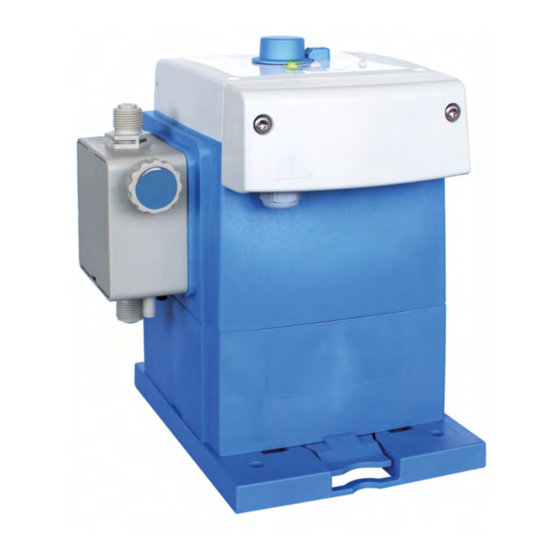
Description of the pump Description of the pump Fig. 3: Construction ‘EcoPro’ Operator panel Mains cable bushing / mains power supply Rotary operating device Suction connection / suction valve Pressure connection / pressure valve Position of type plate Pump head Identification of the pump - Type plates The pump is equipped with a type plate which provides the pump-specific data for identification. -
Page 27: Connection Sockets / Cable Bushings
Description of the pump Connection sockets / cable bushings A screw coupling (M12 x 1.5) is supplied with the pump (Fig. 5, 3) for the cable connection of the enable signal. Fig. 5: EcoPro connections ‘’ Mains cable bushing / Mains connection Screw coupling (M12 x 1.5) Cable bushing for connection: Enable signal Permissible external diameters for connecting the inputs/outputs:... -
Page 28: Pump Head Variants
Description of the pump Pump head variants The litre capacity of the pump is defined depending on the design of the pump head and of the metering valves. NOTICE! Tightening torques of the metering head screws are given on an adhesive label on the corresponding metering head and must always be observed. -
Page 29: Assembly, Installation, Modification And Upgrades
Assembly, installation, modification and upgrades Assembly, installation, modification and upgrades Personnel: Manufacturer Mechanic Service personnel Specialist General information and safety NOTICE! General instructions for installation and assembly: – The pump must be installed at an easily accessible, frost-protected location. – The ambient conditions given in the "Technical data" must be observed. –... - Page 30 Assembly, installation, modification and upgrades Risk due to electrical energy DANGER! Risk of fatal injury from electric current! Contact with live parts represents immediate danger to life due to electrocution. Damage to the insulation or individual components can be life-threatening. –...
-
Page 31: Assembly Variants
Assembly, installation, modification and upgrades Assembly variants Fig. 7: Stand mounting (pos. 1) and wall mounting (pos. 2) The pump can be mounted using the mounting plate both upright (e.g. on a bracket or on the metering container, pos. 1), and on a wall (suspended, pos. 2). For further variable use, the operating part of the pump can be turned to produce variable connection variants. -
Page 32: Stand Mounting Or Floor Mounting
Assembly, installation, modification and upgrades 6.2.1 Stand mounting or floor mounting Fig. 8: Preparations for stand mounting Turn mounting plate over Only use fastening elements with the code 1 (Fig. 8, 2) for stand mounting. Insert fastening elements from the rear into the four openings marked "table" (= stand mounting) and secure them. -
Page 33: Wall Mounting
Assembly, installation, modification and upgrades 6.2.2 Wall mounting Fig. 9: Preparations for wall mounting Turn mounting plate over. Use fastening elements with the code 2 (Fig. 9, 3) and the code 1 (Fig. 9, 2) for wall mounting. Insert fastening elements (labelled: 1, Fig. 9, 2) into the two upper openings marked "wall"... -
Page 34: Installation
Assembly, installation, modification and upgrades Installation Some of the graphics shown in this chapter are schematic diagrams which are intended to represent the general installation. The installation examples and applications shown here are of a functional nature. They provide an overview of correct forms of installation, or approaches to be avoided, in order to ensure that it works properly. -
Page 35: Installation Examples
Assembly, installation, modification and upgrades 6.3.2 Installation examples Hydraulic installation With media that tend towards sedimentation, the base suction valve or the foot valve of the suction line or suction lance must be mounted above the expected sludge layer. Term definition Siphoning Siphoning refers to the maximum fluid level (in this case the supply container) being higher than the lowest point in the metering line. - Page 36 Assembly, installation, modification and upgrades Installation example 3 1 Injection valve / metering valve 2 External release 3 Solenoid valve 4 Pressure control valve When metering in pipes with a vacuum, a pressure control valve (pos. 4) is to be installed in the metering line. A pressure-retention valve or metering valve is not a shut-off device which is absolutely tight sealing.
-
Page 37: Connection Of The Suction And Pressure Lines (Dosing Lines)
Assembly, installation, modification and upgrades Installation example 6 The suction line must always be installed sloping upwards towards the metering pump. Installation example 7 A metering monitoring instrument, such as an oval gear motor (pos. 1), or flow monitor, must be installed into the metering line downstream of the overflow valve and upstream of a pressure control valve or metering valve. -
Page 38: 6.3.3.1 Pipe And Hose Connection With Integrated Support Sleeve
Assembly, installation, modification and upgrades 6.3.3.1 Pipe and hose connection with integrated support sleeve Fig. 10: Pipe and hose connection with integrated support sleeve Pipe or hose connection O-ring Union nut Suction valve, pressure valve Clamping ring A1 Pipe or hose attached Slip-on bushing A2 Target state after assembly Female connector... -
Page 39: 6.3.3.2 Pipe And Hose Connection With Tapered Part
Assembly, installation, modification and upgrades 6.3.3.2 Pipe and hose connection with tapered part Fig. 11: Pipe/hose connection with tapered part Hose O-ring Union nut Suction valve, pressure valve Clamping piece A1 Pipe or hose attached Tapered part B1 Valve connection: Target state after assembly Cut hose (1) straight. -
Page 40: 6.3.3.3 Pipe And Hose Connection With Attachment Nipple And Hose Clamp
Assembly, installation, modification and upgrades 6.3.3.3 Pipe and hose connection with attachment nipple and hose clamp Fig. 12: Pipe and hose connection with attachment nipple and hose clamp Detail/Section: Illustration of individual part Suction valve, pressure valve Hose Hose clamp Union nut A1 Pipe or hose attached Tapered part... -
Page 41: 6.3.3.4 Pipe And Hose Connection With Female Coupling
Assembly, installation, modification and upgrades 6.3.3.4 Pipe and hose connection with female coupling Fig. 13: Pipe and hose connection with female coupling Weld-on connection Suction valve, pressure valve Pipe or hose A1 Pipe or hose in the weld-on connection Union nut B1 Valve connection: Target state after assembly O-ring Place the O-ring (4) in the groove of the suction or pressure valve (5). -
Page 42: Electrical Installation
Assembly, installation, modification and upgrades 6.3.4 Electrical Installation Personnel: Qualified electrician To allow the connection of a cable for pulse control, a M 12 x 1.5 screw coupling is included with the pump. The mains cable is already installed at the factory. Fig. -
Page 43: 6.3.4.1 Terminal Assignment - External Enable Signal
Assembly, installation, modification and upgrades 6.3.4.1 Terminal assignment - External enable signal The terminals are accessible after dismantling the front cover, (see Ä Chapter 6.3.4 ‘Electrical Installation’ on page 42, Fig. 14, 2). In accordance with the terminal assignment given below, modifications can be made to control inputs at the customer's site. -
Page 44: Start-Up
Start-up Start-up Personnel: Manufacturer Production supervisor Service personnel Specialist Operator DANGER! – Initial start-up may only be performed by authorised personnel with experience of metering system operation. – Initial start-up must be documented and the settings made recorded in the log. -
Page 45: Initial Start-Up Of The 'Ecopro
Start-up Electrical dangers DANGER! Electrical hazards are marked by the symbol opposite. Work in these areas may only be carried out by trained personnel with the appropriate authorisation. Initial start-up of the ‘EcoPro’ The enabled viscosity (high or low) is indicated by an LED display when the pump is switched on. -
Page 46: Auto Start Function
Start-up Auto start function DANGER! Danger of automatic start of the pump The the pump is automatically started by connecting the power supply already, without having to press a switch / button before. For security reasons the [auto start] function is not activated when the pump is delivered. -
Page 47: Terminal Assignment 'External Enable"' 'Ecopro
Start-up Terminal assignment ‘external enable"’ ‘EcoPro’ The ‘EcoPro’ can be connected to a customer control unit, such as a PLC controller (terminals 8 (GND) and 9 (enable signal)). Fig. 17: External enable 417102264 Rev. 5-01.2019... -
Page 48: Calibration On Initial Start-Up
Start-up Calibration on initial start-up The specified metering capacities in metering pumps are always determined under ideal conditions (metering of water at 20 °C, short suction and metering pipes, rated back- pressure, no pressure-boosting valves in the metering line). As these conditions never occur in the field, you are advised to calibrate the actual metering rate of the metering pump under the prevailing conditions on-site. -
Page 49: Operation
Operation Operation Personnel: Production supervisor Operator Specialist Switching the pump on and off Fig. 18: Switching the EcoPro on/off ‘’ Rotary button for stroke adjustment LED - When the pump is started: green (standby) Locking mechanism for fixing the rotary button in place LED - Dosing mode "high", colour: flashing yellow LED - Alarm signal, colour: red flashing ‘ON/OFF button’... -
Page 50: Setting Of The Capacity / Flow Rate
Operation Setting of the capacity / flow rate The stepper motor technology means that both the suction stroke duration and metering stroke duration can be set separately during operation via the stroke adjustment (Fig. 18, pos. 1). Fig. 19: Time distribution (t) of the suction (s) and metering stroke (p) at a metering rate setting of 100, 50 and 25% Use the ‘rotary button for stroke adjustment’... -
Page 51: Changing A Container - Empty Signal
Operation Changing a container - Empty signal Chemical hazards (dosing medium/active substance) DANGER! Risk of injury to the skin and eyes caused by the chemical used (dosing medium). – Read the enclosed safety data sheet carefully before using the dosing medium. -
Page 52: Maintenance
Maintenance Maintenance Personnel: Mechanic Qualified electrician Service personnel The wearing and spare parts belonging to the pump type can be identified on the basis of the pump key. Ä Chapter 13.3 ‘ ‘EcoPro’ pump key’ on page 75) can be The pump key ( Ä... -
Page 53: Service Position
Maintenance Service position Before maintenance work is permitted to be performed on the pump, the pump should be changed to maintenance mode! The causes the motor and the diaphragm to be reset, simplifying the maintenance work! Putting the pump in the service position: [Pressing the ON/OFF] and [test] buttons simultaneously. -
Page 54: Maintenance Table
Maintenance Maintenance table Interval Maintenance work Personnel 24 hours after Checking the metering head screws Mechanic commissioning or The tightening torques of the metering head screws are metering head attached to the pump heads using adhesive labels. In servicing Ä Chapter 9.4 ‘Installing addition, these are specified in the the dosing valve in the correct position’... -
Page 55: Replace The Suction / Pressure Valve And Metering Cartridge
Maintenance Replace the suction / pressure valve and metering cartridge Fig. 20: Replace the suction / pressure valve and metering cartridge O-ring, hose connection, pressure side O-ring: Pump head suction valve Pressure valve Suction valve O-ring: Pump head pressure valve O-ring, hose connection, suction-side V3 metering cartridge Remove suction and pressure valve using an open spanner. -
Page 56: Installing The Dosing Valve In The Correct Position
Maintenance Installing the dosing valve in the correct position WARNING! When installing the valves, ensure that the flow direction is correct. The direction of flow is marked by an impressed arrow on the suction/ pressure valves. NOTICE! It is essential that the tightening torques given below are observed, firstly to ensure the leak-tightness of the system and secondly to ensure the integrity of the thread. -
Page 57: Replacing The Pump Head And Diaphragm
Maintenance Replacing the pump head and diaphragm CAUTION! Diaphragm: – Before changing the diaphragm, it is essential to change the pump to servicing mode. Ä Chapter 9.1 ‘Service position’ on page 53 – Only tighten diaphragms by hand and do not use any tools! The service life of the diaphragm depends on the following: –... -
Page 58: Pump Head Size 5 L/H And 11 L/H
Maintenance Pump head size 5 l/h and 11 l/h Fig. 21: Replacing the pump head and diaphragm Adhesive label: Tightening torque of metering head Diaphragm screws Intermediate plate Cover plate Protective diaphragms Metering head screws (4 off) Vent screw Pump head Note the following points during assembly: –... -
Page 59: Pump Head Size 30 L/H And 50 L/H
Maintenance Pump head size 30 l/h and 50 l/h Fig. 22: Replacing the pump head and diaphragm Adhesive label: Tightening torque of metering head 4b Intermediate plate with sensor screws Protective diaphragms Metering head screws (4 off) 6a Diaphragm extension for intermediate plate without Pump head sensor Diaphragm... -
Page 60: Pump Head Size 120 L/H
Maintenance Pump head size 120 l/h Fig. 23: Replacing the pump head and diaphragm Adhesive label: Tightening torque of metering head Retaining bolts for the adapter plate (x4) screws 6a Adapter plate without sensor Metering head screws (4 off) 6b Adapter plate with sensor Pump head Diaphragm extension Diaphragm... -
Page 61: Consumables And Spare Parts
Consumables and spare parts Consumables and spare parts NOTICE! Material damage by using incorrect tools! Material damage may arise by using incorrect tools during assembly, maintenance or troubleshooting. Only use the correct tools. CAUTION! Independent conversions or changes are only permissible following consultation and with the approval of the manufacturer. -
Page 62: Set Of Wearing Parts 30 L/H, 50 L/H And 120 L/H
Consumables and spare parts 10.1.2 Set of wearing parts 30 l/h, 50 l/h and 120 l/h 1 x suction valve 1 x diaphragm 1 x Pressure valve 1 x protective diaphragm Pump capacity Order code for wearing parts set: Article no. EBS-no. - Page 63 Consumables and spare parts Replacement part module: Cover - ‘EcoPro control part’ Fig. 25: Replacement part module: Display Cover - EcoAdd control unit ‘’ Pos. Designation Article No. EBS No. (4 x) screw, 35 x 30 WN5451 V2A 413070100 On request (1 x) screw, 35 x 10 WN5451 V2A TX 413070094 On request...
-
Page 64: Pump Heads
Consumables and spare parts 10.2.2 Pump heads 10.2.2.1 Replacement part module: Pump head 5 l/h Fig. 26: Replacement part module: Pump head 5 l/h Pos. Designation Article No. EBS No. Adhesive label for commissioning / tightening torque (4 Nm) 34800327 On request Cover plate PP pebble grey 35200180... -
Page 65: 10.2.2.2 Replacement Part Module: Pump Head 11 L/H
Consumables and spare parts 10.2.2.2 Replacement part module: Pump head 11 l/h Fig. 27: Replacement part module: Pump head 11 l/h Pos. Designation Article No. EBS No. Adhesive label for commissioning / tightening torque (4 Nm) 34800327 On request Cover plate PP pebble grey 35200180 On request Cover plate PVDF natural... -
Page 66: 10.2.2.3 Replacement Part Module: Pump Head 30 L/H And 50 L/H
Consumables and spare parts 10.2.2.3 Replacement part module: Pump head 30 l/h and 50 l/h Fig. 28: Replacement part module: Pump head 30 l/h and 50 l/h Pos. Designation Article No. EBS No. Adhesive label for commissioning / tightening torque (6 Nm) 34900291 On request Hexagon socket screw, M 6 x 90, DIN 912, V2A... -
Page 67: 10.2.2.4 Replacement Part Module: Pump Head 120 L/H
Consumables and spare parts 10.2.2.4 Replacement part module: Pump head 120 l/h Fig. 29: Replacement part module: Pump head 120 l/h Pos. Designation Article No. EBS No. Adhesive label for commissioning / tightening torque (6 Nm) 34900291 On request Hexagon socket screw, M 6 x 90, DIN 912, V2A 413031148 On request Washer, 17 x 6.4 x 3 DIN 7349 V2A... -
Page 68: Repair, Conversion, Upgrade
Repair, conversion, upgrade Repair, conversion, upgrade Personnel: Qualified electrician Service personnel Specialist DANGER! Risk due to electrical energy Work on electrical components should only be performed by qualified electrical engineers or specially trained expert personnel. Risk of fatal injury from electric current! Contact with live parts represents immediate danger to life due to electrocution. -
Page 69: Modification/Upgrade
Repair, conversion, upgrade 11.2 Modification/upgrade 11.2.1 Modification - turning the pump head To allow the pump to be adjusted to the site conditions, it is possible to turn the grey control unit (operating unit/upper part of the pump). DANGER! Risk of electric shock Pay attention to disconnect the power supply immediately and to secure against accidental switch-on! Fig. -
Page 70: Modification - Change From Stand Mounting To Wall Mounting
Repair, conversion, upgrade 11.2.2 Modification - change from stand mounting to wall mounting To allow the pump to be adjusted to the site conditions, you can use the pump in either stand-mounted or wall-mounted form. Fig. 31: Changing stand mounting (upright, e.g., floor, bracket or canister) for wall mounting (suspended) If necessary, dismantle the connecting lines (hydraulic and electric). -
Page 71: Upgrading - From 'Ecopro' To 'Ecoadd
Repair, conversion, upgrade 11.2.3 Upgrading - From ‘EcoPro’ to ‘EcoAdd’ The ‘EcoPro’ version of the pump can be converted or upgraded to the ‘EcoAdd’ version with an operating display and Bluetooth interface by replacing the control unit. Fig. 32: / Upgrading the ‘EcoPro’ to the ‘EcoAdd version’ Undo the fastening screws on the control unit of the ‘EcoPro’... -
Page 72: Operational Malfunctions / Troubleshooting
Operational malfunctions / troubleshooting Operational malfunctions / troubleshooting Personnel: Production supervisor Operator Qualified electrician Mechanic NOTICE! Damage caused by using incorrect tools! Damage may occur as a result of using incorrect tools during assembly, maintenance or troubleshooting. Only use the correct tools. DANGER! –... -
Page 73: General Troubleshooting And Fault Rectification
Operational malfunctions / troubleshooting 12.1 General troubleshooting and fault rectification NOTICE! With some error messages the pump should always be sent to the customer service department as it is only possible to access the level of the control to which these messages relate. Ä... -
Page 74: Technical Specifications
Technical specifications Technical specifications 13.1 Packaging Data Value Unit Packaging size (L x W x H) 395 x 290 x 360 mm Weight (depending on pump design) 3,5 - 6 Kg Due to the low weight, no special lifting gear is required during transport. ENVIRONMENT! Risk of environmental damage due to incorrect disposal! Packaging materials are valuable raw materials and can, in many cases, be... -
Page 75: Ecopro' Pump Key
Technical specifications 13.3 ‘EcoPro’ pump key The pump key comprises four groups: Group I: Control unit: Ä Chapter 13.3.1 ‘Pump key group I’ on page 75 Group II: Pump head: Ä Chapter 13.3.2 ‘Pump key group II’ on page 76 Group III: Housing/driver unit: Ä... -
Page 76: Pump Key Group Ii
Technical specifications 13.3.2 Pump key group II "Pump head" [01110S|D|F|C|0|0|S] Pos. 4: ‘Capacity in L/back-pressure/driver unit’ Key: Capacity in L: [l/h] Pressure [MPa (bar)] Size of driver unit 00510X 0,05 - 5 1 (10) 01110S 0,11 - 11 1 (10) 03003S 0,3 - 30 0,3 (3) -
Page 77: General Data
Technical specifications 13.4 General data Type Type Type Type Type Name 00510X 01110S 03003M 05010M 12003M Metering mode [low] Max. metering capacity [l/h] Metering mode 33.3 [high] Min. metering capacity [l/h] 0.05 0.11 0.30 0.50 Max. metering back-pressure [MPa (bar)] 0.1 (10) 0.03 (3) 0.1 (10) -
Page 78: Electrical Data
Technical specifications 13.5 Electrical data Type Type Type Type Type Name 00510X 01110S 03003M 05010M 12003M Supply voltage [V / Hz] 100 - 240 ±10% / 50/60 Motor power [W] Degree of protection IP65 Appliance class Level, external release, batch max. -
Page 79: Materials
Technical specifications 13.7 Materials Enclosure: PPO (Noryl) Metering head: PP, optionally PVDF, stainless steel 1.4571 Diaphragm: PTFE - EPDM composite diaphragm Seals: FKM or EPDM, either PTFE or FFPM (Kalrez) Valve balls: Ceramic, either PTFE or stainless steel 1.4401 Valve springs: Hastelloy C4 Colour: Blue RAL 5007... -
Page 80: Ecopro Metering Pump
Technical specifications 13.8.2 EcoPro metering pump Fig. 35: Dimensions ‘EcoPro’ 13.9 Metering capacity diagrams/flow rates 13.9.1 Flow rate: 5 l/h, metering back-pressure: 1 MPa (10 bar) DV Metering volume [l/h] DP Metering back-pressure [bar] 417102264 Rev. 5-01.2019... -
Page 81: Flow Rate: 11 L/H, Metering Back-Pressure: 1 Mpa (10 Bar)
Technical specifications 13.9.2 Flow rate: 11 l/h, metering back-pressure: 1 MPa (10 bar) DV Metering volume [l/h] DP Metering back-pressure [bar] 13.9.3 Flow rate: 30 l/h, metering back-pressure: 0.3 MPa (3 bar) DV Metering volume [l/h] DP Metering back-pressure [bar] 417102264 Rev. -
Page 82: Flow Rate: 50 L/H, Metering Back-Pressure: 1 Mpa (10 Bar)
Technical specifications 13.9.4 Flow rate: 50 l/h, metering back-pressure: 1 MPa (10 bar) DV Metering volume [l/h] DP Metering back-pressure [bar] 13.9.5 Flow rate 120 l/h, metering back-pressure: 0.3 MPa (3 bar) DV Metering volume [l/h] DP Metering back-pressure [bar] 417102264 Rev. -
Page 83: Decommissioning / Dismantling / Environmental Protection
Decommissioning / dismantling / environmental protection Decommissioning / dismantling / environmental protection Personnel: Manufacturer Production supervisor Operator Qualified electrician Mechanic DANGER! Risk of injury due to the disregard of the specified personal protective equipment (PPE)! For all disassembly work, please respect the use of the PSA which is specified on the product data sheet. -
Page 84: Dismantling
Decommissioning / dismantling / environmental protection 14.2 Dismantling DANGER! Dismantling may only be carried out by skilled personnel using PPE. Before commencing dismantling, ensure that the device has been fully isolated from the power supply. Contact with live components can be fatal. Activated electrical components can make uncontrolled movements and lead to serious injury. -
Page 85: Disposal And Environmental Protection
Decommissioning / dismantling / environmental protection 14.3 Disposal and environmental protection ENVIRONMENT! Risk of environmental damage due to incorrect disposal! Incorrect disposal can be a threat to the environment. – Electrical scrap, electronic components, lubricants and other operating fluids must be disposed of by approved waste disposal service providers –... -
Page 86: Ec Declaration/Declaration Of Conformity
Declaration ’ may change. The latest ‘Declaration of Conformity / CE Declaration’ will therefore be published on the internet: To download the instructions, please use the link below or scan the QR code. http://www.ecolab-engineering.de/fileadmin/download/ bedienungsanleitungen/ce-konformitaetserklaerung/CE/ CE_EcoPro_EcoAdd.pdf Fig. 36: EC Declaration/Declaration of Conformity... -
Page 87: Index
Index Index Android App Hydraulic installation Download ......6 Installation example 1 ....35 Installation example 2 . - Page 88 Index Mounting plate Results of the operating steps Use in pump series ....79 Representation method ....8 Multi-function valve .
- Page 89 Index on the packaging ..... 10 Type plate ......74 Technical specifications Use .
- Page 90 / revision: Letze Änderung: 08.01.2019 last changing: Copyright Ecolab Engineering GmbH, 2019 Alle Rechte vorbehalten All rights reserved Nachdruck, auch auszugsweise, nur mit Genehmigung der Firma Ecolab Engineering GmbH Reproduction, also in part, only with permission of Ecolab Engineering GmbH...
Need help?
Do you have a question about the EcoPro-ES-00510X-PFC-00S-1S-S0 and is the answer not in the manual?
Questions and answers