
Related Manuals for Allwin21 AccuThermo AW810M


Summary of Contents for Allwin21 AccuThermo AW810M
- Page 1 Allwin21 Corporation AccuThermo® AW810M Rapid Thermal Process System Technical Manual Allwin21 Corporation 220 Cochrane Circle, Morgan Hill CA 95037 www.allwin21.com...
- Page 2 A9-0716-01 rev. C AccuThermo® AW810M Technical Manual ALLWIN21 ACCUTHERMO® AW810M RAPID THERMAL PROCESS SYSTEM TECHNICAL MANUAL Allwin21 Corporation 220 Cochrane Circle Morgan Hill, CA 95037...
-
Page 3: Service Information
Allwin21 Corporation. Statement of Confidentiality The information contained herein is confidential to and the property of Allwin21 Corporation. It may not be reproduced nor disclosed in whole or in part by any method without the prior written permission of Allwin21 Corporation. -
Page 4: Warranty
Allwin21 Corporation liability to the customer or anyone claiming through or on behalf of the customer with respect to any claim or loss arising out of the purchase and/or sale of any Allwin21 Corporation product shall be limited to the original purchase price amount of the product. In no event shall Allwin21... - Page 5 In order to honor a warranty for any Allwin21 system, the customer is required to perform the recommended preventive maintenance (PM) on the system. Allwin21 Corporation will perform PM training during system start-up.
-
Page 6: Preface
A9-0716-01 rev. C AccuThermo® AW810M Technical Manual PREFACE INTENDED AUDIENCE This manual has been written for technicians and process development engineers working with the AccuThermo® AW810M Rapid Thermal Processing (RTP) System. It provides an overview of the system operation and maintenance procedures, as well as a troubleshooting guide. Please read this manual carefully before operating the AccuThermo®... -
Page 7: Table Of Contents
Installation ..................... 17 3.1 Purchaser’s Responsibility ....................17 3.2 Allwin21 Service ........................ 17 3.2.1 Field Service Installation ..................17 3.2.2 Training ........................ 17 3.3 Installation Process Overview .................... 18 3.3.1 Installation Procedures ..................18 3.3.2 Required Tools ..................... 19 ... - Page 8 A9-0716-01 rev. C AccuThermo® AW810M Technical Manual 3.4.7 Electrical ......................25 3.4.8 Cooling Air ......................31 3.4.9 Chamber Cooling Water ..................33 3.4.10 Process Gas ......................37 3.4.11 Process Exhaust ....................39 3.4.12 Pneumatic Air ....................40 3.4.13 Cabinet Exhaust ....................41 3.4.14 ...
- Page 9 A9-0716-01 rev. C AccuThermo® AW810M Technical Manual 6.4 Optimizing the Temperature Profile ................. 106 6.4.1 Recipe Parameters ....................106 6.4.2 Recipe Lamp Zone Control ................111 6.4.3 Temperature Profile Stages ................113 6.4.4 Temperature Profile Optimization ..............115 6.4.5 Temperature Curves ................... 120 6.4.6 ...
- Page 10 A9-0716-01 rev. C AccuThermo® AW810M Technical Manual Maintenance & Diagnostics ............... 175 9.1 Overview .......................... 175 9.2 Preventative Maintenance (PM) Schedule ............... 177 9.2.1 Daily Maintenance ..................... 177 9.2.2 Weekly Maintenance ..................178 9.2.3 Monthly Maintenance ..................179 9.2.4 ...
- Page 11 A9-0716-01 rev. C AccuThermo® AW810M Technical Manual Troubleshooting ..................271 10.1 Overview .......................... 271 10.1.1 Tips for troubleshooting ................... 272 Rules for Equipment Maintenance ................. 272 Experiences for Equipment Troubleshooting ..............272 10.1.2 Testing Fuses ....................274 10.1.3 PCB Connectors ....................276 10.1.4 ...
- Page 12 A9-0716-01 rev. C AccuThermo® AW810M Technical Manual 10.19 Main Power ........................326 10.20 Overheat ........................... 327 10.21 Process ..........................329 10.21.1 Process Results Indicate Different Temperature, Thermocouple ....330 10.21.2 Process Results Indicate Different Temperature, Pyrometer ......330 10.21.3 Process Temperature is Different than before to get same result ....330 10.22 ...
- Page 13 A9-0716-01 rev. C AccuThermo® AW810M Technical Manual C: Copying Process Data ....................... 396 D: Keyboard Shortcuts ......................398 E: Updating the Control Software ..................399 F: Backing Up and Restoring the Software ................401 G: Software Startup ....................... 406 H: Selection of the Purity of Gases ..................
-
Page 14: List Of Figures
Figure 1-1: AccuThermo AW810M system ................1 Figure 3-1: AW810 Footprint and Elevation ................20 Figure 3-2: AccuThermo AW810M System Rear Utility Panel Connections ......21 Figure 3-3: Gas Pressure and Flow Rate Relationship for Different Tube Diameters ....23 ... - Page 15 A9-0716-01 rev. C AccuThermo® AW810M Technical Manual Figure 8-5: Extended Range Pyrometer ................... 163 Figure 8-6: ERP and Thermocouple Temperature Measurements ........... 164 Figure 8-7: Recipe with preheat step ..................172 Figure 8-8: Multi-step recipe to check stability ............... 173 Figure 9-1: ...
- Page 16 A9-0716-01 rev. C AccuThermo® AW810M Technical Manual PAGE INTENTIONALLY LEFT BLANK...
-
Page 17: Introduction
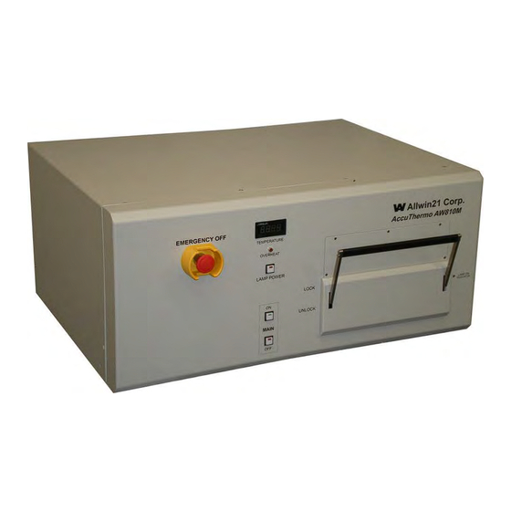
The AccuThermo® RTP system, figure 1-1, consists of a chamber unit and a computer running the Allwin21 control software. The wafer to be processed is placed on a quartz tray that slides into a quartz isolation tube in the chamber. Two banks of lamps, one above the quartz tube and... -
Page 18: Features
A9-0716-01 rev. C AccuThermo® AW810M Technical Manual one below it, provide the source of energy for heating the wafer. The lamps can be controlled manually and automatically from the computer. The control software allows full control and diagnostics of the AccuThermo® RTP system. In addition, it allows the creation of recipes for automated control of the temperature and, optionally, process gas flow. - Page 19 A9-0716-01 rev. C AccuThermo® AW810M Technical Manual APPLICATIONS The AccuThermo® RTP system is a versatile tool that is useful for many applications: Ion Implant Activation Polysilicon Annealing Oxide Reflow Silicide Formation Contact Alloying Oxidation and Nitridation ...
-
Page 20: System Process Specifications
A9-0716-01 rev. C AccuThermo® AW810M Technical Manual SYSTEM PROCESS SPECIFICATIONS Following are the specifications for the AccuThermo Rapid Thermal Processor (RTP) system. Wafer handling: Manual loading of wafer into the chamber, single wafer processing. Wafer sizes: 4", 5", 6" and 8” wafers. ... - Page 21 A9-0716-01 rev. C AccuThermo® AW810M Technical Manual PAGE INTENTIONALLY LEFT BLANK...
- Page 22 A9-0716-01 rev. C AccuThermo® AW810M Technical Manual PAGE INTENTIONALLY LEFT BLANK...
-
Page 23: Safety Precautions
WARNING Only ALLWIN21 or qualified personnel should install, start up, operate and/or repair the AccuThermo® RTP system. Damage to the system or injury to personnel could result if the preceding actions are carried out by unqualified personnel. -
Page 24: Notes, Cautions And Warnings
A9-0716-01 rev. C AccuThermo® AW810M Technical Manual NOTES, CAUTIONS AND WARNINGS When operating and maintaining the AccuThermo® RTP system, the following safety procedures and precautions must be followed to avoid certain hazards. Observe all warnings and cautions. Their purpose is to protect personnel from injury and long term health hazards and to protect the machine from damage. -
Page 25: Safety Features
A9-0716-01 rev. C AccuThermo® AW810M Technical Manual SAFETY FEATURES There is a watchdog timer on the AccuThermo® RTP system control board that will shut off the lamps if the software or computer freezes. Chamber Door Interlock Switch: This interlock detects if the chamber door is closed. If the chamber door is not closed, then the heating source will not come on. -
Page 26: Utilities Inspection
A9-0716-01 rev. C AccuThermo® AW810M Technical Manual 2.4 UTILITIES INSPECTION Inspect the system utility connections and sources before switching on the AW810M. Visually inspect the following utilities to make sure connections are secure: Electrical power. Gas-handling inlets. Cooling water inlet and outlet for chamber cooling ... -
Page 27: System Operation
2.6 MAINTENANCE During the maintenance operation, observe the following precautions: Do not use replacement parts not provided or recommended by Allwin21. WARNING Allwin21 is not liable for any damage or injury which may occur when unauthorized parts are used. -
Page 28: Gas Handling
), argon (Ar), Forming Gas, oxygen (O ) and helium (He). CAUTION Allwin21 Corp. is not liable for the use of gases not recommended by the factory. Make sure the specified gases are connected to the proper inlets on the rear panel. ... -
Page 29: Hazards
Safety interlocks are installed to shut off electrical power to the system when the cover is removed. Only qualified troubleshooting maintenance technicians should be permitted to work on an uncovered AccuThermo® RTP system. Allwin21 assumes no liability for injuries or deaths caused by operation with interlocking devices defeated. Caution and safety measures characteristically taken with AC and DC circuitry are imperative. -
Page 30: Process Byproduct Hazards
Solvent-proof neoprene or viton gloves should be worn while maintaining the chamber surfaces and its accessories. Allwin21 Corp. claims no responsibility for the safety of the byproducts of the AccuThermo Rapid Thermal Processor system. 2.8.4... -
Page 31: Thermal Hazards
A9-0716-01 rev. C AccuThermo® AW810M Technical Manual 2.8.5 THERMAL HAZARDS The quartz tray and isolation tube must be allowed to cool down before they are serviced. Allow 20 to 30 minutes for the quartzware to cool before touching. Burns may result if the quartzware is touched before the cooling time elapses. - Page 32 A9-0716-01 rev. C AccuThermo® AW810M Technical Manual PAGE INTENTIONALLY LEFT BLANK...
-
Page 33: Installation
The Allwin21Field Service Engineer will verify correct installation and system operation. The following is an overview of the activities the Allwin21 Field Service Engineer will carry out. 1) Conduct a thorough visual inspection of the system. -
Page 34: Installation Process Overview
Install and connect the computer to the AccuThermo® RTP system. If it is desired to have an Allwin21 Field Service help in the installation of the AccuThermo® RTP system, then they will do the following steps. Otherwise, the purchaser must do them. -
Page 35: Required Tools
A9-0716-01 rev. C AccuThermo® AW810M Technical Manual 3.3.2 REQUIRED TOOLS You need the following tools to install your AccuThermo® RTP system: Allen wrench set (SAE) Screwdriver set Open-end wrenches (SAE) Latex gloves Test wafers K-Type thermocouple that matches the process wafer configuration... -
Page 36: Installation Site Requirements
3.4.2 SPACE REQUIREMENTS The dimensions of the AllWin21 AccuThermo AW810M System are 16" H x 34" W x 30.5" D (figure 3-1). Figure 3-1: AW810 Footprint and Elevation The AllWin21 AccuThermo® RTP system should be placed on top of a work bench. Space must be made available on the work surface next to the chamber for a mid-size desktop computer (PC), computer LCD monitor, keyboard, and mouse. -
Page 37: Utility Connections
Finally, while chamber-cooling water can be provided to the AccuThermo® RTP chamber from the facility supply, AllWin21 recommends use of a chamber heat exchanger. Typically, a low capacity heat exchanger unit is installed near the chamber. If this option is selected, sufficient additional space near the AccuThermo®... -
Page 38: Adequate Cooling
A9-0716-01 rev. C AccuThermo® AW810M Technical Manual 3.4.4 ADEQUATE COOLING The heating chamber incorporates three cooling subsystems: A water cooling system for the chamber walls and door. A nitrogen or air cooling system to reduce residual heating of the quartz window and lamps. -
Page 39: Proper Tubing Size
A9-0716-01 rev. C AccuThermo® AW810M Technical Manual 3.4.5 PROPER TUBING SIZE Adequate gas, air and water flow is essential to the proper operation of the system. If the tubing inner diameter is too small, the flow rate can be reduced. If the tubing is too long, the flow rate can also be reduced. -
Page 40: Air Conditioning
A9-0716-01 rev. C AccuThermo® AW810M Technical Manual 3.4.6 AIR CONDITIONING The moisture in the ambient air around the AW810M should not condense on any part of the system. Air Condition Requirements AIR CONDITION Temperature: 20-30°C Humidity: Non-condensing... -
Page 41: Electrical
AccuThermo® AW810M Technical Manual 3.4.7 ELECTRICAL REQUIREMENTS Power requirements vary between the United States, Europe and Japan. Specifications for each are shown in the tables below. AccuThermo AW810M Power Requirements voltage: 208 VAC # phases: 3-phase # wires: 3 supply, 1 neutral, and 1 ground... -
Page 42: Figure 3-1: Recommended Accuthermo® Rtp System Power Distribution Diagram
A9-0716-01 rev. C AccuThermo® AW810M Technical Manual AC POWER DISTRIBUTION The AccuThermo® RTP systems are capable of heating single wafers very rapidly. This capability means that the AccuThermo® RTP system has very high instantaneous current demands. Therefore, special care must be taken in connecting the AC power from the facility main AC lines to the AccuThermo®... - Page 43 A9-0716-01 rev. C AccuThermo® AW810M Technical Manual The following guidelines should be followed when you connect the AccuThermo® RTP system power in order to ensure proper system operation: Put the AccuThermo® RTP system on a separate power distribution box from other equipment, preferably with its own power transformer.
-
Page 44: Figure 3-2: 3-Phase Ac Power Connections With Circuit Breaker
A9-0716-01 rev. C AccuThermo® AW810M Technical Manual ELECTRICAL CONNECTIONS Once the facility AC power and other facility connections have been routed to the AccuThermo® RTP system, use the following procedures and the appropriate figures for connecting the AC power to the system. There are two different methods to connect the power cables to the AccuThermo®... - Page 45 A9-0716-01 rev. C AccuThermo® AW810M Technical Manual USA/European Electrical Connections Figure 3-6: USA/Europe (208/380 VAC) Electrical Connections Follow the following procedure for connecting to USA and European power, and refer to figures 3-5 and 3-6. Step 1. Remove the top cover from the AccuThermo® RTP system. Refer to the Maintenance section “Chamber Unit Cabinet Cover Removal”.
-
Page 46: Figure 3-4: Japanese (200 Vac) Electrical Connections
A9-0716-01 rev. C AccuThermo® AW810M Technical Manual Japanese Electrical Connections Figure 3-7: Japanese (200 VAC) Electrical Connections Follow the following procedure for connecting to Japanese power, and refer to figures 3-5 and 3-7. Step 1. Remove the top cover from the AccuThermo® RTP system. Refer to the Maintenance section “Chamber Unit Cabinet Cover Removal”. -
Page 47: Cooling Air
A9-0716-01 rev. C AccuThermo® AW810M Technical Manual 3.4.8 COOLING AIR When the AccuThermo® is in use, heat radiating from the lamps and the wafer raises the temperature of the quartz window. During a process, the quartz window heats up, but not as much as if there was no air cooling. -
Page 48: Figure 3-5: Recommended Non-Process Nitrogen Supply/Cda Configuration
A9-0716-01 rev. C AccuThermo® AW810M Technical Manual REQUIREMENTS type Nitrogen (N ) or Clean-Dry-Air (CDA) Quartz oil-and-water-free, filtered to 3 microns Isolation Tube Cooling Air flow rate 20-30 scfm (570-850 slpm) minimum inlet pressure 60 psig (400 kPa) typical fitting 3/8"... -
Page 49: Chamber Cooling Water
A9-0716-01 rev. C AccuThermo® AW810M Technical Manual 3.4.9 CHAMBER COOLING WATER During wafer processing, cooling water flows through the AccuThermo chamber walls to remove excess heat. This helps stabilize the chamber walls so it does not break the quartz isolation tube due to expansion. - Page 50 A9-0716-01 rev. C AccuThermo® AW810M Technical Manual REQUIREMENTS type Distilled Water Chamber pre-filtered with conventional particulate filter to Cooling Water 100 microns (No DI Water) 1-5 mega-ohms resistivity flow rate 3.5 gpm (13 lpm) minimum pressure differential 10 psi (0.7 kg/cm inlet pressure 30 psig (2.11 kg/cm minimum...
-
Page 51: Figure 3-6: Optimal Cooling Water Supply Configuration
A9-0716-01 rev. C AccuThermo® AW810M Technical Manual CONFIGURATION The customer must supply a water filter. The water filter is connected to the water source line of the AccuThermo® RTP system. It is recommended to be 100 micron (nominal). It is used to filter out sediment, dirt and sand. - Page 52 There are 27 lamps and they are rated at 1.5kW each. This means the AccuThermo AW810M has the potential of producing about 40.5kW of heat when full on, but this is never achieved. The removal of excess heat is shared by 2 cooling systems in the AW810M.
-
Page 53: Process Gas
A9-0716-01 rev. C AccuThermo® AW810M Technical Manual 3.4.10 PROCESS GAS REQUIREMENTS type Any inert and/or non-corrosive gas. Process Gases Typically, Nitrogen (N2), oxygen (O2), argon (Ar), and/or helium (He) are used. pressure 15 psig (1.1 kg/cm minimum 20 psig (1.4 kg/cm typical 30 psig (2.1 kg/cm maximum... -
Page 54: Figure 3-7: Optimal Process Gas Supply Configuration
A9-0716-01 rev. C AccuThermo® AW810M Technical Manual Figure 3-10: Optimal Process Gas Supply Configuration NOTE There are no pressurized vessels in this unit. However, the end- user needs to provide connection to such vessels in a safe manner that is compliance with local and industrial regulations. It is the end-user’s responsibility to meet these requirements. -
Page 55: Process Exhaust
A9-0716-01 rev. C AccuThermo® AW810M Technical Manual 3.4.11 PROCESS EXHAUST REQUIREMENTS exhaust back pressure 0.5” water (0.9 mmHg) minimum Process Gas (scrubber draw) Exhaust 0.75” water (1.4 mmHg) typical 1.0" water (1.9 mmHg) maximum fitting 3/8” male Swagelok fitting out to building scrubber system CONFIGURATION The process exhaust, to carry used process gases out of the heating chamber, should be connected... -
Page 56: Pneumatic Air
A9-0716-01 rev. C AccuThermo® AW810M Technical Manual 3.4.12 PNEUMATIC AIR REQUIREMENTS type Clean Dry Air (CDA) or Nitrogen (N2) Compressed oil-and-water-free Pneumatic Actuation Gas 80 psig (550 kPa) 5 psig (35 kPa) Inlet Pressure Valve flow rate Less Than 1 SCFM Typical (optional) fitting 1/4”... -
Page 57: Cabinet Exhaust
A9-0716-01 rev. C AccuThermo® AW810M Technical Manual 3.4.13 CABINET EXHAUST REQUIREMENTS flow rate 100 cfm (3000 lpm) Chamber Cabinet pressure -0.75 “ water Exhaust fitting 4" exhaust vent connected to house exhaust system Gas Box pressure -0.75 “ water Exhaust fitting 4"... -
Page 58: Pyrometer Cooling Water
Please see the chiller’s manual for installation requirements, operation, and maintenance. If there are any problems with the chiller, please contact the manufacturer for help. Allwin21 Corp. can only give you minimum support for the chiller. It is recommended that distilled water be used for cooling the pyrometer. - Page 59 A9-0716-01 rev. C AccuThermo® AW810M Technical Manual PYROMETER COOLING SYSTEM The AccuThermo® RTP system has a separate, closed-loop water system to cool the pyrometer, if one is installed in the system. A water chiller unit, which must be located near the system, circulates water through the pyrometer to maintain a constant pyrometer temperature.
- Page 60 A9-0716-01 rev. C AccuThermo® AW810M Technical Manual Step 5. Monitor the water temperature on the controller’s display. The temperature should stabilize at 20°C within 90 minutes. NOTE Any change in pyrometer cooling water temperature will affect the calibration of the pyrometer. Always verify that the water temperature has stabilized at 20°C prior to running a process cycle.
-
Page 61: Unpacking And Inspecting The System
3.5.1 UNCRATING The AllWin21 AccuThermo® RTP system is shipped in one crate: a heating chamber cabinet, computer, PC monitor, accessories and a chiller for the pyrometer (optional). Unpacking should not take place until the manual is removed and the unpacking instructions are thoroughly understood. -
Page 62: System Inspection
However, if the container shows visible signs of damage upon delivery, notify the carrier immediately. Do not notify Allwin21, as the initial claim for damages must be filed with the carrier. Retain all shipping containers and packing material for damage inspection. -
Page 63: Installing The Computer
A9-0716-01 rev. C AccuThermo® AW810M Technical Manual INSTALLING THE COMPUTER This section describes the procedure for installing the AllWin21 AccuThermo® RTP Graphical User Interface (GUI) computer and connecting this computer system to the AccuThermo Rapid Thermal Processor (RTP) chamber. 3.6.1 OVERVIEW OF THE COMPUTER The AccuThermo®... -
Page 64: Interconnection Of The Computer Assembly
NOTE At least 85% of all problems can be attributed to connectors. At AllWin21 we have these simple rules which we follow. 1) Do not drop connectors. It can bend and damage pins and crack the housing, etc. Treat connectors like “eggs”. Treat PCB like “glass”. -
Page 65: Connecting Computer To Accuthermo® Rtp System
A9-0716-01 rev. C AccuThermo® AW810M Technical Manual 3.6.3 CONNECTING COMPUTER TO ACCUTHERMO® RTP SYSTEM Connecting the computer to your AccuThermo® RTP chamber unit consists of simply connecting the appropriate cables between the computer and the AccuThermo® RTP chamber unit. Step 1. Connect the 25-pin M-M D-sub connector cable between the computer’s “Parallel Port”, and the AccuThermo®... -
Page 66: Installing The Quartz Wafer Tray
A9-0716-01 rev. C AccuThermo® AW810M Technical Manual INSTALLING THE QUARTZ WAFER TRAY The AccuThermo® RTP system uses two major pieces of quartzware. These are the quartz isolation tube and the quartz wafer support tray. The AccuThermo® RTP systems are normally shipped with the quartz isolation tube installed. -
Page 67: Utility Check List
A9-0716-01 rev. C AccuThermo® AW810M Technical Manual UTILITY CHECK LIST ELECTRICAL Line-to-Line Line-to-Neutral measured units max load 100 Amps (USA) 70 Amps (Europe) 100 Amps (Japan) Voltage between Load Wires 1 & 2 = 2 & 3 = 1 & 3 = Voltage between Load Wires and Neutral 1 &... - Page 68 A9-0716-01 rev. C AccuThermo® AW810M Technical Manual COOLING WATER spec measured units flow rate inlet pressure pressure differential C inlet temperature 20 (15 – 25) tube size 1/2” inch Comments COOLING AIR spec measured units flow rate scfm inlet pressure tube size 3/8”...
- Page 69 A9-0716-01 rev. C AccuThermo® AW810M Technical Manual PROCESS GAS spec measured units flow rate 0 – 20 slpm inlet pressure 20 (15 – 30) tube size 1/4" inch tube length if greater than 25 ft., then 3/8” Comments PROCESS EXHAUST spec measured units...
- Page 70 A9-0716-01 rev. C AccuThermo® AW810M Technical Manual CABINET EXHAUST spec measured units flow rate scfm Comments PYROMETER CHILLER spec measured units Temperature °C Comments...
- Page 71 A9-0716-01 rev. C AccuThermo® AW810M Technical Manual PAGE INTENTIONALLY LEFT BLANK...
- Page 72 A9-0716-01 rev. C AccuThermo® AW810M Technical Manual PAGE INTENTIONALLY LEFT BLANK...
-
Page 73: Power-Up & Power-Down
A9-0716-01 rev. C AccuThermo® AW810M Technical Manual POWER-UP & POWER-DOWN Chapter 4: Chapter 4 OVERVIEW This section describes how to power-up and power-down the AccuThermo® RTP system. Prior to applying power to the system, a visual inspection of the facilities is required. It is also recommended that you read the list of safety precautions given in the Safety Precautions section of this manual. -
Page 74: Utilities Inspection
A9-0716-01 rev. C AccuThermo® AW810M Technical Manual UTILITIES INSPECTION Inspect the system utility connections and sources before switching on the AccuThermo® RTP system. Refer to figure 4-1 for the location of each utility connection on the rear of the chamber unit. - Page 75 A9-0716-01 rev. C AccuThermo® AW810M Technical Manual CAUTION Make sure the process exhaust is not restricted. This will cause the quartz isolation tube to over pressurize and break. Check for possible water leaks at the cooling water inlet and water outlet connections. If any of the utilities are disconnected or any connections appear to be leaking, correct the problem.
-
Page 76: Front Control Panel
A9-0716-01 rev. C AccuThermo® AW810M Technical Manual FRONT CONTROL PANEL The front control panel houses the controls and meters that indicates system status and provides manual control over the system. Refer to figure 4-2. Figure 4-2: Front Control Panel The features of the front control panel are: EMO (Emergency Off) Shuts down the entire system immediately. - Page 77 A9-0716-01 rev. C AccuThermo® AW810M Technical Manual Main Power OFF Pressing the Main Power OFF button turns off the AccuThermo® RTP system and computer.
-
Page 78: Full Power-Up And Testing
A9-0716-01 rev. C AccuThermo® AW810M Technical Manual FULL POWER-UP AND TESTING This section describes the procedures for powering-up the system and the test procedures that must be performed immediately after power-up to ensure the AccuThermo® RTP system is safe to operate. Step 1. - Page 79 A9-0716-01 rev. C AccuThermo® AW810M Technical Manual CAUTION Make sure the LAMP POWER switch on the AccuThermo® RTP system control panel is OFF prior to proceeding. If the AccuThermo® RTP system Lamp Power switch is on when the computer power is turned on, the lamps in the heating chamber could turn on.
- Page 80 A9-0716-01 rev. C AccuThermo® AW810M Technical Manual CAUTION The AccuThermo® RTP unit should always be powered up before the computer boots. This will guarantee the computer and the AccuThermo® RTP unit will be in sync. Step 15. Turn on the chamber cooling water. Check for leaks. Verify it is set to the proper flow rate, pressure, and temperature.
-
Page 81: Gas Setup Procedure
A9-0716-01 rev. C AccuThermo® AW810M Technical Manual 4.4.2 GAS SETUP PROCEDURE To properly control the Mass Flow Controllers (MFC’s) installed in the system, the specification of the MFC’s must be entered into the Gas Setup Screen shown in figure 7-3. (This is usually done at the factory before shipment, so it may not be necessary to make any changes.) To complete this procedure use the following steps: Step 20. -
Page 82: Manual Mode Tests
A9-0716-01 rev. C AccuThermo® AW810M Technical Manual 4.4.3 MANUAL MODE TESTS Manual mode installation tests consist of two procedures. The first procedure tests the heating chamber control and the second procedure ensures that the heating chamber is communicating with the controller. COMPUTER COMMUNICATION AND CHAMBER CONTROL TEST PROCEDURE This test verifies that your AccuThermo®... - Page 83 A9-0716-01 rev. C AccuThermo® AW810M Technical Manual CAUTION Do not operate the system under pyrometer control until the pyrometer cooling water has stabilized. Refer to the “Basic Operations” and “Advanced Operations” sections for complete instructions on AccuThermo® RTP system operation, recipe creation, and optimization. Refer to the “Maintenance”...
-
Page 84: Daily Power-Up
A9-0716-01 rev. C AccuThermo® AW810M Technical Manual DAILY POWER-UP The following steps describe the proper power-up sequence for the AccuThermo® RTP system after a “Daily Power-Down”. CAUTION Be alert at all times during power-up. If at any time during these procedures the lamps turn on at high intensity unexpectedly, immediately turn the power switch OFF. - Page 85 A9-0716-01 rev. C AccuThermo® AW810M Technical Manual CAUTION Do not operate the system under pyrometer control until the pyrometer cooling water temperature has stabilized. Step 10. Enable the lamps by pressing the front panel Lamp Power switch. The Lamp Power light indicates the lamps are enabled.
-
Page 86: System Operation
Experimental substrates contain unknown impurities which may outgas during processing. WARNING Allwin21 cannot anticipate the number and variety of materials a user may experiment with, and is not responsible for any potential hazards which may result from wafer outgas. -
Page 87: Full Power-Down
The AccuThermo® RTP system may be left with power on continuously, unless maintenance to the system requires removing power from the system. See “Daily Power Down”. NOTE Allwin21 Corporation recommends leaving the computer on when the system is not in use. The system should be turned off for maintenance and service. ... -
Page 88: Daily Power-Down
A9-0716-01 rev. C AccuThermo® AW810M Technical Manual DAILY POWER-DOWN The AccuThermo® RTP system may be left with power on continuously, unless maintenance to the system requires removing power from the system. CAUTION Do Not Power-Down the AccuThermo® RTP system unless it has been more than 5 minutes since the last use of the unit. - Page 89 A9-0716-01 rev. C AccuThermo® AW810M Technical Manual PAGE INTENTIONALLY LEFT BLANK...
- Page 90 A9-0716-01 rev. C AccuThermo® AW810M Technical Manual PAGE INTENTIONALLY LEFT BLANK...
-
Page 91: Basic Operation
The AccuThermo® RTP system is fully controlled by a computer running the GUI control software and the front control panel. The control software is an advanced control software standard on all Allwin21 AccuThermo® RTP benchtop systems. The control software uses a set of operating instructions known as recipes to control the AccuThermo®... - Page 92 A9-0716-01 rev. C AccuThermo® AW810M Technical Manual SOFTWARE FEATURES The control software features the following: Closed-loop temperature control with pyrometer or thermocouple temperature sensing. Precise time-temperature profiles tailored to suit specific process requirements. Fast heating and cooling rates unobtainable in conventional technologies. ...
-
Page 93: Menu Organization
A9-0716-01 rev. C AccuThermo® AW810M Technical Manual MENU ORGANIZATION The operation of the AccuThermo® RTP system is by using the computer keyboard, mouse and the graphical user interface (GUI) menu screens of the control software. The easy-to-use menu-driven display enhances reliability and greatly reduces the learning process. The menu screens are designed to allow straightforward operation. - Page 94 A9-0716-01 rev. C AccuThermo® AW810M Technical Manual This section is designed for the process and maintenance engineers to create, edit and run recipes for processing wafers in the process chamber. The Recipe Editor allows the Engineer to create and edit a Recipe for controlling the process of the wafer in the process chamber.
-
Page 95: Using The Menu Screens
A9-0716-01 rev. C AccuThermo® AW810M Technical Manual USING THE MENU SCREENS After a successful power-up, the controller displays the Main Menu screen, figure 5-2. From this screen, any mode of operation can be accessed by using the mouse to click on the desired button. Figure 5-2: Main Menu This section is a general description of how to use the controls of the Control Software. - Page 96 A9-0716-01 rev. C AccuThermo® AW810M Technical Manual Editable Fields are data entry fields where the operator can enter and change information into the software. The only keyboard characters that can be entered are the upper case letters, lower case letters, numbers, dash (-) and underscore (_).
- Page 97 A9-0716-01 rev. C AccuThermo® AW810M Technical Manual NOTE Deleting a filename will permanently remove the filename and all information it contains. Exit a Screen Exit the screen by clicking on the button or pressing ESC on the keyboard. Many screens allow the user to change the values for parameters, such as the Recipe Editor and the System Setup.
-
Page 98: Process For Production Screen
A9-0716-01 rev. C AccuThermo® AW810M Technical Manual PROCESS FOR PRODUCTION SCREEN The Process for Production screen, figure 5-3, is designed for the production operator in mind. It features a limited amount of controls so the operator only needs to press a few buttons to start running a process. - Page 99 A9-0716-01 rev. C AccuThermo® AW810M Technical Manual Dir ID This groups certain types of lots together. The user defined lot ID. All process data pertaining to this lot should be kept Lot ID under here. The process data for each wafer is stored here. The operator can review the Data ID process of each of the process data.
-
Page 100: Process For Engineer Screen
A9-0716-01 rev. C AccuThermo® AW810M Technical Manual PROCESS FOR ENGINEER SCREEN The Process for Engineer screen, figure 5-4, is designed for the production and maintenance engineers in mind. It is a flexible dialog which allows the engineer to create recipes and process a wafer. - Page 101 A9-0716-01 rev. C AccuThermo® AW810M Technical Manual Start executing the selected recipe to process the wafer that is in the process chamber. Dir ID This groups certain types of lots together. The user defined lot ID. All process data pertaining to this lot should be Lot ID kept under here.
-
Page 102: Start A Process
A9-0716-01 rev. C AccuThermo® AW810M Technical Manual START A PROCESS The controller uses a set of operating instructions known as recipes to control processing wafers in the AccuThermo® RTP system process chamber. These recipes are created by the Process Engineer to control the parameters of the processing cycle. The operator then uses the menu- driven software to select and run the recipe. - Page 103 A9-0716-01 rev. C AccuThermo® AW810M Technical Manual Step 1. Select a Recipe The first step for using the control software is to select a recipe. Select a Recipe from the list of Recipes in the column “Recipe File”. A highlighted Recipe means it is selected.
- Page 104 A9-0716-01 rev. C AccuThermo® AW810M Technical Manual Figure 5-5: Process Monitor screen The Process Monitor screen shows a completed process curve. In figure 5-5, the x- axis indicates the process time and the y-axis indicates the measured process temperature. There are four curves to display the monitored process: Green The recipe temperature as defined by the Recipe.
-
Page 105: Process Finished
A9-0716-01 rev. C AccuThermo® AW810M Technical Manual PROCESS FINISHED When the process has finished according to the recipe, “Process Over” will be displayed across the screen, but only if the following occurs: 1) If the process used the thermocouple, then this will only be displayed when the temperature of the wafer drops below 180°C. -
Page 106: Review The Process Data
A9-0716-01 rev. C AccuThermo® AW810M Technical Manual REVIEW THE PROCESS DATA To view the process data graphically from the last run, click on the Display Last Data button. This will display the process data on a screen very similar to the Process Monitor screen. To view process data from a previous run, select the process data to be viewed from the “Data ID”... - Page 107 A9-0716-01 rev. C AccuThermo® AW810M Technical Manual Process Information line title description Date: The data the process data was generated. Time: The time the process data was generated. (Sensor Type) The sensor type that was selected in the recipe, either Thermocouple or Pyrometer.
- Page 108 A9-0716-01 rev. C AccuThermo® AW810M Technical Manual PAGE INTENTIONALLY LEFT BLANK...
-
Page 109: Advanced Operation
A9-0716-01 rev. C AccuThermo® AW810M Technical Manual ADVANCED OPERATION Chapter 6: Chapter 6 SELECTING A RECIPE The Recipe Edit Selection screen, figure 6-1, and the Process for Engineer screen, figure 5-4, allow the engineer to select an existing recipe and load it into the recipe editor. The recipe can then be modified or a new recipe can be created based on the selected recipe. -
Page 110: Create And Modify A Recipe
A9-0716-01 rev. C AccuThermo® AW810M Technical Manual CREATE AND MODIFY A RECIPE The control software allows the creation of recipes for automated control of the temperature and process gas flow. The control software uses a set of operating instructions known as recipes to automatically control the AccuThermo®... - Page 111 A9-0716-01 rev. C AccuThermo® AW810M Technical Manual CAUTION The total gas flow should not exceed 20 SLPM; greater than this may rupture the quartz isolation tube. Validating the Recipe The recipe can be validated by clicking on the Recipe Validate button or pressing F10 on the keyboard.
-
Page 112: Recipe Editor
A9-0716-01 rev. C AccuThermo® AW810M Technical Manual RECIPE EDITOR The Recipe Editor, figure 6-2, allows the engineer to modify and validate the recipe. This editor offers a great deal of flexibility in designing time/temperature profiles to construct process cycles. The engineer can specify variable ramp rates, specify the monitor control temperature, and also specify a gas flow rate for each step. -
Page 113: Recipe Header
A9-0716-01 rev. C AccuThermo® AW810M Technical Manual 6.3.1 RECIPE HEADER The header is the top part of the Recipe Editor and it describes the substrate, the sensor type and performance variables that are used during the entire process cycle of the recipe, along with the Recipe Name. - Page 114 A9-0716-01 rev. C AccuThermo® AW810M Technical Manual The pyrometer emissivity can use either the “system” global value or “local” recipe value (Emissivity). The “local” recipe value for the emissivity to be used with the pyrometer. A standard silicon wafer has an emissivity of 77.04. The software treats emissivity as a factor that offsets the pyrometer temperature reading.
- Page 115 A9-0716-01 rev. C AccuThermo® AW810M Technical Manual This button toggles between Yes and No. Yes means that all of the gases will be turned off when the process ends. No means the last gas settings will remain on after the process ends. This is beneficial if the last step purges the heating chamber and it is desirable to keep purging the chamber after the process ends.
-
Page 116: Data Entry Area
A9-0716-01 rev. C AccuThermo® AW810M Technical Manual 6.3.2 DATA ENTRY AREA The recipe contains steps or instructions that describe the process cycle. Each step describes the state of the process for a certain amount of time. The steps are defined in the data entry area of the Recipe Editor. - Page 117 A9-0716-01 rev. C AccuThermo® AW810M Technical Manual CAUTION Extremely long, high temperature processes may damage the AccuThermo® RTP system. This is the target temperature or intensity the AccuThermo® RTP system strives for. If the step function is STEADY, then this is the set-point temperature that is to be maintained.
- Page 118 A9-0716-01 rev. C AccuThermo® AW810M Technical Manual CAUTION The total gas flow should not exceed 20 SLPM; greater than this may rupture the quartz isolation tube. This is the value for the flow rate of GAS 1 for the system. This is the value for the flow rate of GAS 2 for the system.
-
Page 119: Keyboard Short-Cuts
A9-0716-01 rev. C AccuThermo® AW810M Technical Manual 6.3.3 KEYBOARD SHORT-CUTS Keyboard Editing Keys Save recipe. Exit the Recipe Editor. Home Go to the first column of the step. Go to the last column of the step. ↑ Move up one line. ↓... -
Page 120: Recipe Header Screen
A9-0716-01 rev. C AccuThermo® AW810M Technical Manual 6.3.4 RECIPE HEADER SCREEN Figure 6-3: Recipe Header screen The Recipe Header screen, figure 6-3, has parameters that are used during all steps of the process recipe. Many of the parameters in the top part of the Recipe Editor are also shown here, and can also be changed here. - Page 121 A9-0716-01 rev. C AccuThermo® AW810M Technical Manual Adjust the intensity of each zone of lamps with respect to the LAMP FACTOR FOR process control intensity during a STEADY or INTN step. The STEADY and INTN value is a factor of the control intensity.
-
Page 122: Optimizing The Temperature Profile
A9-0716-01 rev. C AccuThermo® AW810M Technical Manual OPTIMIZING THE TEMPERATURE PROFILE 6.4.1 RECIPE PARAMETERS This section guides the process engineer to optimize the temperature control parameters for the recipe. The parameters in the recipe are used to fine-tune the process to provide the desirable temperature profile. - Page 123 A9-0716-01 rev. C AccuThermo® AW810M Technical Manual WAFER TYPE This button toggles between “wafer” and “susceptor”. Default value is “wafer”. Make sure this parameter is properly selected for the type of substrate that is to be processed. If WAFER is selected, but a susceptor is to be processed, then the control will be too week and sluggish, and will undershoot.
- Page 124 A9-0716-01 rev. C AccuThermo® AW810M Technical Manual SENSOR TYPE The temperature measurement sensor can be toggled between the thermocouple and pyrometer. The thermocouple is used for processing below 700°C, while the pyrometer is used for processing between 550°C and 1250°C. ...
- Page 125 A9-0716-01 rev. C AccuThermo® AW810M Technical Manual PYROMETER CALIBRATION FILE Also known as “Pyro Name”. It is located in the Recipe Header screen. Enter in the filename of the pyrometer calibration file for this type of substrate. If the substrate is a wafer, then the file extension (EXT) would be WFR.
- Page 126 A9-0716-01 rev. C AccuThermo® AW810M Technical Manual EMISSIVITY The Process Engineer needs to provide the system software with empirical information in the form of emissivity. This value compensates for the reflective properties that are different from the “standard” wafer. A standard wafer of pure silicon has an emissivity of 77%. Compensating for Emissivity When the pyrometer is used as the temperature sensor for temperature control, the EMISSIVITY compensation must be set to suit the emissivity of the type of wafer being processed.
-
Page 127: Recipe Lamp Zone Control
A9-0716-01 rev. C AccuThermo® AW810M Technical Manual 6.4.2 RECIPE LAMP ZONE CONTROL Each individual zone can be controlled during a process by editing the zone control factor. By default, the factors are 1.0. There are 4 zones: the upper middle zone (Bank 1), upper front and back zone (Bank 2), the lower middle zone (Bank 3) and the lower front and back zone (Bank 4). - Page 128 A9-0716-01 rev. C AccuThermo® AW810M Technical Manual If the uniformity of the wafer is such that an undesirable point is located at a certain zone of lamps, the lamp zone factor for that zone can be adjusted to compensate for the problem. Setting the factor for the lamp zone between 1.0 and 3.0 increases the lamp intensity and causes the temperature to increase.
-
Page 129: Temperature Profile Stages
A9-0716-01 rev. C AccuThermo® AW810M Technical Manual 6.4.3 TEMPERATURE PROFILE STAGES The temperature profile for any given recipe is shown in figure 6-6. The profile is divided into the following phases: Delay (Purge) Intensity (Preheat) Ramp Transition Steady-State Cool-Down Figure 6-6: Temperature and Time Profile in a Recipe Cycle... - Page 130 A9-0716-01 rev. C AccuThermo® AW810M Technical Manual Stage Description Delay The Delay Stage (not shown in figure 6-6) is used to purge the chamber of ambient air at the beginning of the process by allowing gases to flow. It is also used while the wafer is cooling down at the end of the process. Intensity The Intensity Stage (not shown in figure 6-6) preheats the wafer above a temperature that is sufficient for the pyrometer to be reliable.
-
Page 131: Temperature Profile Optimization
A9-0716-01 rev. C AccuThermo® AW810M Technical Manual 6.4.4 TEMPERATURE PROFILE OPTIMIZATION OVERVIEW This section describes the parameters that can be used to optimize the temperature profile and provides a step-by-step tutorial to guide the process engineer to tune the temperature control to get the best temperature profile possible for a new recipe. - Page 132 A9-0716-01 rev. C AccuThermo® AW810M Technical Manual TUTORIAL After tuning for one recipe at a medium temperature range for the system, the parameters should be very similar for all the other recipes and wafer type. There would be very little adjustment necessary to tune other recipes if they use the same values for the tuning parameters.
- Page 133 A9-0716-01 rev. C AccuThermo® AW810M Technical Manual Step 2. ADJUST THE INTN STEP If using the pyrometer as the temperature sensor device, an INTN (intensity) step must precede the first RAMP or STEADY step. Run the recipe until the INTN (intensity) step ends. If the real-temperature is not above the minimum reliable temperature for the pyrometer (usually 400°C, refer to section for calibrating a pyrometer), either increase the INTN step time or increase the intensity value.
- Page 134 A9-0716-01 rev. C AccuThermo® AW810M Technical Manual If the intensity is too volatile (oscillates with large spikes), decrease the GAIN by decrements of 0.20 (1.40, 1.20, 1.00, 0.8, 0.6, etc.) until the spikes are small, yet the real temperature should follow the model temperature closely. Step 4.
- Page 135 A9-0716-01 rev. C AccuThermo® AW810M Technical Manual Step 5. ADJUST DELAY If the temperature always overshoots, increase the value in the DELAY field at the top of the screen by increments of 0.20. If the temperature always undershoots (levels out before getting to the setpoint temperature), decrease the DELAY.
-
Page 136: Temperature Curves
A9-0716-01 rev. C AccuThermo® AW810M Technical Manual 6.4.5 TEMPERATURE CURVES Figure 6-7: Temperature Curves In figure 6-7, the right area of the screen shows the pyrometer has been selected as the temperature feedback sensor to control the temperature. The thin dark blue line plot is the "Real Temperature". - Page 137 A9-0716-01 rev. C AccuThermo® AW810M Technical Manual If the pyrometer is being used as the temperature feedback sensor, then it is not advisable to follow the recipe curve precisely. Below the Minimum Reliable Temperature (MRT), the pyrometer is “noisy” (refer to the section “Pyrometer Calibration”). This makes it very difficult for the control software to control the temperature.
- Page 138 A9-0716-01 rev. C AccuThermo® AW810M Technical Manual Also, the process results are much more repeatable if the first ramp step starts at the same temperature as the real temperature. It is also easier to control the temperature from this point.
-
Page 139: Troubleshooting The Temperature Control
A9-0716-01 rev. C AccuThermo® AW810M Technical Manual 6.4.6 TROUBLESHOOTING THE TEMPERATURE CONTROL This section will describe the common problems with temperature control and how to correct them. These problems are temperature oscillation, overshoot and undershoot. When diagnosing temperature control problems, refer to the process data graph and use the pink vertical line to help understand the situation. -
Page 140: Figure 6-8: Oscillations
A9-0716-01 rev. C AccuThermo® AW810M Technical Manual OSCILLATION Oscillation occurs when the wafer temperature does not stabilize within the steady state or ramp, as shown in figure 6-8. This problem is cause by the temperature control over compensating the intensity to try to get the wafer temperature to the setpoint. Figure 6-8: Oscillations ... -
Page 141: Figure 6-9: Overshoot
A9-0716-01 rev. C AccuThermo® AW810M Technical Manual OVERSHOOT An overshoot is when the wafer temperature exceeds the steady state temperature during a transition and then drops back down to the steady state setpoint, as shown in figure 6-9. Figure 6-9: Overshoot The following variables can be changed to compensate for an overshoot. -
Page 142: Figure 6-10: Undershoot
A9-0716-01 rev. C AccuThermo® AW810M Technical Manual UNDERSHOOT Undershoot occurs when the transition from Ramp to Steady-State is too gradual and the temperature takes too long to get to the Steady-State setpoint, as shown in figure 6-10. Figure 6-10: Undershoot The following variables can be changed to compensate for undershoot. -
Page 143: Process Control Alarms
A9-0716-01 rev. C AccuThermo® AW810M Technical Manual 6.4.7 PROCESS CONTROL ALARMS ALARM PARAMETERS The control software has alarm parameters that will cause an alarm if a parameter goes beyond the set tolerance. These alarm parameters will warn of certain conditions developing during the process. - Page 144 A9-0716-01 rev. C AccuThermo® AW810M Technical Manual PSUM PSum is the integration of the intensity starting from the beginning of a ramp step and ending at the end of the following steady-state step. This, basically, measures the amount of energy applied to the wafer.
-
Page 145: Troubleshooting The Process Control
A9-0716-01 rev. C AccuThermo® AW810M Technical Manual TROUBLESHOOTING THE PROCESS CONTROL NOTE For information on troubleshooting the process refer to the section “Process” in the “Troubleshooting” chapter. - Page 146 A9-0716-01 rev. C AccuThermo® AW810M Technical Manual PAGE INTENTIONALLY LEFT BLANK...
-
Page 147: Administration
A9-0716-01 rev. C AccuThermo® AW810M Technical Manual ADMINISTRATION Chapter 7: Chapter 7 FILE ADMINISTRATION The Process for Engineer screen includes 2 additional buttons for file administration: See the section for the Process for Engineer screen. See the section for the Process for Engineer screen. (delete) 7.1.1 FILE EXTENSIONS... -
Page 148: Suggested Id Names
A9-0716-01 rev. C AccuThermo® AW810M Technical Manual 7.1.2 SUGGESTED ID NAMES The following are suggested names for the “DIR ID” and the “LOT ID”. There are many other categories that can be used. The only restriction is these names cannot exceed 8 characters in length. -
Page 149: Software Setup
A9-0716-01 rev. C AccuThermo® AW810M Technical Manual SOFTWARE SETUP 7.2.1 MAINTENANCE MENU The control software allows the user to customize the configuration of the software. Many of the settings in these screens will never be changed once the software has been setup, and many of them have already been setup at the factory. -
Page 150: System Setup
A9-0716-01 rev. C AccuThermo® AW810M Technical Manual 7.2.2 SYSTEM SETUP The System Setup screen, figure 7-2, contains global settings the user can change for their desired system setup. Figure 7-2: System Setup screen Location: Main Menu Maintenance Menu System Setup Save Save the settings to the configuration file. - Page 151 A9-0716-01 rev. C AccuThermo® AW810M Technical Manual Wafer Type WAFER, SUSCEPTOR MaxTemp (WFR) The maximum allowed temperature for a wafer MaxTemp (SPT) The maximum allowed temperature for a susceptor Line Frequency The electrical supply frequency for the system (50 Hz or 60 Hz) Row #2 The number of wafers that have been processed.
- Page 152 A9-0716-01 rev. C AccuThermo® AW810M Technical Manual Pyrometer Calibrate the pyrometer by means of Software, Hardware, or Disable Calibration the calibration. Emissivity (%) 33% - 100%. A standard silicon wafer has an emissivity of 77.04%. Chiller Temp The temperature setpoint of the pyrometer chiller. The tolerance the temperature of the chiller can deviate from the Tchl Tolerance pyrometer chiller’s setpoint.
- Page 153 A9-0716-01 rev. C AccuThermo® AW810M Technical Manual The model recipe curve will follow the theoretical recipe curve. That is, the black curve on the run process screen will align itself to the green curve whenever there is a Ramp. In other words, it will keep the ramp rate to the specified temperature in the recipe.
-
Page 154: Gas Setup
A9-0716-01 rev. C AccuThermo® AW810M Technical Manual 7.2.3 GAS SETUP The Gas Setup screen, figure 7-3, gives the ability to setup the gas name, gas flow rate unit, maximum flow rate, flow rate factor, A/D and D/A channel. Figure 7-3: Gas Setup Location: Main Menu ... - Page 155 A9-0716-01 rev. C AccuThermo® AW810M Technical Manual The gas conversion factor relative to nitrogen (or whatever the MFC was FACTOR calibrated for). The D/A channel the MFC is connected to. Normally, these values will never be changed. The A/D channel the MFC is connected to. Normally, these values will never be changed.
-
Page 156: Factory Setup
A9-0716-01 rev. C AccuThermo® AW810M Technical Manual 7.2.4 FACTORY SETUP The Factory Setup screen, figure 7-4, allows configuring the system to settings the factory deems proper for the system. NOTE Changing of these parameters is not recommended except by factory personnel. - Page 157 A9-0716-01 rev. C AccuThermo® AW810M Technical Manual The type of device that is used to measure the current for each phase. Hide and unhide the Board Configure button in the Maintenance Menu. Level Set Up Hide and unhide the Level Setup button in the Maintenance Menu. Allows the gas names to be reordered.
- Page 158 A9-0716-01 rev. C AccuThermo® AW810M Technical Manual Check the water sensor during the process. cyan Do not check the water sensor during the process.
-
Page 159: Control Board Selection
(parallel ) port or the old style (for legacy systems) AW-900-008 PCI interface board CHAMBER This is the board that is inside the Chamber Unit. Either it is an old CONTROL AG analog control board or an Allwin21 Main Control board. -
Page 160: Gem/Secs Ii Management
To enable GEM/SECS II for this system, go to the Factory Setup screen and enable the GEM SECS II button. Then go to the RS232 Configure screen to enable the GEM/SECS II communication port. (Refer to the Allwin21 GEM/SECS II manual for detail description on the use of the GEM/SECS II option.) Figure 7-6: GEM/SECS II Management Menu Location: Main Menu ... -
Page 161: Figure 7-7: Gem/Secs Ii Manager Screen
A9-0716-01 rev. C AccuThermo® AW810M Technical Manual Figure 7-7: GEM/SECS II Manager screen Figure 7-8: GEM/SECS II Gemstone Setup screen... -
Page 162: Security
A9-0716-01 rev. C AccuThermo® AW810M Technical Manual 7.2.7 SECURITY PASSWORD SETUP Figure 7-9: Password Setup Location: Main Menu Maintenance Menu Password Setup The Password Setup screen, figure 7-9, allows setup of user accounts. A user account consists of the USER ID, USER NAME, PASSWORD and USER LEVEL. -
Page 163: Figure 7-10: Level Setup
A9-0716-01 rev. C AccuThermo® AW810M Technical Manual LEVEL SETUP Figure 7-10: Level Setup Location: Main Menu Maintenance Menu Level Setup The Level Setup screen, figure 7-10, allows system administrators to change the degree of level for different screens. There are 7 levels of password protection. Level 0 allows anyone access to that item. - Page 164 A9-0716-01 rev. C AccuThermo® AW810M Technical Manual “You don’t have the right level for this function”. The user must log on with an appropriate level. Either the user logs on with another user name and password with the appropriate level, or have the system administrator change the level for the user.
- Page 165 A9-0716-01 rev. C AccuThermo® AW810M Technical Manual PAGE INTENTIONALLY LEFT BLANK...
- Page 166 A9-0716-01 rev. C AccuThermo® AW810M Technical Manual PAGE INTENTIONALLY LEFT BLANK...
-
Page 167: Theory Of Operation
A9-0716-01 rev. C AccuThermo® AW810M Technical Manual THEORY OF OPERATION Chapter 8: Chapter 8 LAMPS This section discusses the Lamp Theory of Operation. Refer to this section when troubleshooting the lamps. CAUTION Make sure both Water Cooling and Air Cooling are on before doing anything where the lamps will come on. -
Page 168: Figure 8-1: Sinusoidal Wave
A9-0716-01 rev. C AccuThermo® AW810M Technical Manual Sine Wave Zero Crossing count count Figure 8-1: Sinusoidal Wave When the voltage goes from positive to negative, or from negative to positive, it becomes 0 (zero) volts momentarily. This is called “crossing the zero boundary”. The “Zero Crossing” board detects the voltage as it crosses the zero boundary. -
Page 169: Figure 8-2: Temperature Control Interconnect
A9-0716-01 rev. C AccuThermo® AW810M Technical Manual NOTE Remember: The smaller the count, the brighter the lamps get. The larger the count, the dimmer the lamps. The intensity is a percent of the range of the count and not a percent of power output to the lamps. So 25% intensity is not 1/4 of the power. -
Page 170: Interlocks
A9-0716-01 rev. C AccuThermo® AW810M Technical Manual 8.1.2 INTERLOCKS There are two sets of interlocks that control the power for the lamps; lamp contactor interlocks and lamp control circuit interlocks. All of these interlocks must be satisfied before the lamps will come on. - Page 171 A9-0716-01 rev. C AccuThermo® AW810M Technical Manual Lamp Control Circuit Interlocks The lamp control circuit needs to have a set of interlocks satisfied before it will enable and allow control of the lamps. LED D1 on the AW-900-058 control board indicates if all of the interlocks are satisfied.
-
Page 172: Adequate Tube Size
A9-0716-01 rev. C AccuThermo® AW810M Technical Manual ADEQUATE TUBE SIZE Adequate gas and air flow is essential to the proper operation of the system. If the tube inner diameter is too small, the gas flow rate can be reduced. If the tube is too long, the gas flow rate can also be reduced. -
Page 173: Cooling
A9-0716-01 rev. C AccuThermo® AW810M Technical Manual COOLING The heating chamber incorporates three cooling subsystems: A water cooling system for the chamber walls and door. A nitrogen or air cooling system to reduce residual heating of the quartz isolation tube. -
Page 174: Wafer Cooling
A9-0716-01 rev. C AccuThermo® AW810M Technical Manual After the cooling air enters the chamber unit, it is split into two streams which are blown through a series of holes on the top and bottom plates of the chamber. The air is blown around the lamps and the outside surface of the quartz tube to cool them. -
Page 175: Cooling Control
A9-0716-01 rev. C AccuThermo® AW810M Technical Manual q = hA (Ts-Tb) where: A = surface area of heat transfer Ts = surface temperature Tb = temperature of fluid h = constant heat transfer coefficient This is similar to Newton’s Law of Cooling, the rate of heat loss of a body is proportional to the difference in temperatures between the body and it’s surrounding. -
Page 176: Thermocouple
A9-0716-01 rev. C AccuThermo® AW810M Technical Manual THERMOCOUPLE The AccuThermo® RTP system only uses the K-type thermocouple. K-type thermocouples are made with nickel-chromium (NiCr) for one wire and nickel-aluminum (NiAl) for the other wire. Wires with the same metal alloy should be connected together; otherwise the temperature will not be measured correctly. -
Page 177: Pyrometer
A9-0716-01 rev. C AccuThermo® AW810M Technical Manual PYROMETER The pyrometer is used as a non-contact temperature measuring device. It is used for temperatures between 550°C and 1200°C. The pyrometer is sensitive to the IR spectrum of light (heat). The pyrometer has to “look” through the quartz isolation tube to measure the thermal radiation of the wafer. -
Page 178: Figure 8-4: Erp Dual Pyrometers Radiation Wavelengths
A9-0716-01 rev. C AccuThermo® AW810M Technical Manual Figure 8-4: ERP Dual Pyrometers Radiation Wavelengths During extended heating cycles, the temperature of the thermopile and AccuThermo® RTP system quartz isolation tube gradually increases. Thermopile heating causes increased output signal voltage without a corresponding increase in received infrared radiation. Isolation tube heating creates an additional source of infrared emission adding to and increasing the infrared energy being received by the pyrometer. -
Page 179: Figure 8-5: Extended Range Pyrometer
A9-0716-01 rev. C AccuThermo® AW810M Technical Manual Wafer Pyrometer: The wafer-sensing pyrometer measures wafer temperature by "looking" at the wafer through the quartz isolation tube. During wafer processing, the heating of the isolation tube causes the wafer temperature measurements to “drift”. To minimize this problem, a proprietary "pyrometer window"... -
Page 180: Figure 8-6: Erp And Thermocouple Temperature Measurements
A9-0716-01 rev. C AccuThermo® AW810M Technical Manual Range 400°C - 1200°C Accuracy ±3.5°C Repeatability ±3.5°C Application Silicon and GaAs Figure 8-6: ERP and Thermocouple Temperature Measurements... -
Page 181: Temperature
A9-0716-01 rev. C AccuThermo® AW810M Technical Manual TEMPERATURE It can be said that the actual temperature is not the same as the measured temperature. 8.6.1 WHAT IS TEMPERATURE? Temperature is a measure of the average energy of motion, or kinetic energy, of particles in matter. -
Page 182: Measuring Temperature
A9-0716-01 rev. C AccuThermo® AW810M Technical Manual 8.6.2 MEASURING TEMPERATURE Measuring the temperature of a substance changes its kinetic energy at the point of contact. The point of contact transfers energy from the hotter material to the colder material. This means heat is removed from the hotter material to increase the temperature of the colder material. -
Page 183: Uniformity
A9-0716-01 rev. C AccuThermo® AW810M Technical Manual 8.6.3 UNIFORMITY Uniformity is the uneven temperature distribution within the surface of the wafer. The sheet resistivity measured on a wafer indirectly indicates the temperature uniformity. It also tests the results of uniformity as an actual process. Check uniformity. -
Page 184: Led Temperature Display
A9-0716-01 rev. C AccuThermo® AW810M Technical Manual LED TEMPERATURE DISPLAY The LED display on the front of the AccuThermo® RTP system shows the current temperature in real-time. The LED displays the temperature from either the pyrometer or the thermocouple. Selecting one or the other is done either when a recipe is run where the pyrometer or the thermocouple is selected as the sensor type, or from the Diagnostics screen. -
Page 185: Gas Handling Subsystem
A9-0716-01 rev. C AccuThermo® AW810M Technical Manual GAS HANDLING SUBSYSTEM The AccuThermo incorporates a process gas subsystem that provides a contaminant and oxygen- free wafer environment. The process gas may be inert nitrogen, or it may be a gas that takes an active part in wafer processing. - Page 186 A9-0716-01 rev. C AccuThermo® AW810M Technical Manual NOTE The “Purge In” label on the rear of the chamber unit is for a legacy purpose. Originally, there was only one control for process gas. It was controlled by a rotometer on the front of the unit.
-
Page 187: Gaas, Inp And Other Compound Semiconductor Processes
A9-0716-01 rev. C AccuThermo® AW810M Technical Manual GaAs, InP AND OTHER COMPOUND SEMICONDUCTOR PROCESSES 8.9.1 INTRODUCTION GaAs, InP and other compound semiconductor material are used in the production of devices such as photovoltaic cells, optoelectronics devices like laser diodes and RF devices like high frequency amplifiers. -
Page 188: Using The Aw Control Software
A9-0716-01 rev. C AccuThermo® AW810M Technical Manual alloy process step preheat/stabilizer step Time (sec) Figure 8-7: Recipe with preheat step It is a problem getting good temperature control with a thermocouple that does not have a good and reliable contact with the substrate/susceptor. Too much contact force on the TC and the tip could bend and not make good contact. -
Page 189: Summary
A9-0716-01 rev. C AccuThermo® AW810M Technical Manual alloy process step stability check step preheat/stabilizer step Time (sec) Figure 8-8: Multi-step recipe to check stability These parameter limits are called PSum1 and PSum2. For this process, set PSum1 to zero (0) and refer to the PSum subsection of “Optimizing a Recipe”... - Page 190 A9-0716-01 rev. C AccuThermo® AW810M Technical Manual PAGE INTENTIONALLY LEFT BLANK...
-
Page 191: Maintenance & Diagnostics
A9-0716-01 rev. C AccuThermo® AW810M Technical Manual MAINTENANCE & DIAGNOSTICS Chapter 9: Chapter 9 OVERVIEW Please read the manual thoroughly before attempting to do maintenance. There are many helpful suggestions, and warnings. The Troubleshooting chapter has step-by-step guides to fix common and not so common problems. - Page 192 A9-0716-01 rev. C AccuThermo® AW810M Technical Manual During the maintenance operation, observe the following precautions: Do not use replacement parts not provided or recommended by Allwin21 Corporation. WARNING Allwin21 Corporation is not liable for any damage or injury which may occur when unauthorized parts are used.
-
Page 193: Preventative Maintenance (Pm) Schedule
A9-0716-01 rev. C AccuThermo® AW810M Technical Manual PREVENTATIVE MAINTENANCE (PM) SCHEDULE Preventive maintenance checks should be performed on a weekly and quarterly basis to ensure consistent operation of the AccuThermo® RTP system. Power down and switch off the power to the AccuThermo® RTP system at the wall breaker and use proper lock-out/tag-out procedures whenever you remove the cover. -
Page 194: Weekly Maintenance
A9-0716-01 rev. C AccuThermo® AW810M Technical Manual 9.2.2 WEEKLY MAINTENANCE Water Flow Connect an external flow meter in series to the chamber cooling water outlet line, as recommended in the installation section of this manual. Check the flow and replace the filter if water flow drops below the recommended flow rate. -
Page 195: Monthly Maintenance
A9-0716-01 rev. C AccuThermo® AW810M Technical Manual 9.2.3 MONTHLY MAINTENANCE Quartzware Inspect wafer tray and quartz isolation tube for signs of cracking, chipping, or other unusual wear. Clean the quartzware according to the instructions in the Quartzware Cleaning section of this manual. If GaAs wafers are processed frequently, clean the quartzware more often. -
Page 196: Quarterly Maintenance
A9-0716-01 rev. C AccuThermo® AW810M Technical Manual 9.2.4 QUARTERLY MAINTENANCE Chamber Inspect for frayed or damaged wiring to lamps. Check O-Rings for burning or damage. Interlocks Check water interlock by turning off water supply to the system and increase the intensity to 9% for the lamps from the Diagnostics screen. (If the chamber wall is below 23°C, the lamps will still come on because of the over cooling sensor on the bottom of the chamber. -
Page 197: Draining The Cooling Water
A9-0716-01 rev. C AccuThermo® AW810M Technical Manual DRAINING THE COOLING WATER The cooling water should be drained from the AccuThermo® RTP chamber whenever the system will not be used for prolonged periods or if the system will be moved. This is to prevent corrosion inside the water passages of the chamber plates. -
Page 198: Removing The Cabinet Cover
A9-0716-01 rev. C AccuThermo® AW810M Technical Manual REMOVING THE CABINET COVER Turn off the main power to the AccuThermo® RTP system at the circuit breaker. Use proper lock-out/tag-out procedures. WARNING Make sure the AC power from the facilities to the AccuThermo®... - Page 199 A9-0716-01 rev. C AccuThermo® AW810M Technical Manual Step 1. Lift up on the rear of cover to release the rear cover support. Step 2. Slightly spread the cover at the bottom sides to clear lamps and PC boards. Step 3. Lift up on the cover until it is clear of the chamber.
-
Page 200: Quartzware (Tube And Tray)
A9-0716-01 rev. C AccuThermo® AW810M Technical Manual QUARTZWARE (TUBE AND TRAY) The AccuThermo® RTP system uses two major pieces of quartzware. These are the quartz isolation tube and the quartz wafer support tray. AccuThermo® RTP systems are normally shipped with the quartz isolation tube installed. The quartz wafer support tray is shipped in a separate packing container. - Page 201 A9-0716-01 rev. C AccuThermo® AW810M Technical Manual Step 3. Open the chamber door and, using latex gloves, remove the quartz wafer support tray, if it is installed. The procedure for Wafer Support Tray Removal and Installation is detailed in the section below. Step 4.
-
Page 202: Figure 9-2: Gas Inlet Fitting Location (Rear Of Chamber)
A9-0716-01 rev. C AccuThermo® AW810M Technical Manual Gas Inflow from Rotometer Rotation Inlet Nut Gas Inlet Connector Figure 9-2: Gas Inlet Fitting Location (Rear of Chamber) Step 6. After the gas inlet connector has been removed, push the gas inlet nut forward to expose the inlet O-ring and then remove it from the quartz inlet tube. -
Page 203: Figure 9-3: Front Flange Screw Locations
A9-0716-01 rev. C AccuThermo® AW810M Technical Manual Figure 9-3: Front Flange Screw Locations Step 8. Put on clean Latex gloves and, from the front of the system, gently pull forward on the quartz isolation tube. It may be necessary to gently move the tube from side-to-side or up and down while pulling the tube forward. -
Page 204: Figure 9-4: Removing The Isolation Tube
A9-0716-01 rev. C AccuThermo® AW810M Technical Manual O-RING QUARTZ ISOLATION TUBE Figure 9-4: Removing the Isolation Tube Step 9. With the tube removed, examine the O-rings on the heating chamber flange surface and the rear gas inlet fittings. Make sure that the O-rings are not damaged or burned; if they are, replace them. -
Page 205: Figure 9-5: Flange O-Rings
A9-0716-01 rev. C AccuThermo® AW810M Technical Manual OUTER FLANGE O-RING FLANGE QUARTZ HEATING CHAMBER INNER FLANGE O-RING ISOLATION TUBE O-RINGS LAMPS Figure 9-5: Flange O-rings INSTALLATION Step 1. When ready to re-install the isolation tube, first install the inner flange O-ring. -
Page 206: Figure 9-6: Isolation Tube For Extended Range Pyrometer (Erp)
A9-0716-01 rev. C AccuThermo® AW810M Technical Manual Gas Inlet Nipple Window (bottom of tube) Front Flange Face Figure 9-6: Isolation Tube for Extended Range Pyrometer (ERP) - Page 207 A9-0716-01 rev. C AccuThermo® AW810M Technical Manual Step 5. Install the gas inlet O-ring onto the gas inlet tube of the quartz isolation tube. CAUTION Tighten the gas inlet nut so it is finger tight only. Do not use pliers or other tools to tighten the gas inlet nut.
- Page 208 A9-0716-01 rev. C AccuThermo® AW810M Technical Manual CHAMBER LEAK CHECK A chamber leak check can be performed by processing a TiSi wafer and checking for evidence of excessive O2 contamination. A Titanium Silicide (TiSi) wafer, when processed at 700°C -1000°C for 30-40 seconds, will turn blue or brown (discolor) in the presence of O2 in the chamber.
-
Page 209: Quartz Wafer Support Tray Removal And Installation
A9-0716-01 rev. C AccuThermo® AW810M Technical Manual 9.5.3 QUARTZ WAFER SUPPORT TRAY REMOVAL AND INSTALLATION REMOVAL Step 1. Open the chamber door and pull it all the way out. CAUTION Make sure that the chamber has cooled to a temperature below 50C before removing the wafer support tray or any other heated components. - Page 210 A9-0716-01 rev. C AccuThermo® AW810M Technical Manual Step 4. Inspect the tray for damage. Clean the tray, if required, following the instructions provided in the section below of this chapter. Step 5. Place the tray on a clean surface, preferably of quartz, or if a quartz surface is not available, place the tray on a surface covered with unused cleanroom wipes.
-
Page 211: Quartz Wafer Support Tray Leveling
A9-0716-01 rev. C AccuThermo® AW810M Technical Manual 9.5.4 QUARTZ WAFER SUPPORT TRAY LEVELING Step 1. Close the chamber door to a point where the edge of the tray is flush with the chamber flange. Refer to figures 9-8a and 9-8b. Ruler Oven Flange Wafer Tray... -
Page 212: Figure 9-9: Leveling Screw Locations (Top View)
A9-0716-01 rev. C AccuThermo® AW810M Technical Manual Oven Flange Opening Wafer Tray Levelling Screws Figure 9-9: Leveling Screw Locations (Top View) Step 3. If the tray is level from side-to-side, go to the next step. If the tray is not level side-to- side, then adjust the tray using the leveling screws. - Page 213 A9-0716-01 rev. C AccuThermo® AW810M Technical Manual NOTE There may be some movement of the tray from left to right. This movement is normal and should not be a reason for concern. Step 6. Place a wafer on the tray. Slowly close the door of the heating chamber. Listen for any scraping sounds that may indicate that the quartz is not properly aligned.
-
Page 214: Quartzware Cleaning
A9-0716-01 rev. C AccuThermo® AW810M Technical Manual 9.5.5 QUARTZWARE CLEANING To ensure uniform wafer heating, the quartz isolation tube and wafer tray must be kept clean. Thin films deposited on the quartzware may not be visible. If there is a loss of heating uniformity, clean the isolation tube and wafer tray, even if no deposits are visible. - Page 215 A9-0716-01 rev. C AccuThermo® AW810M Technical Manual MONTHLY PERIODIC CLEANING Temperature stability and resistance to temperature change are of greatest importance. In order to decrease the danger of recrystallization, do not clean with detergents and soap like washing materials. These materials contain alkaline compounds which could cause devitrification if rinsed insufficiently.
- Page 216 A9-0716-01 rev. C AccuThermo® AW810M Technical Manual Step 9. Blow quartzware dry with clean, dry nitrogen. Method #2 This method should only be used as a last resort, since it uses HF, which is a very dangerous chemical. Use safe handling precautions. Step 1.
-
Page 217: Quartzware Storage
When storing the quartzware, it is extremely important to do so with the minimum possibility of contamination. AllWin21 recommends that all quartzware be stored in a storage container. Typically, such a container comprises a plastic cube, with a locking hinged door, that contains separate Plexiglas shelves for tube and tray storage. -
Page 218: Susceptor
INTRODUCTION WHAT IS A SUSCEPTOR? Allwin21 Corp. provides a susceptor (as an option) for processing wafers or substrate samples. The susceptor consist of two pieces and is of high-purity graphite coated with inert Silicon Carbide (SiC) by chemical vapor deposition (CVD). Other material may be used for a susceptor, depending on the process engineer requirement. -
Page 219: Using The Susceptor
A9-0716-01 rev. C AccuThermo® AW810M Technical Manual 9.6.2 USING THE SUSCEPTOR HANDLING OF THE SUSCEPTOR CAUTION The susceptor assembly is very fragile. To prevent damage, use EXTREME CARE during handling. Do not scrape or touch the susceptor assembly against other objects. ... - Page 220 A9-0716-01 rev. C AccuThermo® AW810M Technical Manual USING THE SUSCEPTOR CAREFULLY remove the susceptor assembly from the box and place it on a clean flat surface. Examine the silicon carbide coating of the susceptor: look for cracks and severe pitting.
-
Page 221: Care And Cleaning
A9-0716-01 rev. C AccuThermo® AW810M Technical Manual 9.6.3 CARE AND CLEANING NOTE The susceptor may need to be replaced if it gets severely pitted or damaged. Examine the silicon carbide coating of the susceptor: look for cracks and severe pitting. ... -
Page 222: Calibration Menu
A9-0716-01 rev. C AccuThermo® AW810M Technical Manual CALIBRATION MENU Calibration of the AccuThermo® RTP system is done entirely from within the software for maximum performance and accuracy. The calibration functions are automated which means less time is spent calibrating the system. There are calibration routines for the pyrometer, thermocouple circuit, LED display circuit and gas flow circuits, along with calibrating the chamber dynamics, as presented on the Calibration Menu (Figure 9-11). -
Page 223: Figure 9-11: Calibration Menu
A9-0716-01 rev. C AccuThermo® AW810M Technical Manual Figure 9-11: Calibration Menu Location: Main Menu Calibration Menu TEMPERATURE FEEDBACK DEVICES The AccuThermo® RTP system is equipped with two types of temperature monitoring devices: a thermocouple and an optical pyrometer. The optical pyrometer can be used throughout the recommended process temperature range of 400°C to 1200°C. -
Page 224: Led Display Calibration
A9-0716-01 rev. C AccuThermo® AW810M Technical Manual LED DISPLAY CALIBRATION The LED Display on the front of the AccuThermo® RTP system shows the current temperature in real-time. The LED can display the temperature from either the pyrometer or the thermocouple. Selecting one or the other is done either when a recipe is run (this depends on the selected sensor type), or from the Diagnostics screen. - Page 225 A9-0716-01 rev. C AccuThermo® AW810M Technical Manual where x is the reading from the A/D converter, and y is the calibrated reading. The following procedure calibrates the software with the LED display. Step 1. Go to the LED Display Calibration screen, figure 9-12, by clicking on the LED Display Calibration button from the Calibration Menu, figure 9-11.
-
Page 226: R40 Calibration
A9-0716-01 rev. C AccuThermo® AW810M Technical Manual R40 CALIBRATION The temperature feedback system needs to be calibrated in the following order, because the later items depend on the proper calibration of the previous items. 1) LED Temperature Display 2) R40 3) Thermocouple 4) Pyrometer Tools needed:... -
Page 227: Thermocouple
A9-0716-01 rev. C AccuThermo® AW810M Technical Manual 9.10 THERMOCOUPLE 9.10.1 OVERVIEW The AccuThermo® RTP system only uses the K-type thermocouple. K-type thermocouples are made with nickel-chromium (NiCr) for one wire and nickel-aluminum (NiAl) for the other wire. The NiAl lead is attracted to a magnet. Therefore, use a small magnet to determine the proper polarity when connecting thermocouple wires to the door terminals. -
Page 228: Figure 9-14: Cantilever Thermocouple Assembly
A9-0716-01 rev. C AccuThermo® AW810M Technical Manual The TC wafer thermocouple is used during calibration of the pyrometer. The two thermocouple wires for these two thermocouple assemblies run through a ceramic tube to K-type terminals on the inside of the chamber door. The terminals run through a gas-tight seal in the door. -
Page 229: Figure 9-15: Thermocouple Wafer Assembly
A9-0716-01 rev. C AccuThermo® AW810M Technical Manual Figure 9-15: Thermocouple Wafer Assembly... -
Page 230: Installing The Thermocouple
A9-0716-01 rev. C AccuThermo® AW810M Technical Manual 9.10.2 INSTALLING THE THERMOCOUPLE It has been noted that the Cantilever thermocouple may be used in place of the pyrometer, and it should be removed when the pyrometer is in use. When the thermocouple is installed, its operation should be checked before it is used for processing wafers. - Page 231 A9-0716-01 rev. C AccuThermo® AW810M Technical Manual Step 5. Position the thermocouple holder so the ceramic tubing is as close as possible to the edge of the wafer tray. Step 6. Attach the thermocouple leads to the type K terminals on the inside of the chamber door.
-
Page 232: Testing The Thermocouple
A9-0716-01 rev. C AccuThermo® AW810M Technical Manual 9.10.3 TESTING THE THERMOCOUPLE When the thermocouple has been installed in the chamber, check its operation as follows: Step 1. Power-up the system, if it is off Step 2. Go to the Diagnostics screen. Step 3. -
Page 233: Thermocouple Calibration
A9-0716-01 rev. C AccuThermo® AW810M Technical Manual 9.10.5 THERMOCOUPLE CALIBRATION When in use, the thermocouple is situated inside the quartz isolation tube and positioned so that it is in contact with the wafer to be processed. The thermocouple is used typically to control process temperatures below 800C. -
Page 234: Figure 9-17: Thermocouple Calibration Screen
A9-0716-01 rev. C AccuThermo® AW810M Technical Manual The temperature feedback system needs to be calibrated in the following order because the later items depend on the proper calibration of the previous items. 1) LED Temperature Display 2) R40 3) Thermocouple 4) Pyrometer Figure 9-17: Thermocouple Calibration screen Location: Main Menu ... - Page 235 A9-0716-01 rev. C AccuThermo® AW810M Technical Manual Tools needed: a thermocouple calibration meter (i.e. Omega Engineering model CL25) a small (0.020” thick) flat blade screwdriver Step 1. Connect a thermocouple calibration meter to the thermocouple connector TC1 (yellow connector) on the AW-900-058 control board, figure 9-13, inside of the Chamber Unit of the AccuThermo®...
-
Page 236: Thermocouple Diagnostics
A9-0716-01 rev. C AccuThermo® AW810M Technical Manual Step 14. Click on the Update Calibration Factors button to calculate the factors. If a message-box pops-up saying "Temperature readings on the computer T1 and T2 are too close", record the higher temperature to make the temperature difference at least 100°C. - Page 237 A9-0716-01 rev. C AccuThermo® AW810M Technical Manual NOTE TC wires that are twisted together make a bad contact and are unreliable. Also, soldering TC wires will make bad contacts. It is much better to use a clamp like the screw terminals in the TC connectors or the terminals on the chamber door.
-
Page 238: Pyrometer
A9-0716-01 rev. C AccuThermo® AW810M Technical Manual 9.11 PYROMETER 9.11.1 OVERVIEW The AccuThermo® RTP system can be equipped with two types of temperature monitoring devices: an optical pyrometer and a thermocouple. The optical pyrometer that is used in the AccuThermo systems is the extended range pyrometer (ERP). -
Page 239: Pyrometer Calibration
A9-0716-01 rev. C AccuThermo® AW810M Technical Manual 9.11.2 PYROMETER CALIBRATION The pyrometer is attached to the bottom plate of the chamber and remains permanently in place. The pyrometer measures the radiant light energy from the wafer through a transparent window on the bottom of the quartz isolation tube and through a small opening in the chamber floor. - Page 240 A9-0716-01 rev. C AccuThermo® AW810M Technical Manual Pyrometer calibration is required when process results indicate a lack of correspondence between actual temperature and programmed temperatures. The pyrometer should also be calibrated whenever the pyrometer has been replaced, adjusted, repaired, etc. ...
-
Page 241: Figure 9-18: Pyrometer Calibration List
A9-0716-01 rev. C AccuThermo® AW810M Technical Manual Figure 9-18: Pyrometer Calibration List Location: Main Menu Calibration Menu Pyrometer Calibration Step 1. From the Calibration menu screen, click on the Pyrometer Calibration button. This will display the Pyrometer Calibration List screen, figure 9-18. Step 2. -
Page 242: Figure 9-19: Pyrometer Calibration Setup
A9-0716-01 rev. C AccuThermo® AW810M Technical Manual Figure 9-19: Pyrometer Calibration Setup Step 3. Create a new File Name for a new pyrometer calibration. There is a limit of 8 characters in the filename. A recommended filename format is YYMMDDxx (YY=year, MM=month, DD=day, xx=distinguish between multiple calibration files being created on the same day) for easy tracking. - Page 243 A9-0716-01 rev. C AccuThermo® AW810M Technical Manual Step 7. Enter in the proper values for the following fields: Intensity Init The initial intensity when the calibration starts. The amount the intensity is to be increased every tick. A tick Intensity Step occurs approximately every 55 msec.
- Page 244 A9-0716-01 rev. C AccuThermo® AW810M Technical Manual Used only for ERP pyrometers. Initially, set this to 1.0. This compensates for the pyrometer drift in temperature, like Tube 700°C the “Tube Offset k” , except it is relative to 700°C. Run a recipe at 700°C and compare the pyrometer with the TC.
- Page 245 A9-0716-01 rev. C AccuThermo® AW810M Technical Manual Step 8. Click on the Calibrate button to start the pyrometer calibration process. This will take you to the Pyrometer Calibration Graph screen, figure 9-20. It allows monitoring the calibration process. During the process, the following curves will be generated: The intensity of the lamps.
-
Page 246: Figure 9-20: Pyrometer Calibration Graph
A9-0716-01 rev. C AccuThermo® AW810M Technical Manual Figure 9-20: Pyrometer Calibration Graph NOTE The TC curve should be smooth, like creating an S-curve on a drafting program. If it is jittery or poor, then refer to the troubleshooting section. Step 9. -
Page 247: Figure 9-21: Manual Control Screen
A9-0716-01 rev. C AccuThermo® AW810M Technical Manual CHECK THE RESULT OF THE PYROMETER CALIBRATION Checking the pyrometer calibration needs to be done to ensure the calibration results perform correctly. When checking the calibration results, there are a few things to keep in mind. The measured temperature of the TC and the pyrometer may be several degrees different. - Page 248 A9-0716-01 rev. C AccuThermo® AW810M Technical Manual MINIMUM RELIABLE TEMPERATURE The pyrometer depends on the amount of infrared radiation from the wafer to determine the temperature of the wafer. At low temperatures, this radiation is very small, thus the pyrometer is not sensitive enough to determine the temperature of the wafer.
-
Page 249: Figure 9-22: 900Tc.rcp
A9-0716-01 rev. C AccuThermo® AW810M Technical Manual PYROMETER CALIBRATION ADJUSTMENT This procedure explains how to adjust the pyrometer calibration. Step 1. Do a Pyrometer Calibration as described in the manual. Step 2. Adjust the Tube-Offset-k. This allows the adjustment of the Pyrometer Calibration Tube-Offset-k. -
Page 250: Figure 9-23: Run Of 900Tc.rcp
A9-0716-01 rev. C AccuThermo® AW810M Technical Manual Figure 9-23: Run of 900TC.RCP c. Adjust the pyrometer Tube-Offset-k factor so the pyrometer does not drift during the STEADY step (see figure 9-23). ALWAYS use the file that was used to calibrate the pyrometer. NEVER change SYS_PYRO.WFR directly. Step 3. -
Page 251: Figure 9-25: Run Of 7911Tc.rcp
A9-0716-01 rev. C AccuThermo® AW810M Technical Manual b. Adjust the Steady Intn Factor and other recipe control parameters, as explained in the manual, to get a good profile for the thermocouple. Figure 9-25: Run of 7911TC.RCP c. Adjust the Tube 700°C and Tube 1100°C for the Pyrometer Calibration (see figure 9-25) so the pyrometer does not drift during the 700°C step and the 1100°C step. -
Page 252: Figure 9-26: 7911Py.rcp
A9-0716-01 rev. C AccuThermo® AW810M Technical Manual sensor type pyrometer emissivity 77.04 sensitivity 0.80 gain 0.60 DELAY 1.00 STEP TIME TEMP Factor delay intensity ramp 1.00 steady 1.27 ramp 1.00 steady 1.21 ramp 1100 1.00 steady 1100 1.16 delay Figure 9-26: 7911PY.RCP b. -
Page 253: Figure 9-27: Run Of 7911Py.rcp
A9-0716-01 rev. C AccuThermo® AW810M Technical Manual Figure 9-27: Run of 7911PY.RCP c. Adjust the Pyrometer Offset in the recipe so the pyrometer matches the thermocouple (see figure 9-27). Make sure the Use PYRO Offset is set to LOCAL. ADJUSTING THE PYROMETER OFFSET Adjust the Pyrometer Offset in the Recipe. - Page 254 A9-0716-01 rev. C AccuThermo® AW810M Technical Manual TROUBLESHOOTING THE PYROMETER CALIBRATION The pyrometer calibration problem might be caused by one of the following reasons: The calibration setup. The initial (starting) temperature should be less than 100°C. Check the cooling air. Check the recommended flow rate, and pressure in the installation chapter (the more the better).
-
Page 255: Figure 9-28: Tube Pyrometer (White Line) Is Bad
A9-0716-01 rev. C AccuThermo® AW810M Technical Manual Figure 9-28: Tube Pyrometer (white line) is bad. -
Page 256: Pyrometer Diagnostics
A9-0716-01 rev. C AccuThermo® AW810M Technical Manual 9.11.3 PYROMETER DIAGNOSTICS The pyrometer is used as a non-contact temperature measuring device. It is used for process temperatures between 550°C and 1200°C. The pyrometer is sensitive to the IR spectrum of light (heat). The pyrometer has to “look” through the quartz isolation tube to measure the thermal radiation of the wafer. - Page 257 A9-0716-01 rev. C AccuThermo® AW810M Technical Manual This test method uses the Pyrometer Calibration. Step 1. Setup a new calibration that is exactly the same as the system calibration (SYS_PYRO.WFR). Load the system calibration file into the setup editor and rename the filename.
-
Page 258: Checking The Pyrometer Calibration
A9-0716-01 rev. C AccuThermo® AW810M Technical Manual 9.11.4 CHECKING THE PYROMETER CALIBRATION This should be done periodically to check the pyrometer and quartz tube. Clean the quartz tube before performing this procedure. Step 1. Install a TC wafer. Step 2. Run the recipe 900TC.RCP. -
Page 259: Lamps
A9-0716-01 rev. C AccuThermo® AW810M Technical Manual 9.12 LAMPS CAUTION Make sure both Water Cooling and Air Cooling are on before doing anything where the lamps will come on. Cooling both the chamber and quartz isolation tube is very important to prevent breaking the quartz isolation tube and destroying the water seals. -
Page 260: Figure 9-29: Lamp Zone Control Screen
A9-0716-01 rev. C AccuThermo® AW810M Technical Manual Figure 9-29: Lamp Zone Control screen Main Menu Maintenance Menu Zone Control Location: ONTROLLING THE The “Zone” field displays a value (count) that is downloaded to the register on the digital counter. The counter is setup to count down (counts down from X to 0). - Page 261 A9-0716-01 rev. C AccuThermo® AW810M Technical Manual NOTE Pressing the ESC key to exit the screen will turn off the lamps immediately. The count that is in the timer/counter register (for that zone of lamps) to control the intensity of the lamps. Larger the value, the lower the lamp intensity.
- Page 262 A9-0716-01 rev. C AccuThermo® AW810M Technical Manual Start Lamp (See Cur Cali) Calibration Save Lamp (See Saved Cali) Calibration Doing any changes in the Zone Control screen does not change any calibration of the software.
-
Page 263: Lamp Diagnostics
A9-0716-01 rev. C AccuThermo® AW810M Technical Manual 9.12.2 LAMP DIAGNOSTICS The Lamp Diagnostics is used to test the functionality and stability of the lamp control by allowing the user to manually turn on and off the lamps. It also allows checking the communication between the controller and the chamber. - Page 264 A9-0716-01 rev. C AccuThermo® AW810M Technical Manual On single phase AccuThermo® RTP system there are 2 zones (or groups) of lamps, the top lamps (zone 1) and the bottom lamps (zone 2) On 3-phase units there are 4 zones. Zone 1 = top center lamps ...
-
Page 265: Verifying If The Lamps Are In Good Condition
The average resistance should be: 5 ohms. Step 5. Any lamp with an open (infinite resistance) needs to be replaced. If no lamp is found with an open call Allwin21 Corporation Customer Support for assistance. -
Page 266: Replacing A Lamp
A9-0716-01 rev. C AccuThermo® AW810M Technical Manual 9.12.5 REPLACING A LAMP CAUTION If you have not already done so, be sure to turn off all power to the heating chamber and remove the cover. NOTE Wear lint free gloves while handling the lamps. When installing a new lamp, be sure to first clean it with ethanol. -
Page 267: Gas Control
A9-0716-01 rev. C AccuThermo® AW810M Technical Manual 9.13 GAS CONTROL 9.13.1 MFC GAS FLOW DIAGNOSTICS If the AccuThermo® RTP system does not have MFC’s installed and is running with a Purge Flow Valve (rotometer) then these checks will not be valid. There are three methods to determine the health of the gas flow control. - Page 268 A9-0716-01 rev. C AccuThermo® AW810M Technical Manual Writing and running a recipe for the gas to be tested allows observation of the response graphically for the MFC to setpoint commands. Write the recipe so only the gas is controlled. Create several steps with different setpoints. Allow at least 5 seconds for the MFC to stabilize before going onto another step and changing the setpoint.
-
Page 269: Gas Calibration
A9-0716-01 rev. C AccuThermo® AW810M Technical Manual 9.13.2 GAS CALIBRATION This calibrates the analog and digital circuits for the feedback of each of the MFC’s. The procedure is very similar to the thermocouple calibration routine. Figure 9-30: Gas Calibration screen Location: Main Menu ... - Page 270 A9-0716-01 rev. C AccuThermo® AW810M Technical Manual The following is a step-by-step procedure for calibrating the gas flow. The Gas Feedback field on the Gas Calibration screen always displays the gas flow rate from the gas A/D channel. The following steps are for one gas flow. The other gas flows are calibrated in exactly the same manor.
-
Page 271: Gas Leak Check Procedure
A9-0716-01 rev. C AccuThermo® AW810M Technical Manual 9.13.3 GAS LEAK CHECK PROCEDURE This test procedure is used to ensure that the process chamber is properly sealed and that the quartz isolation tube is not cracked or broken. It should be performed only by a qualified technician or service engineer. -
Page 272: Chamber Calibration
A9-0716-01 rev. C AccuThermo® AW810M Technical Manual 9.14 CHAMBER CALIBRATION This unit is a Rapid Thermal Processing (RTP) system. To process wafers with good results, the system needs to have good temperature control at all times, this includes ramping up to the desired temperature. -
Page 273: Figure 9-32: Chamber Calibration Menu
A9-0716-01 rev. C AccuThermo® AW810M Technical Manual Figure 9-32: Chamber Calibration Menu Location: Main Menu Calibration Menu Chamber Calibration There may be several calibration files listed. Those ending in WFR are calibration files for wafers. Those ending in SPT are calibration files for susceptors. SYS_LAMP.WFR and SYS_LAMP.SPT are system calibration files. -
Page 274: Figure 9-33: Chamber Calibration Setup
A9-0716-01 rev. C AccuThermo® AW810M Technical Manual Figure 9-33: Chamber Calibration Setup For the chamber calibration 0%, 5%, 10%, 15%, 20%, 25%, 30%, 35% and 40% intensities are usually used. Here the Intensity is not the real light intensity of the lamp, but the power applied to the lamps. - Page 275 A9-0716-01 rev. C AccuThermo® AW810M Technical Manual Engineer The name of the person doing the calibration Title A description of the calibration The first intensity curve to start the calibration. .Initially, the first run of the calibration process is set to use intensity curve #1. However, if intensity curve #3 is faulty, then set “Curve Begin”...
-
Page 276: Figure 9-34: Chamber Calibration Curve Graph
A9-0716-01 rev. C AccuThermo® AW810M Technical Manual Figure 9-34: Chamber Calibration Curve Graph The calibration starts by warming the wafer to a temperature that is specified in the Init Temp field. Once this temperature has been reached, the lamp intensity is changed to a value specified in the Intensity (1) field. -
Page 277: Figure 9-35: Chamber Calibration Curve Graph 2
A9-0716-01 rev. C AccuThermo® AW810M Technical Manual Figure 9-35: Chamber Calibration Curve Graph 2... -
Page 278: Diagnostics & Testing
A9-0716-01 rev. C AccuThermo® AW810M Technical Manual 9.15 DIAGNOSTICS & TESTING Software Diagnostics are used to monitor and test the performance of different functions of the AccuThermo® RTP system independently of each other. The tools that are provided in the software for monitoring and testing are: ... -
Page 279: Diagnostics Screen
A9-0716-01 rev. C AccuThermo® AW810M Technical Manual 9.15.1 DIAGNOSTICS SCREEN The system Diagnostics screen can be used to diagnose many problems with the AccuThermo® RTP system. It is used to verify the proper operation of each device in the system independently of other devices. -
Page 280: Figure 9-36: System Diagnostics Screen
A9-0716-01 rev. C AccuThermo® AW810M Technical Manual Figure 9-36: System Diagnostics Screen Location: Main Menu Diagnostics The maximum allowable flow rate for the gas The current flow rate of the gas as controlled by the MFC Increase the setpoint of the gas flow rate by 1% Decrease the setpoint of the gas flow rate by 1% The setpoint for the MFC to control the gas flow rate Gas flow icon Enables (green) / Disables (red) the gas flow. - Page 281 A9-0716-01 rev. C AccuThermo® AW810M Technical Manual Shows the status of the Chamber door position. green The chamber door is closed. The lamps can be DOOR turned on and the gases can flow. The chamber door is open. The lamps cannot be turned on.
- Page 282 A9-0716-01 rev. C AccuThermo® AW810M Technical Manual Using the Diagnostics Screen Go to the Diagnostics screen from the Main Menu. In the upper right of the Diagnostics screen are interlock status indicators. The line color tells the status of each of the devices. Is the “AC Power”...
- Page 283 A9-0716-01 rev. C AccuThermo® AW810M Technical Manual Turn on a Gas The gas flow is turned on and set by: 1) Clicking on the valve icon to enable the gas. 2) Set the gas flow rate by entering a value into the field.
-
Page 284: Manual Control Screen
A9-0716-01 rev. C AccuThermo® AW810M Technical Manual 9.15.2 MANUAL CONTROL SCREEN The Manual Control screen allows the manual control of the lamp intensity. The intensity, temperature from the thermocouple and pyrometer, and the pyrometer output voltages are plotted in real-time on a graph on the screen. This allows the observation of the temperature from the thermocouple and pyrometer for signs of abnormalities in the signals. -
Page 285: Board Test Screen
A9-0716-01 rev. C AccuThermo® AW810M Technical Manual 9.15.3 BOARD TEST SCREEN The Board Test screen, figure 9-38, allows the maintenance person to inspect each individual A/D, D/A, and digital channel in the system. It can also be used to diagnose problems at the digital or analog channel level. - Page 286 A9-0716-01 rev. C AccuThermo® AW810M Technical Manual PAGE INTENTIONALLY LEFT BLANK...
-
Page 287: Troubleshooting
This guide is intended to help you fix some of the common problems that may occur. If you need further help, contact AllWin21 Field Service. Telephone numbers are listed in the front of this manual. More details on returning parts and contacting AllWin21 for assistance are listed in the Appendix. -
Page 288: Tips For Troubleshooting
5) Do not think there is a big issue in the problem first; always think and start from small issues first. NOTE At least 85% of all problems can be attributed to connectors. At AllWin21 we have these simple rules which we follow. - Page 289 A9-0716-01 rev. C AccuThermo® AW810M Technical Manual 1) Do not drop connectors. It can bend and damage pins and crack the housing, etc. Treat connectors like “eggs”. Treat PCB like “glass”. 2) Take the time to tighten all holding screws. A loose connector may not have good contact.
-
Page 290: Testing Fuses
A9-0716-01 rev. C AccuThermo® AW810M Technical Manual 10.1.2 TESTING FUSES There are 3 ways to test fuses. 1) Remove the fuse and check for continuity. If there is a short (zero resistance), then the fuse is good. However, if the fuse is open (broken filament inside), then the fuse is bad and needs to be replaced. - Page 291 A9-0716-01 rev. C AccuThermo® AW810M Technical Manual Refer to figure 10-1 for the location of the fuses. Fuse Testing Procedure F1, F2 These fuses protect the transformer. There is 208/220 VAC across them. Remove the fuse from the fuse holder and inspect the filament. Use a multimeter and test for continuity.
-
Page 292: Pcb Connectors
A9-0716-01 rev. C AccuThermo® AW810M Technical Manual 10.1.3 PCB CONNECTORS Figure 10-2: 2100-900-058 Main Control board Figure 10-3: 2100-900-038 Chamber Control board Refer to figures 10-2 and 10-3 when troubleshooting the electrical system of the AccuThermo® RTP system. -
Page 293: Led's On Pcb
A9-0716-01 rev. C AccuThermo® AW810M Technical Manual 10.1.4 LED’S ON PCB Figure 10-4: AW-900-058 LED Indicators Description Comments Interlocks Indicates the water flow is sufficient and the chamber door is closed. If this LED is off, then the chamber lamps will not come +5 VDC The +5 VDC has been detected. -
Page 294: Figure 10-5: Aw-900-038 Led Indicators
A9-0716-01 rev. C AccuThermo® AW810M Technical Manual Figure 10-5: AW-900-038 LED Indicators Description Comments 24 VAC The 24 VAC has been detected. +5 VDC The +5 VDC has been detected. +15 VDC The +15 VDC has been detected. -15 VDC The -15 VDC has been detected. -
Page 295: Alarm Codes
A9-0716-01 rev. C AccuThermo® AW810M Technical Manual 10.2 ALARM CODES Alarm Alarm Text Comments 0000 Communication Down Refer to the Troubleshooting chapter, section “No Communication Between the Chamber Unit and the Computer”. 0001 Illegal Recipe Structure Recipe was not developed on this machine. - Page 296 A9-0716-01 rev. C AccuThermo® AW810M Technical Manual Alarm Alarm Text Comments 0010 Over Temperature, Triac Plate 1) Make sure there is sufficient water flow. 2) Make sure the water is not blocked for the triac plate. 3) Make sure the process time is not too long and the setpoint temperature is not too high.
- Page 297 A9-0716-01 rev. C AccuThermo® AW810M Technical Manual Alarm Alarm Text Comments 0030 Gas 4 Flow Out Of Range The gas flow for Gas #4 is either too high or too low from the setpoint. Refer to the Troubleshooting chapter, section “Gas Control”. 0031 Gas 3 Flow Out Of Range The gas flow for Gas #3 is either too...
- Page 298 A9-0716-01 rev. C AccuThermo® AW810M Technical Manual Alarm Alarm Text Comments 0043 Can’t Reach Temperature Refer to the Troubleshooting chapter, section “Temperature”. 0044 Vacuum Pressure Is Outside Tolerance Window 0045 Bad Temperature Reading The temperature sensor (pyrometer or thermocouple) might have a problem. Refer to the Troubleshooting chapter, section “Temperature”.
- Page 299 A9-0716-01 rev. C AccuThermo® AW810M Technical Manual Alarm Alarm Text Comments 0056 Receive Not Ready There is no cassette on the Receive Cassette Station. 0057 Receive Cassette Full Error 0058 Send Cassette Empty Error 0059 Wafer On Cool Position Error There is a wafer on the cooling station when there should not be one.
- Page 300 A9-0716-01 rev. C AccuThermo® AW810M Technical Manual Alarm Alarm Text Comments 0076 Limit Switch Activated 0077 Extend/Retract Axis Motion Error 0078 Theta Motion Error 0079 Z Motion Error 0080 Extend/Retract Axis Error 0081 Theta Axis Error 0082 Z Axis Error 0083 Axis De-servo Error 0084...
- Page 301 A9-0716-01 rev. C AccuThermo® AW810M Technical Manual Alarm ID Alarm Definition Comments 0704 MFC Max Gas Flow is too low With the MFC set to maximum flow, the gas flow is not within the tolerance. Refer to the Troubleshooting chapter, section “Gas Control”.
- Page 302 A9-0716-01 rev. C AccuThermo® AW810M Technical Manual Alarm ID Alarm Definition Comments 0725 Temperature Sensor Broken or Lamp The control software is trying to Power Is Not On or Chamber Door is increase the temperature of the wafer, open but the temperature is not changing. Either the thermocouple is broken or the lamp power has not been turned on or the chamber door is open, which will...
- Page 303 A9-0716-01 rev. C AccuThermo® AW810M Technical Manual Alarm ID Alarm Definition Comments 0739 Chamber Door Is Open or Water Flow 1) Make sure the Chamber Door is Too Low closed and locked. 2) Make sure the water flow is adequate. Check the machine specifications.
- Page 304 A9-0716-01 rev. C AccuThermo® AW810M Technical Manual Alarm ID Alarm Definition Comments 0765 Wrong pyrometer calibration file The pyrometer calibration file has been corrupted. The pyrometer needs to be re-calibrated. Refer to the Maintenance & Diagnostics chapter, section “Pyrometer Calibration”. 0766 Wrong Lamp calibration file The chamber calibration file has been...
- Page 305 A9-0716-01 rev. C AccuThermo® AW810M Technical Manual Alarm ID Alarm Definition Comments 0795 RS-232 (Aligner) Error The control computer cannot communicate with the aligner. Check the communication cable. Make sure the connectors are seated properly and firmly.
-
Page 306: Faq
TC and wafer will break. If the thermocouple cannot contact the wafer and the process temperature is below 500°C, contact Allwin21 Corp. for assistance. The pyrometer is a non-contact temperature measuring device. It measures the amount of IR light radiation emitted by the wafer to determine the temperature of the wafer. - Page 307 A9-0716-01 rev. C AccuThermo® AW810M Technical Manual After processing at 900°C for 30 seconds, can I ramp down to 50°C in 30 seconds? A quick and simple answer is: NO. It is impossible to control the cooling rate faster than the "natural" cooling rate of the wafer. The "natural"...
- Page 308 A9-0716-01 rev. C AccuThermo® AW810M Technical Manual What is the purpose for the intensity (INTN) step? The reason for the intensity (INTN) step is to get the actual temperature of the wafer above the minimum reliable temperature of the pyrometer. There is no need to use this step if the TC has been selected as the temperature feedback sensor, but sometimes it does help, especially for fast ramps.
- Page 309 A9-0716-01 rev. C AccuThermo® AW810M Technical Manual I have the water turned off, but I am still able to turn the lamps on. Why? I thought the water had to flow whenever the lamps are on. This is almost like the question above, however it has a different purpose. There is an under- cooling thermo-switch on the bottom of the chamber.
- Page 310 A9-0716-01 rev. C AccuThermo® AW810M Technical Manual What happens if the Chamber Overheats? As long as there is sufficient water cooling flowing through the chamber walls, the chamber should not overheat. There are 4 interlocks that must be closed before the contactor for the lamps will close allowing power to go to the lamps.
- Page 311 A9-0716-01 rev. C AccuThermo® AW810M Technical Manual How do I verify if the lamps are in good condition? There are 3 ways to check the lamps. 1) In the Lamp Zone Control screen (Zone Control from the Maintenance menu), do a Lamp Calibration.
- Page 312 A9-0716-01 rev. C AccuThermo® AW810M Technical Manual During cool down, I have found that initially the temperature goes down very rapidly. It then becomes nearly flat and does not decrease much with time. Why does the wafer do this? If it is desired to cool the wafer as fast as possible, then a Delay step should be used during the cool-down step.
- Page 313 A9-0716-01 rev. C AccuThermo® AW810M Technical Manual During the ramp step, the temperature oscillates wildly. I am using a pyrometer as the temperature sensor. How can I keep the temperature from oscillating? Refer to the “Optimizing the Temperature Profile” section in the chapter “Advanced Operation”. Explain the different temperature curves that are plotted? The Recipe plot (green) shows the temperature profile for the recipe.
- Page 314 A9-0716-01 rev. C AccuThermo® AW810M Technical Manual How do I verify if the pyrometer is working well and is accurate? Is there any specific recipe to verify this? Refer to the Pyrometer Calibration section of the Technical Manual. Do not assume the pyrometer needs to be calibrated.
- Page 315 A9-0716-01 rev. C AccuThermo® AW810M Technical Manual Is there a chart that I can use that tells me how long I can have a process run for a specific temperature? The concept of the Rapid Thermal Processing machine is to rapidly raise the temperature and hold it at a high temperature for short periods of time.
-
Page 316: Vac Circuit
A9-0716-01 rev. C AccuThermo® AW810M Technical Manual 10.4 120 VAC CIRCUIT 120 VAC circuit supplies power to the DC power supply and the rear receptacle. The 120 VAC is tapped from one of the phases and the neutral. Make sure the Main Power is on. Refer to the “Main Power” section of the Troubleshooting chapter. -
Page 317: Vac Circuits
A9-0716-01 rev. C AccuThermo® AW810M Technical Manual 10.5 24 VAC CIRCUITS 24 VAC is supplied to three different circuits: the main power control, the lamp contactor interlock circuit, and the cabinet fan and solenoids. The common component for all of these circuits is fuse F3. If fuse F3 is broken, then none of these circuits will operate. -
Page 318: Ac Phase Detection
A9-0716-01 rev. C AccuThermo® AW810M Technical Manual 10.6 AC PHASE DETECTION If the LED(s) on the chamber control board (see table below) are off, then check the J1 connector on the PCB and the cable from the triac plate. These LEDs indicate if the phase voltage for the lamps has been detected. -
Page 319: Computer Problems
DC power supply is operating properly. Go to the Board Configure screen. “PRINT PORT” needs to be selected. Go to the “Lamps Do Not Go On” section of the Troubleshooting chapter. Contact Allwin21 for assistance. -
Page 320: Contactor
A9-0716-01 rev. C AccuThermo® AW810M Technical Manual 10.8 CONTACTOR See Lamp Contactor. -
Page 321: Contamination
A9-0716-01 rev. C AccuThermo® AW810M Technical Manual 10.9 CONTAMINATION Contamination of the wafer can come from different sections of the machine. Here are several possibilities: 1) Process Gas Lines 2) Quartz chamber is dirty. 3) Pyrometer window is dirty 4) Quartz Tray is dirty 5) Susceptor is dirty. -
Page 322: Cooling Cda (Nitrogen)
A9-0716-01 rev. C AccuThermo® AW810M Technical Manual 10.10 COOLING CDA (NITROGEN) Check if the cooling CDA pressure and flow rate are correct. (Refer to the “Installation” chapter for proper CDA specifications.) Check if one of the CDA cooling tubes is not connected inside the chamber unit. ... -
Page 323: Cooling Water
A9-0716-01 rev. C AccuThermo® AW810M Technical Manual 10.11 COOLING WATER The cooling water needs to flow during and immediately after wafer heating. The water flow needs to be at least the value specified in the “Installation” chapter. It should be measured on the return water line that goes back to the chiller. -
Page 324: Cooling Water Flow Troubleshooting
A9-0716-01 rev. C AccuThermo® AW810M Technical Manual 10.11.1 COOLING WATER FLOW TROUBLESHOOTING Water Flow Troubleshooting Check if 24 VAC is at P20. Make sure the Chiller or Water Source is on 24 VAC P20? The “Over Cooling Switch (S7) that is connected to C10-1 &... -
Page 325: There Is No Water Flow
A9-0716-01 rev. C AccuThermo® AW810M Technical Manual 10.11.2 THERE IS NO WATER FLOW. Check the chiller/heat exchanger for the AccuThermo® RTP system. Make sure it is on. Make sure all valves, supply and return, are open. This may be caused by the water solenoid valve not opening. o If the over cooling switch (S7) is open, this means the chamber walls are less than 50°F. -
Page 326: Software Indicates No Water Flow
A9-0716-01 rev. C AccuThermo® AW810M Technical Manual 10.11.3 SOFTWARE INDICATES NO WATER FLOW Several things have to happen before the software registers a change in water flow. The water solenoid valve is open to allow cooling water to flow. This happens when 24 VAC is present at the water solenoid and the over-cooling switch (S7) closes when it senses the chamber temperature is above 65F. -
Page 327: Water Differential Pressure Is Too Great
Check if the water solenoid valve is open and there is water flowing. This is a sign that the cooling water passages in the chamber are becoming clogged. Contact Allwin21 for service. 10.11.6 WATER TEMPERATURE IS TOO HOT ... -
Page 328: Dc Power Supply
A9-0716-01 rev. C AccuThermo® AW810M Technical Manual 10.12 DC POWER SUPPLY If LED’s D1, D2 and D3 on the AW-900-058 PCB are on, then the DC power supply is good (refer to figure 10-4). The input voltage for the DC power supply is rated at 100 – 240 VAC. J1 on the AW-900-058 PCB is DC input from the DC power supply. -
Page 329: Fan & Solenoids
A9-0716-01 rev. C AccuThermo® AW810M Technical Manual 10.13 FAN & SOLENOIDS The fan and solenoids use 24 VAC for power. This circuit consists of: 1) Cabinet exhaust fan 2) Water solenoid 3) CDA solenoid 4) P3 on the AW-900-038 board 5) Relay 6) Fuse F3 When power is initially applied to the AW810M, the cabinet fan will turn on, and the water and... -
Page 330: Gas Control
A9-0716-01 rev. C AccuThermo® AW810M Technical Manual 10.14 GAS CONTROL 10.14.1 GAS DID NOT SHUT OFF AFTER PROCESS ENDED. There is a button in the recipe editor that allows the gases to flow after the process ends. It is called “Turn Off Gas After Process”. - Page 331 A9-0716-01 rev. C AccuThermo® AW810M Technical Manual Ensure that the door is closed and locked. Make sure it seals properly and securely. Check the quartz isolation tube flange for polished smoothness. There should be no cracks or rough surfaces. ...
-
Page 332: Intensity
A9-0716-01 rev. C AccuThermo® AW810M Technical Manual 10.15 INTENSITY 10.15.1 INTENSITY VARIES AND SPIKES GREATLY WHEN STARTING A RAMP. If using the pyrometer, the starting temperature is not high enough for the pyrometer to sense the temperature reliably. Use an intensity step before the ramp step and make the intensity high enough and long enough so when the intensity step ends, the temperature of the wafer is high enough for the pyrometer to sense the correct temperature. -
Page 333: Lamp Problems
Check if the DC Power Supply is operating properly. Go to the Diagnostics screen and check the lamps. Refer to the section Lamp Diagnostics in the Maintenance & Diagnostics chapter. Check for Computer Problems. Contact AllWin21 for assistance. -
Page 334: Lamp Contactor
A9-0716-01 rev. C AccuThermo® AW810M Technical Manual 10.16.2 LAMP CONTACTOR The lamp contactor is an electrically operated switch to supply power to the lamps. All of the interlocks in the lamp contactor interlock circuit must be satisfied before the lamps will come on. Refer to section Lamps in the “Theory of Operation”... - Page 335 Is the RED Overheat Light on the Front Panel Is the RED Lamp Power Light Replace the Lamp. Contact Allwin21 for a Wait for the system to cool, There is a broken wire replacement. and then reset the overheat to the contactor.
-
Page 336: Lamp Control Interlocks Check
A9-0716-01 rev. C AccuThermo® AW810M Technical Manual 10.16.3 LAMP CONTROL INTERLOCKS CHECK Refer to the section Lamps in the “Theory of Operation” chapter. Push in the chamber door and lock it. Make sure the cooling water is flowing. ... -
Page 337: Lamps Flicker
50 Hz). The smaller the value the less chance the lamps will flicker, because of a variable line frequency. But the lamps could come on at a very low level. c. Contact Allwin21 Corp. for further help. 10.16.5 LAMPS GO ON AND OFF Unlike flickering, the lamps go on and off at a slower rate and it isn’t consistent. -
Page 338: Lamps Go On When The Lamp Power Switch Is Turned On
SCR (1 & 3, and 1 & 2). If there is a short or very low resistance, the SCR is bad and needs to be replaced. Contact Allwin21 Corp. for a replacement SCR. -
Page 339: Intensity Is Higher Than Normal
A9-0716-01 rev. C AccuThermo® AW810M Technical Manual 10.16.7 INTENSITY IS HIGHER THAN NORMAL There are a few things that can make the intensity of the lamps higher than normal to achieve the same temperature. This can be caught by noticing the difference between one run and previous runs, but not very likely if it is less than 10%-20%. -
Page 340: Led Display
A9-0716-01 rev. C AccuThermo® AW810M Technical Manual 10.17 LED DISPLAY The LED Display indicates the temperature of the wafer inside the chamber. It only indicates the temperature if the “Lamp Power” switch is turned on. The LED display indicates the temperature from the TC or the pyrometer. There are 2 methods to switch between the TC and pyrometer: ... -
Page 341: Main Circuit Breaker Trips
A9-0716-01 rev. C AccuThermo® AW810M Technical Manual 10.18 MAIN CIRCUIT BREAKER TRIPS The AccuThermo® RTP system has very high instantaneous current demands. The system should be connected to a time delay circuit breaker. Refer to section “AC Power Connection” and the System Requirements. -
Page 342: Main Power
A9-0716-01 rev. C AccuThermo® AW810M Technical Manual 10.19 MAIN POWER The main power control circuit uses 24 VAC and consists of: 1) EMO 2) main power off button 3) main power on button 4) relay 5) fuse F3 If the Cabinet Cover has to be removed, heed the warning above about removing the cover. ... -
Page 343: Overheat
A9-0716-01 rev. C AccuThermo® AW810M Technical Manual 10.20 OVERHEAT Whenever the chamber overheats, the Overheat Light (Red) will be on. This indicates the chamber walls have overheated or there is a wafer over temperature condition. The Overheat Light is located on the front control panel. ... -
Page 344: Figure 10-6: Bottom View Of Process Chamber
A9-0716-01 rev. C AccuThermo® AW810M Technical Manual Figure 10-6: Bottom View of Process Chamber Once the overheat thermo switch trips, it will stay open until the chamber walls have cooled down below 135°F and the reset button on the thermo switch has been pressed. Figure 10-6 shows where the overheat thermo switch is on the chamber (bottom plate, center rear). -
Page 345: Process
A9-0716-01 rev. C AccuThermo® AW810M Technical Manual 10.21 PROCESS NOTE For further information to troubleshoot a process refer to the section “Optimizing the Temperature Profile” in the “Process Operation” chapter. NOTE For an understanding on how and why the AccuThermo RTA performs the way it does, refer to the “Theory of Operation”... -
Page 346: Process Results Indicate Different Temperature, Thermocouple
A9-0716-01 rev. C AccuThermo® AW810M Technical Manual 10.21.1 PROCESS RESULTS INDICATE DIFFERENT TEMPERATURE, THERMOCOUPLE If the After-Process tests show the wafer temperature was different than the process run indicated while using the thermocouple, then the thermocouple bead was not touching the wafer. The leads of the thermocouple act as springs, pushing the thermocouple bead against the backside of the wafer. -
Page 347: Pyrometer Chiller
A9-0716-01 rev. C AccuThermo® AW810M Technical Manual 10.22 PYROMETER CHILLER 10.22.1 CHILLER WILL NOT START Check the AC power source. Make sure the circuit breakers are On and that the voltage is correct. Inspect the water level inside the chiller. 10.22.2 LOSS OF COOLING CAPACITY ... -
Page 348: Quartz Isolation Tube Broke
A9-0716-01 rev. C AccuThermo® AW810M Technical Manual 10.23 QUARTZ ISOLATION TUBE BROKE The Quartz Isolation Tube broke into many small pieces. This is caused by the tube over pressurizing or imploding. The gas flow was too much for the tube to handle. ... -
Page 349: Samples Slide Off Base Wafer
A9-0716-01 rev. C AccuThermo® AW810M Technical Manual 10.24 SAMPLES SLIDE OFF BASE WAFER Sliding samples is usually caused by: The base wafer is convex (not flat with the center higher than the edge). The base wafer is tilted at an angle (not level). Level the tray and chamber. ... -
Page 350: Temperature
A9-0716-01 rev. C AccuThermo® AW810M Technical Manual 10.25 TEMPERATURE Refer to the Thermocouple and Pyrometer sections of the Troubleshooting chapter and the Theory of Operation chapter. Also, refer to the Temperature section in the Theory of Operation chapter. 10.25.1 TEMPERATURE IS NOT RESPONDING CORRECTLY The solution depends on the type of temperature feedback device that is being used: thermocouple or pyrometer. - Page 351 A9-0716-01 rev. C AccuThermo® AW810M Technical Manual PYROMETER NOTE The pyrometer will not indicate a reliable temperature below 400°C. NOTE For further information on diagnosing problems with the pyrometer refer to the “Pyrometer” section of the “Maintenance & Diagnostics” chapter and the “Pyrometer” section in the “Theory of Operation”...
- Page 352 A9-0716-01 rev. C AccuThermo® AW810M Technical Manual If the pyrometer temperature: does not show a Check to make sure the lamps are coming on. Refer to the temperature rise chapter Troubleshooting, section Lamps, and subsection Lamps Do Not Come On. ...
-
Page 353: Temperature Reading Is Too Low Or Jittery
Go to the “Manual Control” screen and repeat steps 2 and 3. Is the TC temperature curve straight and smooth? The pyrometer is BAD. It is interfering with the TC analog circuit. Replace the pyrometer. Contact Allwin21 for assistance. The control board is BAD. Contact Allwin21 for assistance. -
Page 354: Thermocouple
A9-0716-01 rev. C AccuThermo® AW810M Technical Manual 10.26 THERMOCOUPLE NOTE For further information on diagnosing problems with the thermocouple refer to the “Thermocouple” section of the “Maintenance & Diagnostics” chapter and the “Thermocouple” section in the “Theory of Operation” chapter. 10.26.1 THERMOCOUPLE (TC) KEEPS BREAKING Causes ... -
Page 355: Uniformity
A9-0716-01 rev. C AccuThermo® AW810M Technical Manual 10.27 UNIFORMITY (Refer to the Uniformity section in the Theory of Operation chapter.) 10.27.1 DEFINITION Uniformity: uneven temperature distribution across the surface of the wafer. 10.27.2 PROBLEM The uniformity is not acceptable or is not as good as before. The uniformity is normally measured by processing an implanted wafer and checking for resistivity. - Page 356 A9-0716-01 rev. C AccuThermo® AW810M Technical Manual Process gas pressure may be too high – If the process gas pressure is too high, the MFC may not be able to control it properly. Contaminated process gas. A gas leak. ...
-
Page 357: Wafer Cooling
A9-0716-01 rev. C AccuThermo® AW810M Technical Manual 10.28 WAFER COOLING It is impossible to control the cooling rate faster than the "natural" cooling rate. The "natural" cooling rate is when the lamps are off and no longer heating the wafer. This is the fastest cooling rate you can achieve without additional means to increase the cooling rate. -
Page 358: Water
A9-0716-01 rev. C AccuThermo® AW810M Technical Manual 10.29 WATER See Cooling Water. 10.30 “NO AW-RTP-900-008 CARD OR CARD CONNECTION NOT GOOD!” If this error message appears on the computer monitor screen, then refer to alarm 726. - Page 359 A9-0716-01 rev. C AccuThermo® AW810M Technical Manual PAGE INTENTIONALLY LEFT BLANK...
- Page 360 A9-0716-01 rev. C AccuThermo® AW810M Technical Manual PAGE INTENTIONALLY LEFT BLANK...
-
Page 361: Schematics
A9-0716-01 rev. C AccuThermo® AW810M Technical Manual 11. SCHEMATICS Chapter 11: Chapter 11 Drawing No. Description A1-0003-03 Wiring Diagram, 208 / 240VAC, 3-phase, 60 Hz A1-0003-07 Wiring Diagram, 380VAC, 3-phase, 50 Hz A1-0003-08 Wiring Diagram, 200VAC, 3-phase, 50/60 Hz A1-0004-03 Wiring Diagram, Triac, 200/208/240 VAC, 3-phase, 50/60Hz A1-0004-05 Wiring Diagram, Triac, 380VAC, 3-phase, 50 Hz... - Page 362 A9-0716-01 rev. C AccuThermo® AW810M Technical Manual PAGE INTENTIONALLY LEFT BLANK...
- Page 363 A9-0716-01 rev. C AccuThermo® AW810M Technical Manual...
- Page 364 A9-0716-01 rev. C AccuThermo® AW810M Technical Manual PAGE INTENTIONALLY LEFT BLANK...
- Page 365 A9-0716-01 rev. C AccuThermo® AW810M Technical Manual...
- Page 366 A9-0716-01 rev. C AccuThermo® AW810M Technical Manual PAGE INTENTIONALLY LEFT BLANK...
- Page 367 A9-0716-01 rev. C AccuThermo® AW810M Technical Manual...
- Page 368 A9-0716-01 rev. C AccuThermo® AW810M Technical Manual PAGE INTENTIONALLY LEFT BLANK...
- Page 369 A9-0716-01 rev. C AccuThermo® AW810M Technical Manual...
- Page 370 A9-0716-01 rev. C AccuThermo® AW810M Technical Manual PAGE INTENTIONALLY LEFT BLANK...
- Page 371 A9-0716-01 rev. C AccuThermo® AW810M Technical Manual...
- Page 372 A9-0716-01 rev. C AccuThermo® AW810M Technical Manual PAGE INTENTIONALLY LEFT BLANK...
- Page 373 A9-0716-01 rev. C AccuThermo® AW810M Technical Manual Allwin21 Corp. Chamber Control Board 3-Phase AW-900-038...
- Page 374 A9-0716-01 rev. C AccuThermo® AW810M Technical Manual PAGE INTENTIONALLY LEFT BLANK...
- Page 375 A9-0716-01 rev. C AccuThermo® AW810M Technical Manual Allwin21 Corp. Gas Control Board AW-900-054...
- Page 376 A9-0716-01 rev. C AccuThermo® AW810M Technical Manual PAGE INTENTIONALLY LEFT BLANK...
- Page 377 A9-0716-01 rev. C AccuThermo® AW810M Technical Manual Allwin21 Corp. Main Control Board AW-900-058...
- Page 378 A9-0716-01 rev. C AccuThermo® AW810M Technical Manual PAGE INTENTIONALLY LEFT BLANK...
-
Page 379: Parts Guide
Chapter 12 12.1 OVERVIEW The AccuThermo AW810M Rapid Thermal Processing (RTP) Systems have been designed to be customer-installed and maintained. This illustrated parts guide has been prepared to assist Allwin21 Field Service Department customer service engineers and properly trained customer RTP systems engineers in the maintenance and repair of an AccuThermo Rapid Thermal Processing Systems (AccuThermo®... -
Page 380: Outer Panels
A9-0716-01 rev. C AccuThermo® AW810M Technical Manual 12.2 OUTER PANELS ITEM PART NUMBER DESCRIPTION A3-0203-00 Top Cover, AW810 A3-0213-00 DOOR, FRONT PANEL A3-0202-00 Front Cover, AW810 A3-0220-01 Access Panel... -
Page 381: Chassis - Front View
A9-0716-01 rev. C AccuThermo® AW810M Technical Manual 12.3 CHASSIS – FRONT VIEW ITEM PART NUMBER DESCRIPTION A5-0316-B CONTACT BLOCK, EMO A5-0316-A EMO SWITCH A5-0317 Shroud, EMO 2901-0040 LED display 3703-0010 LED, INDICATOR, 5/16 DIA, RED, Overheat A5-0309 Switch, Lamp Power A5-0308 Switch, Power Off A5-0307... -
Page 382: Chassis - Rear View
A9-0716-01 rev. C AccuThermo® AW810M Technical Manual 12.4 CHASSIS – REAR VIEW ITEM PART NUMBER DESCRIPTION A3-0201-00 Chassis Base, AW810 7300-0070-01 4” Exhaust Outlet, Chassis A5-0337 Fitting, Bulkhead union 3/8" Swagelok tube A2-0002B Cable, Main Control Board to Chassis Rear (same as item #2) A5-0304 Power Receptacle, 125V 15A... - Page 383 A9-0716-01 rev. C AccuThermo® AW810M Technical Manual (same as item #8) (same as item #8) A5-0332 Fitting, Bulkhead Union, 1/4" Swagelok tube A5-0360 Electrical Bushing Clamp 1-1/4"...
-
Page 384: Chassis - Left View
A9-0716-01 rev. C AccuThermo® AW810M Technical Manual 12.5 CHASSIS – LEFT VIEW ITEM PART NUMBER DESCRIPTION A3-0206-00 Divider, AW810 2100-0900-054 Gas Control Board, AW-900-054 5107-0020 Switch, SPDT, Cabinet Interlock, 5A A2-0001 CABLE, MAIN CONTROL TO OCB, 40 PIN 2100-0900-038 Chamber Control Board, 3-Phase, AW-900-038 2100-0900-058 Main Control Board, AW-900-058 A2-0003... - Page 385 A9-0716-01 rev. C AccuThermo® AW810M Technical Manual ITEM PART NUMBER DESCRIPTION A5-0312 Holder, Relay A5-0130 DC POWER SUPPLY A3-0205-00 Power Supply Bracket, AW810 2109-0030 FUSE HOLDER A3-0214-00 FUSE BLOCK COVER 5101-0030 Fuse F1 & F2: 1A, 250V Fast-Blo 5101-0110 Fuse F3: 5A 250V Fast-Blo A5-0346 Fuse F4: 10A, 250V Fast-Blo A3-0217-00...
-
Page 386: Chassis - Back Wall
A9-0716-01 rev. C AccuThermo® AW810M Technical Manual 12.6 CHASSIS – BACK WALL ITEM PART NUMBER DESCRIPTION A5-0351 Union Tee, 3/8 to 3/8 A5-0302 Fan, 24VAC, 105.9CFM A5-0334 13” x 1/2" x 1F Yellow Push-Lok Hose A5-0339 1/2" Female Compression Fitting A5-0334 8”... - Page 387 A9-0716-01 rev. C AccuThermo® AW810M Technical Manual ITEM PART NUMBER DESCRIPTION A5-0339 1/2" Female Compression Fitting 9000-0470 Bushing, 3/4 – 1/2 NPT A5-0319 Hexagon Nipple, 1/2" NPT x 3/8” NPT A5-0306 Solenoid Valve, 24/60, N.C., 1/2" NPT A5-0305 Water Flow Switch, N.O., 1/2" NPT, 5A, 125/250VAC A5-0320 Elbow, 1/2 NPT X 3/8 Swagelok Tube, Brass A5-0318...
-
Page 388: Chamber - Assembly
A9-0716-01 rev. C AccuThermo® AW810M Technical Manual 12.7 CHAMBER – ASSEMBLY... - Page 389 A9-0716-01 rev. C AccuThermo® AW810M Technical Manual ITEM PART NUMBER DESCRIPTION 2801-0104-04 Screw, XREC, Pan head, 2-56 x 3/16” 7450-0043-01 Plug, Ceramic 2806-1301-03 Screw, 0-80 x 1/8”, Slot Pan Head, SST 2821-2040 Nut, 2-56 UNC, Hex, SST 7100-0069-A TC Fitting, CH+ 7100-0069-B TC Fitting, AL- 1612-0091-01...
- Page 390 A9-0716-01 rev. C AccuThermo® AW810M Technical Manual ITEM PART NUMBER DESCRIPTION 7200-0642-02 Door Lever, Left 2502-0130 Shaft Spacer 013-0193-01 Tray Support A5-0145 Socket Cap Screw 2-56 x 5/16 2504-0015-02 O-ring, 262WS70, Door 013-0199-01 SUBPLATE, FRONT (obsolete) (obsolete) 2505-0120 Spring (obsolete) 2522-0450 Fitting, “L”...
- Page 391 A9-0716-01 rev. C AccuThermo® AW810M Technical Manual ITEM PART NUMBER DESCRIPTION A5-0342 Screw, Pan, Philip, 10-32 x 5/8 (part of 65) A3-0209-00 BRACKET, SWITCH MINI V3 (AW810) A5-0165 Screw, Pan, SST, 6-32 x 3/8” 2522-0830-AW2 FTG Union 2504-0020 Gasket, Nylon 013-0196-01 Rod Tube Support 013-0190-02...
- Page 392 A9-0716-01 rev. C AccuThermo® AW810M Technical Manual ITEM PART NUMBER DESCRIPTION 013-0191-01 Top Shim Socket 013-0191-02 Bottom Shim Socket 2806-0417-02 Socket Cap Screw 10-32 x 3/4 013-0185-01-G PLATE, SIDE, GOLD A5-0345 O-ring, Plate Seals 013-0184-01-G BACK PLATE, GOLD 7200-0099 Base-Purge Connector 2832-1102 Screw, 4-40 x .125 x .188, Shoulder, SST 2504-0070...
-
Page 393: Quartzware
Susceptor, Base, Square, 16 X 2" Wafers A4-0036-05 Susceptor, Base, Square, 5 X 3" Wafers A4-0036-06 Susceptor, Base, Square, 4 X 4" Wafers Susceptor, Cover, Square, for A4-0036-03, A4-0036-05, and A4-0036-01 A4-0036-06 Contact Allwin21 for specialty susceptors. We can do custom designed susceptors for the AW810M. -
Page 394: Chamber - Rear View
A9-0716-01 rev. C AccuThermo® AW810M Technical Manual 12.11 CHAMBER – REAR VIEW ITEM PART NUMBER DESCRIPTION A5-0338 Fitting, 1/8" NPT to 1/4" Tube Swagelok (same as item #1) (same as item #1) (same as item #1) (same as item #1) A5-0104 Union, 1/4"... - Page 395 A9-0716-01 rev. C AccuThermo® AW810M Technical Manual ITEM PART NUMBER DESCRIPTION (same as item #1) (same as item #1) (same as item #1) (same as item #1) (same as item #1) (same as item #1) A5-0325 Adapter, 1/2 Flare X 3/8 NPT Brass (same as item #9) (same as item #16) (same as item #1)
-
Page 396: Chamber - Triac Plate (3-Phase)
A9-0716-01 rev. C AccuThermo® AW810M Technical Manual 12.12 CHAMBER – TRIAC PLATE (3-PHASE) ITEM PART NUMBER DESCRIPTION A3-0204-00 TRIAC PLATE A5-0357-A Distribution Block, 3-Pole A5-0357-B Distribution Block, Single-Pole Adder Block A5-0117 CURRENT SENSE TRANSFORMER 9000-0490-01 JUMPER PLATE, SCR 4803-0010 SCR, Dual Pair, 90A, 600V (Triac) 9000-0490-02 JUMPER PLATE, SCR TO SCR A2-0023B... - Page 397 A9-0716-01 rev. C AccuThermo® AW810M Technical Manual ITEM PART NUMBER DESCRIPTION (same as item #3) A3-0212-00 COVER, TRIAC PLATE (not shown) 2115-0010 Connector, Lamp Socket, 16-14 AWG, Insulated (not shown)
-
Page 398: Gas Module
A9-0716-01 rev. C AccuThermo® AW810M Technical Manual 12.13 GAS MODULE... - Page 399 2201-0136-02-A MFC, N2, 10 SLM 2201-0111-02-A MFC, O2, 10 SLM 2201-0114-02-A MFC, Ar, 10 SLM Please contact Allwin21 for other replacements you desire. A2-0008-A Cable, Gas Interface to MFC (card edge) A2-0009-B Cable, Gas Interface to MFC (DB9) ...
-
Page 400: Chiller Assembly
A9-0716-01 rev. C AccuThermo® AW810M Technical Manual 12.14 CHILLER ASSEMBLY ITEM PART NUMBER DESCRIPTION 4100-0124-029 Chiller, Bath Circulator, 115VAC, 60Hz 4100-0125-049 Chiller, Bath Circulator, 230VAC, 50 Hz Please Contact manufacture for warranty and problems with chiller A5-0295 Chiller fitting adaptor, M16x1 to 1/4 NPT male A5-0105 Coupling, 1/4 Female NPT x Female 1/4 Tube Swagelok Tubing, 1/4 OD x 1/16 wall, 125 psi w.p. -
Page 401: Computer
A9-0716-01 rev. C AccuThermo® AW810M Technical Manual 12.15 COMPUTER PART NUMBER DESCRIPTION A5-0115 Computer A5-0115-B Power Supply, Computer A5-0114 Monitor, LCD A5-0113 Keyboard, PS/2 A5-0112 Mouse, PS/2 A5-0111 Cable, D25 M/M A5-0109 USB Extension Cable A5-0110 USB Flash Drive 12.16 MISC. PART NUMBER DESCRIPTION A5-0116... -
Page 402: Spare Parts Kit, Level 1
A9-0716-01 rev. C AccuThermo® AW810M Technical Manual 12.17 SPARE PARTS KIT, LEVEL 1 ITEM PART NUMBER DESCRIPTION QUANTITY 2451-0013-01 LAMP TUNG-HALO 1500W 2504-0070 O-Ring, Quartz Tube Rear Nipple, Gas Inlet 2504-0015-02 O-Ring, Chamber Door A5-0336 O-Ring, Quartz Tube Flange (both sides) 5101-0030 Fuse, 1A, 250V, Fast-Blo 5101-0110... -
Page 403: Spare Parts Kit, Level 2
A9-0716-01 rev. C AccuThermo® AW810M Technical Manual 12.18 SPARE PARTS KIT, LEVEL 2 ITEM PART NUMBER DESCRIPTION QUANTITY Spare Parts Kit, Level 1 2109-0050 Lamp holder, Tungsten Halogen, 10A, 600V A5-0305 Water Flow Interlock Switch N.O. A5-0306 Air & Water Solenoid, N.C., 24 VAC, 1/4" NPT 2901-0040 LED display 5107-0010... -
Page 404: Spare Parts Kit, Level 3
A9-0716-01 rev. C AccuThermo® AW810M Technical Manual 12.19 SPARE PARTS KIT, LEVEL 3 ITEM PART NUMBER DESCRIPTION QUANTITY Spare Parts Kit, Level 2 4501-0050-B Contactor, 3 pole, 90A 4803‐0010 SCR, Dual Pair, 90A, 600V (Triac) A5-0323 Circuit Breaker, 3 Pole, 70A, 240V (FOR 380 VAC) A5-0313 Circuit Breaker, 3 Pole, 100A, 240V... - Page 405 A9-0716-01 rev. C AccuThermo® AW810M Technical Manual PAGE INTENTIONALLY LEFT BLANK...
- Page 406 A9-0716-01 rev. C AccuThermo® AW810M Technical Manual PAGE INTENTIONALLY LEFT BLANK...
-
Page 407: Appendix
A9-0716-01 rev. C AccuThermo® AW810M Technical Manual APPENDIX DOS COMMANDS AT A GLANCE Refer to a DOS manual for a full explanation of these and other DOS commands. A.1 FILENAMES Filenames have no more than eight characters. Contain only the letters A – Z, the numbers 0 – 9. ... - Page 408 A9-0716-01 rev. C AccuThermo® AW810M Technical Manual A.4 COPY FILES copy source destination Copies one or more files from the same directory to another location. source Specifies the location and name of a file from which you want to copy. destination Specifies the location and name of a file to which you want to copy.
- Page 409 A9-0716-01 rev. C AccuThermo® AW810M Technical Manual A.7 LIST DIRECTORY Display a list of a directory’s files and subdirectories. A.8 CHANGE DIRECTORY cd path Changes the current directory. path Specifies the directory to which you want to change. A.9 MAKE DIRECTORY md path mkdir path Create a new directory.
- Page 410 A9-0716-01 rev. C AccuThermo® AW810M Technical Manual A.11 SYS sys drive: Copies DOS system files and the DOS command interpreter (COMMAND.COM) to the disk in the drive you specify. drive: Specifies the drive to which you want to copy the system files. These files can only be copied to the root directory and not to a subdirectory.
-
Page 411: B: Determining The Proper Usb Drive Letter
A9-0716-01 rev. C AccuThermo® AW810M Technical Manual DETERMINING THE PROPER USB DRIVE LETTER The USB drive is normally designated as drive D: when it is installed in a USB port. However, this is not always the case. This procedure explains how to determine the drive letter for the USB drive that has been inserted into a USB port. -
Page 412: C: Copying Process Data
A9-0716-01 rev. C AccuThermo® AW810M Technical Manual COPYING PROCESS DATA Drive C: and drive D: contain the process data that the machine has generated. This procedure will back up the process data that reside on drive C:. Backing up the process data that are on drive D: is similar. - Page 413 NOTE: The process data are in a proprietary format. It is possible to view them from a desktop computer if the control software has been loaded onto the desktop computer and is running in DEMO mode. The process data files can also be emailed to Allwin21 for help in diagnosing system problems.
-
Page 414: D: Keyboard Shortcuts
A9-0716-01 rev. C AccuThermo® AW810M Technical Manual KEYBOARD SHORTCUTS Main Menu screen Help Recipe Edit Selection Process for Engineer Process for Production Calibration Menu Diagnostics Maintenance Menu Maintenance Menu screen Factory Setup Board Configuration Test Boards Lamp Zone Control Manual Control System Setup Level Setup Password Setup... -
Page 415: E: Updating The Control Software
A9-0716-01 rev. C AccuThermo® AW810M Technical Manual UPDATING THE CONTROL SOFTWARE The version of the control software is made up of 2 parts: the major and the minor. These parts are separated by a decimal point. The minor part of the version (the right side) follows the decimal point. - Page 416 A9-0716-01 rev. C AccuThermo® AW810M Technical Manual that was noted as described above. For example, if the minor part of the version number is 123, then type the following command line. COPY RTAPRO.EXE RTAPRO.123 Substitute the proper minor part of the version number for 123. Step 4.
-
Page 417: F: Backing Up And Restoring The Software
This procedure will back up the process data, recipes and control software to a USB drive. These files can be archived on a server. They can also be viewed on your office computer that is running the AllWin21 control software in demo mode. Step 1. - Page 418 C:) that the machine is depended on. However, this procedure will not create a restoration disk to create another bootable hard drive. Contact Allwin21 if this is necessary. This procedure will backup all files that reside on drive C:.
- Page 419 A9-0716-01 rev. C AccuThermo® AW810M Technical Manual Step 7. Create a directory for the backup data (if it has not been created). For example, if the directory name is “backupAW”, then type the following DOS command: mkdir backupAW Step 8. Change to that directory with the following DOS command: cd backupAW Step 9.
- Page 420 A9-0716-01 rev. C AccuThermo® AW810M Technical Manual BACK UP HARD DRIVE D: Hard Drive D: usually contains only process data. The amount of process data is usually dependent on the amount of wafers that have been processed. Hard Drive D: is normally designated as drive letter D:. However, when a USB drive has been installed on one of the computer’s USB ports, this Hard Drive letter has been shifted to drive E:.
- Page 421 AccuThermo® AW810M Technical Manual RESTORING THE HARD DRIVE Allwin21 uses DOS 7.10 as the operating system for the control software. It has a size limit of 100 GB per drive. However, some of our functions were made before this time using DOS 6.22 which has a size limit of 2 GB per drive.
-
Page 422: G: Software Startup
A9-0716-01 rev. C AccuThermo® AW810M Technical Manual SOFTWARE STARTUP G.1 OVERVIEW The control software is already installed on the hard disk of the control computer. All you need to do is power-up the system and make sure the monitor is on. At this point, the Main Menu will appear on the screen. -
Page 423: H: Selection Of The Purity Of Gases
A9-0716-01 rev. C AccuThermo® AW810M Technical Manual SELECTION OF THE PURITY OF GASES Gases are available in a range of purity grades. These purity grades are identified by names such as "Research Grade", "Ultra High Purity", "Zero", "Prepurified", etc., which give an indication of relative purity such that "Ultra High Purity"... -
Page 424: How To Order / Return Equipment
Phone: 1-408-988-5188 To obtain a quote and information concerning part availability, please have the following information ready: System model number (example: AccuThermo AW810M) Serial number of the system Part number of the required part Purpose of order (spares, failed part, etc.) ... - Page 425 NOTE An RMA (Return Material Authorization) number must be obtained from AllWin21 prior to shipping any parts back to AllWin21. A Return Material Authorization (RMA) Number is required in order to return or exchange system parts. To obtain an RMA number, call:...
- Page 426 (Return Material Authorization) number to you which must be included when the failed part is returned. The failed part MUST be returned to Allwin21 within ten (10) days in the proper packing container or the full purchase price will be billed. Replacement parts under warranty are shipped out in the timeliest manner possible.
- Page 427 If the system is down and you cannot isolate or fix the problem within a reasonable period of time, call Allwin21 Corporation Customer Service for telephone assistance or a service visit. Telephone numbers are staffed by trained Allwin21 Corporation technicians, who can provide on- the-spot help with difficult problems and advice on repairs.
- Page 428 A9-0716-01 rev. C AccuThermo® AW810M Technical Manual a. loose connectors b. corroded or oxidized pins of the connectors c. broken wires in the cable >90% of RF problems are caused by the RF cable and connectors. >75% of machine down time is caused by wafer transport. ...
-
Page 429: Maintenance Plans
SERVICE TRAINING AccuThermo system uptime may be increased dramatically by having trained in-house personnel and spare parts kits. Operator and Service training (a one day course) are available at Allwin21 for a fee. These courses cover the following types of information: ... -
Page 430: K: Problem Reporting
A9-0716-01 rev. C AccuThermo® AW810M Technical Manual PROBLEM REPORTING Email the following problem report to: info@allwin21.com Describe the problem in the subject line in 8 words or less. - Page 431 A9-0716-01 rev. C AccuThermo® AW810M Technical Manual PROBLEM REPORT Contact Name Company Name Address Telephone Email Equipment Model Equipment Serial # Equipment Designation Name (name you refer to machine) Date Software Version Problem Electrical voltage # of phases wire size circuit breaker size line frequency flow rate...
-
Page 432: Software Critique
Address Telephone Email Equipment Model Equipment Serial # Equipment Designation Name ( name you refer to machine Date Software Version very good good How do you like adequate this software? barely adequate Suggestions for added features Comments Email to: info@allwin21.com... - Page 433 A9-0716-01 rev. C AccuThermo® AW810M Technical Manual PAGE INTENTIONALLY LEFT BLANK...
-
Page 434: M: Manual Revision History
A9-0716-01 rev. C AccuThermo® AW810M Technical Manual MANUAL REVISION HISTORY Date Rev. Description March 2009 Initial Release July 2011 Updated the Parts Guide Added Japanese electrical installation Updated the troubleshooting chapter Updated the Power-Up & Power-Down chapter Updated schematics Updated the pyrometer chiller installation & Parts Guide September, 2011... - Page 435 A9-0716-01 rev. C AccuThermo® AW810M Technical Manual PAGE INTENTIONALLY LEFT BLANK...
-
Page 436: Index
A9-0716-01 rev. C AccuThermo® AW810M Technical Manual INDEX A I Adequate Tubing Size ......23, 31, 158, 306, 314 Interlocks ............ 17, 42, 318, 321 alarm ................295 L C Lamps Cabinet Exhaust ............41, 299 Power ...........60, 265, 266, 365 Calibration Zone ................ - Page 437 A9-0716-01 rev. C AccuThermo® AW810M Technical Manual Cooling air ..............299 R Gas Control ............368, 383 Overheat ..........328, 365, 374, 387 Requirements Uniformity ..............295 System ..............20, 24 Tube Cooling ........ See Cooling Quartz Tube Tube Offset k ............227, 228 S ...
Need help?
Do you have a question about the AccuThermo AW810M and is the answer not in the manual?
Questions and answers