Sign In
Upload
Manuals
Brands
Allwin21 Manuals
Industrial Equipment
AccuThermo AW810M
Allwin21 AccuThermo AW810M Manuals
Manuals and User Guides for Allwin21 AccuThermo AW810M. We have
1
Allwin21 AccuThermo AW810M manual available for free PDF download: Technical Manual
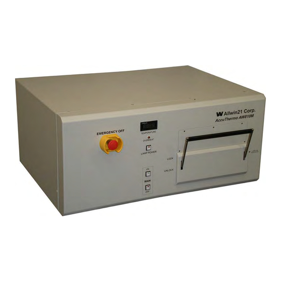
Allwin21 AccuThermo AW810M Technical Manual (437 pages)
Rapid Thermal Process System
Brand:
Allwin21
| Category:
Industrial Equipment
| Size: 5 MB
Table of Contents
Service Information
3
Warranty
4
Preface
6
Table of Contents
7
List of Figures
14
Introduction
17
System Description
17
Figure 1-1: Accuthermo AW810M System
17
Features
18
System Process Specifications
20
Safety Precautions
23
Overview
23
Notes, Cautions and Warnings
24
Safety Features
25
Utilities Inspection
26
System Operation
27
Maintenance
27
Gas Handling
28
Hazards
29
Electrical Shock Hazards
29
Process Gas Hazards
29
Process Byproduct Hazards
30
Oxygen Hazards
30
Thermal Hazards
31
Installation
33
Purchaser's Responsibility
33
Allwin21 Service
33
Field Service Installation
33
Training
33
Installation Process Overview
34
Installation Procedures
34
Required Tools
35
Installation Site Requirements
36
Facility Preparation
36
Space Requirements
36
Figure 3-1: AW810 Footprint and Elevation
36
Utility Connections
37
Figure 3-2: Accuthermo AW810M System Rear Utility Panel Connections
37
Adequate Cooling
38
Proper Tubing Size
39
Figure 3-3: Gas Pressure and Flow Rate Relationship for Different Tube Diameters
39
Air Conditioning
40
Electrical
41
Figure 3-1: Recommended Accuthermo® RTP System Power Distribution Diagram
42
Figure 3-2: 3-Phase AC Power Connections with Circuit Breaker
44
Figure 3-4: Japanese (200 VAC) Electrical Connections
46
Cooling Air
47
Figure 3-5: Recommended Non-Process Nitrogen Supply/Cda Configuration
48
Chamber Cooling Water
49
Figure 3-6: Optimal Cooling Water Supply Configuration
51
Process Gas
53
Figure 3-7: Optimal Process Gas Supply Configuration
54
Process Exhaust
55
Figure 3-8: Recommended Process Exhaust Configuration
55
Pneumatic Air
56
Figure 3-9: Recommended Pneumatic Configuration
56
Cabinet Exhaust
57
Figure 3-10: Recommended Cabinet Exhaust Configuration
57
Pyrometer Cooling Water
58
Unpacking and Inspecting the System
61
Uncrating
61
System Inspection
62
Unpacking
62
Installing the Computer
63
Overview of the Computer
63
Interconnection of the Computer Assembly
64
Connecting Computer to Accuthermo® RTP System
65
Figure 3-11: Computer to Accuthermo® RTP System Interconnect Diagram
65
Installing the Quartz Wafer Tray
66
Utility Check List
67
Power-Up & Power-Down
73
Overview
73
Utilities Inspection
74
Figure 4-1: Rear Utility Panel Connections
74
Front Control Panel
76
Figure 4-2: Front Control Panel
76
Full Power-Up and Testing
78
Initial Power-Up
78
Gas Setup Procedure
81
Manual Mode Tests
82
Daily Power-Up
84
System Operation
86
Full Power-Down
87
Daily Power-Down
88
Basic Operation
91
Overview
91
Menu Organization
93
Figure 5-1: Menu Organizational Map
93
Using the Menu Screens
95
Figure 5-2: Main Menu
95
Process for Production Screen
98
Figure 5-3: Process for Production Screen
98
Process for Engineer Screen
100
Figure 5-4: Process for Engineer Screen
100
Start a Process
102
Process Finished
105
Stop Process
105
Review the Process Data
106
Advanced Operation
109
Selecting a Recipe
109
Figure 6-1: Recipe Edit Selection Screen
109
Create and Modify a Recipe
110
Recipe Editor
112
Figure 6-2: Recipe Editor
112
Recipe Header
113
Data Entry Area
116
Keyboard Short-Cuts
119
Recipe Header Screen
120
Figure 6-3: Recipe Header Screen
120
Optimizing the Temperature Profile
122
Recipe Parameters
122
Recipe Lamp Zone Control
127
Figure 6-4: Recipe Zone Control Screen
127
Figure 6-5: Lamp Zone Factors in the Recipe Header Screen
127
Temperature Profile Stages
129
Figure 6-6: Temperature and Time Profile in a Recipe Cycle
129
Temperature Profile Optimization
131
Temperature Curves
136
Figure 6-7: Temperature Curves
136
Troubleshooting the Temperature Control
139
Figure 6-8: Oscillations
140
Figure 6-9: Overshoot
141
Figure 6-10: Undershoot
142
Process Control Alarms
143
Troubleshooting the Process Control
145
Administration
147
File Administration
147
File Extensions
147
Suggested ID Names
148
Software Setup
149
Maintenance Menu
149
Figure 7-1: Maintenance Menu
149
System Setup
150
Figure 7-2: System Setup Screen
150
Gas Setup
154
Figure 7-3: Gas Setup
154
Factory Setup
156
Figure 7-4: Factory Setup Screen
156
Control Board Selection
159
Figure 7-5: Board Configure Screen
159
GEM/SECS II Management
160
Figure 7-6: GEM/SECS II Management Menu
160
Figure 7-7: GEM/SECS II Manager Screen
161
Figure 7-8: GEM/SECS II Gemstone Setup Screen
161
Security
162
Figure 7-9: Password Setup
162
Figure 7-10: Level Setup
163
Theory of Operation
167
Lamps
167
Lamp Intensity
167
Figure 8-1: Sinusoidal Wave
168
Figure 8-2: Temperature Control Interconnect
169
Interlocks
170
Adequate Tube Size
172
Tube Is too Small
172
Tube Is too Long
172
Figure 8-3: Gas Pressure and Flow Rate Relationship for Different Tube Diameters
172
Cooling
173
Chamber Cooling
173
Quartz Isolation Tube Cooling
173
Wafer Cooling
174
Rate of Cooling
174
Cooling Control
175
Thermocouple
176
Pyrometer
177
Optical Pyrometry
177
The Extended Range Pyrometer (ERP)
177
Figure 8-4: ERP Dual Pyrometers Radiation Wavelengths
178
Figure 8-5: Extended Range Pyrometer
179
Figure 8-6: ERP and Thermocouple Temperature Measurements
180
Temperature
181
What Is Temperature
181
Measuring Temperature
182
Uniformity
183
LED Temperature Display
184
Gas Handling Subsystem
185
Gaas, Inp and Other Compound Semiconductor Processes
187
Introduction
187
Problems
187
Using the AW Control Software
188
Figure 8-7: Recipe with Preheat Step
188
Summary
189
Figure 8-8: Multi-Step Recipe to Check Stability
189
Maintenance & Diagnostics
191
Overview
191
Preventative Maintenance (PM) Schedule
193
Daily Maintenance
193
Weekly Maintenance
194
Monthly Maintenance
195
Quarterly Maintenance
196
Draining the Cooling Water
197
Removing the Cabinet Cover
198
Figure 9-1: Chamber Unit Cabinet Screw Locations
198
Quartzware (Tube and Tray)
200
Preventative Maintenance
200
Quartz Isolation Tube Removal and Installation
200
Figure 9-2: Gas Inlet Fitting Location (Rear of Chamber)
202
Figure 9-3: Front Flange Screw Locations
203
Figure 9-4: Removing the Isolation Tube
204
Figure 9-5: Flange O-Rings
205
Figure 9-6: Isolation Tube for Extended Range Pyrometer (ERP)
206
Quartz Wafer Support Tray Removal and Installation
209
Figure 9-7: Wafer Support Tray Removal and Installation
209
Quartz Wafer Support Tray Leveling
211
Figure 9-8: Leveling the Wafer Tray
211
Figure 9-9: Leveling Screw Locations (Top View)
212
Quartzware Cleaning
214
Quartzware Storage
217
Susceptor
218
Introduction
218
Figure 9-10: Susceptor Cover and Base
218
Using the Susceptor
219
Care and Cleaning
221
Calibration Menu
222
Figure 9-11: Calibration Menu
223
LED Display Calibration
224
Figure 9-12: LED Display Calibration
224
R40 Calibration
226
Figure 9-13: AW-900-058 Main Control Board
226
Thermocouple
227
Overview
227
Figure 9-14: Cantilever Thermocouple Assembly
228
Figure 9-15: Thermocouple Wafer Assembly
229
Installing the Thermocouple
230
Figure 9-16: Thermocouple Placement (Showing Cantilever Thermocouple)
230
Testing the Thermocouple
232
Installing and Testing the TC Wafer
232
Thermocouple Calibration
233
Figure 9-17: Thermocouple Calibration Screen
234
Thermocouple Diagnostics
236
Pyrometer
238
Overview
238
Pyrometer Calibration
239
Figure 9-18: Pyrometer Calibration List
241
Figure 9-19: Pyrometer Calibration Setup
242
Figure 9-20: Pyrometer Calibration Graph
246
Figure 9-21: Manual Control Screen
247
Figure 9-22: 900TC.RCP
249
Figure 9-23: Run of 900TC.RCP
250
Figure 9-24: 7911TC.RCP
250
Figure 9-25: Run of 7911TC.RCP
251
Figure 9-26: 7911PY.RCP
252
Figure 9-27: Run of 7911PY.RCP
253
Figure 9-28: Tube Pyrometer (White Line) Is Bad
255
Pyrometer Diagnostics
256
Checking the Pyrometer Calibration
258
Lamps
259
Lamp Zone Control
259
Figure 9-29: Lamp Zone Control Screen
260
Lamp Diagnostics
263
Verifying if the Lamps Are in Good Condition
265
Identifying a Bad Lamp
265
Replacing a Lamp
266
Gas Control
267
MFC Gas Flow Diagnostics
267
Gas Calibration
269
Figure 9-30: Gas Calibration Screen
269
Gas Leak Check Procedure
271
Figure 9-31: Recipe for Gas Leak Check
271
Chamber Calibration
272
Figure 9-32: Chamber Calibration Menu
273
Figure 9-33: Chamber Calibration Setup
274
Figure 9-34: Chamber Calibration Curve Graph
276
Figure 9-35: Chamber Calibration Curve Graph 2
277
Diagnostics & Testing
278
Diagnostics Screen
279
Figure 9-36: System Diagnostics Screen
280
Manual Control Screen
284
Figure 9-37: Manual Control Screen
284
Board Test Screen
285
Figure 9-38: Board Test Screen
285
Troubleshooting
287
Overview
287
Tips for Troubleshooting
288
Rules for Equipment Maintenance
288
Experiences for Equipment Troubleshooting
288
Testing Fuses
290
Figure 10-1: Location of Fuses
290
PCB Connectors
292
Figure 10-2: 2100-900-058 Main Control Board
292
Figure 10-3: 2100-900-038 Chamber Control Board
292
Led's on PCB
293
Figure 10-4: AW-900-058 LED Indicators
293
Figure 10-5: AW-900-038 LED Indicators
294
Alarm Codes
295
Faq
306
VAC Circuit
316
VAC Circuits
317
AC Phase Detection
318
Computer Problems
319
Computer Communication and Chamber Control Test Procedure
319
Computer will Not Power up
319
No Communication between the RTP Unit and the Computer
319
Contactor
320
Contamination
321
Cooling CDA (Nitrogen)
322
Cooling Water
323
Cooling Water Flow Troubleshooting
324
There Is no Water Flow
325
Software Indicates no Water Flow
326
Water Flow Rate Is too Low
326
Water Differential Pressure Is too Great
327
Water Temperature Is too Hot
327
Water Temperature Is too Cold
327
DC Power Supply
328
Fan & Solenoids
329
Gas Control
330
Gas DID Not Shut off after Process Ended
330
Gas Flow Rate and Pressure Decreases
330
Gas Feedback Does Not Match Gas Setpoint
330
Gas Leak Check Failure
330
Intensity
332
Intensity Varies and Spikes Greatly When Startinga Ramp
332
Intensity Went Up, but Temperature Went down
332
Lamp Problems
333
Lamps Do Not Go on
333
Lamp Contactor
334
Lamp Control Interlocks Check
336
Lamps Flicker
337
Lamps Go on and off
337
Lamps Go on When the Lamp Power Switch Is Turned on
338
Intensity Is Higher than Normal
339
LED Display
340
LED Display Goes "Crazy
340
Temperature on the LED Display and Computer Monitor Differ
340
Main Circuit Breaker Trips
341
Main Power
342
Overheat
343
Figure 10-6: Bottom View of Process Chamber
344
Process
345
Process Results Indicate Different Temperature, Thermocouple
346
Process Results Indicate Different Temperature, Pyrometer
346
Process Temperature Is Different than before to Get same Result
346
Pyrometer Chiller
347
Chiller will Not Start
347
Loss of Cooling Capacity
347
No External Circulation
347
Quartz Isolation Tube Broke
348
Samples Slide off Base Wafer
349
Temperature
350
Temperature Is Not Responding Correctly
350
Temperature Reading Is too Low or Jittery
353
Thermocouple
354
Thermocouple (TC) Keeps Breaking
354
Uniformity
355
Definition
355
Problem
355
Causes
355
Wafer Cooling
357
Water
358
No AW-RTP-900-008 Card or Card Connection Not Good
358
Schematics
361
Parts Guide
379
Overview
379
Outer Panels
380
Chassis - Front View
381
Chassis - Rear View
382
Chassis - Left View
384
Chassis - Back Wall
386
Chamber - Assembly
388
Quartzware
393
Thermocouples
393
Susceptors
393
Chamber - Rear View
394
Chamber - Triac Plate (3-Phase)
396
Gas Module
398
Chiller Assembly
400
Computer
401
Misc
401
Spare Parts Kit, Level 1
402
Spare Parts Kit, Level 2
403
Spare Parts Kit, Level 3
404
Appendix
407
A: DOS Commands at a Glance
407
B: Determining the Proper USB Drive Letter
411
C: Copying Process Data
412
D: Keyboard Shortcuts
414
E: Updating the Control Software
415
F: Backing up and Restoring the Software
417
G: Software Startup
422
H: Selection of the Purity of Gases
423
How to Order / Return Equipment
424
Maintenance Plans
429
K: Problem Reporting
430
Software Critique
432
M: Manual Revision History
434
Index
436
Advertisement
Advertisement
Related Products
Allwin21 GaSonics AURA 1000
Allwin21 Tegal 90Xe
Allwin21 Categories
Industrial Equipment
More Allwin21 Manuals
Login
Sign In
OR
Sign in with Facebook
Sign in with Google
Upload manual
Upload from disk
Upload from URL