Table of Contents
Advertisement
Quick Links
User Guide - TEMP - Sigfox RC1
Published
Category
Document version
Language
Type
Product/Service
https://s3-us-west-2.amazonaws.com/secure.notion-static.com/00e5f77c-913
9-455d-9f4a-e3aa1c618807/User_Guide_TEMP_IP68_Sigfox_RC1_V3.1.1_
(1).pdf
User Guide - TEMP - Sigfox RC1
SIGFOX SENSOR
V3.1.1
EN
User Guide
TEMP / TEMP2S EU868 / RC1
www.ime.de
1
Advertisement
Table of Contents

Related Manuals for IME adeunis TEMP Sigfox RC1


Summary of Contents for IME adeunis TEMP Sigfox RC1
- Page 1 User Guide - TEMP - Sigfox RC1 Published Category SIGFOX SENSOR Document version V3.1.1 Language Type User Guide Product/Service TEMP / TEMP2S EU868 / RC1 https://s3-us-west-2.amazonaws.com/secure.notion-static.com/00e5f77c-913 9-455d-9f4a-e3aa1c618807/User_Guide_TEMP_IP68_Sigfox_RC1_V3.1.1_ (1).pdf User Guide - TEMP - Sigfox RC1...
- Page 2 PRODUCTS AND REGULATORY INFORMATION This document applies to the following products : TEMP V4 IP68 Sigfox 863-870 ambient probe and remote probe TEMP V4 IP68 Sigfox 863-870 TEMP two external probes Part number: ARF8180BCA ARF8180BCB Firmware version: RTU version: V02.00.01 APP version: V02.01.00...
-
Page 3: Table Of Contents
TABLE OF CONTENTS PRODUCTS AND REGULATORY INFORMATION 1. PRODUCT PRESENTATION 1.1. General description 1.2. Dimensions 1.3. Electronic board 1.4. Two versions of the product 1.5. Technical specifications 1.5.1 General characteristics 1.5.2 Electric characteristics 1.5.3 Probes characteristics 1.5.4 Autonomy 1.5.5 Environmental conditions and ingress protection 2. -
Page 4: Product Presentation
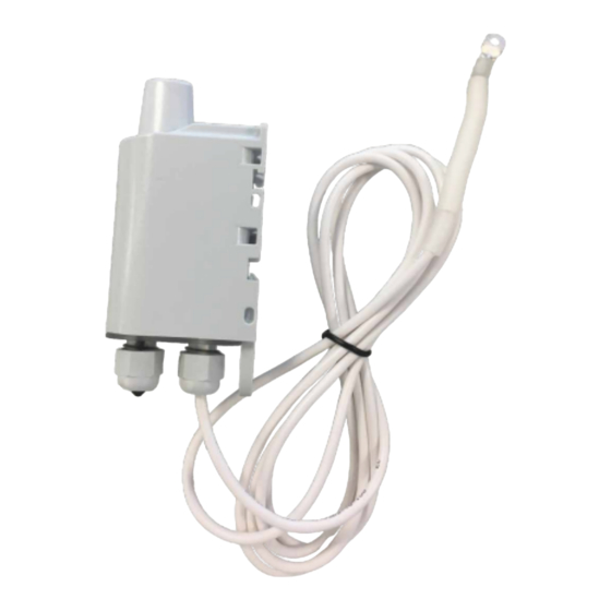
1. PRODUCT PRESENTATION IMPORTANT NOTE: The TEMP V4 IP68 Sigfox RC1 can be started with a magnet or switching the product in PRODUCTION mode with the IoT Configurator. Description : • The TEMP IP68 Sigfox RC1 is a ready-to-use radio device enabling temperatures to be measured and transmitted by wireless communication network. -
Page 5: General Description
1.1. General description User Guide - TEMP - Sigfox RC1... -
Page 6: Dimensions
1.2. Dimensions Values in millimeters User Guide - TEMP - Sigfox RC1... -
Page 7: Electronic Board
1.3. Electronic board 1.4. Two versions of the product Product with ambient probe and remote probe: User Guide - TEMP - Sigfox RC1... -
Page 8: Technical Specifications
Product with two external probes: 1.5. Technical specifications 1.5.1 General characteristics Parameters Value Working temperature -25°C / +70°C Dimensions 132 x 62 x 34mm Weight 148g 1 Remote probe, 185g 2 remote probes Casing IP 68 Radio standards EN300220-1 et EN300220-2... -
Page 9: Electric Characteristics
Parameters Value Sigfox network EU863-870 Max power transmission 14 dBm 1.5.2 Electric characteristics Supply Characteristics Value Unit Battery FANSO ER18505H+W36mm+51021 Voltage connector : Battery FANSO ER18505H+W36mm+51021 Current max connector : External : Input range 4.5 to 6.5 External :... -
Page 10: Autonomy
Characteristics Precision [+60°C/105°C] +/- 2°C CAUTION: Allow a few minutes for the probe to come back to room temperature before any manual operations to avoid mechanical damages. In addition, please respect the minimum and maximum temperatures for the sensor and the wire (cf. -
Page 11: Environmental Conditions And Ingress Protection
1.5.5 Environmental conditions and ingress protection The casing of the TEMP V4 IP68 Sigfox RC1 has been tested to ensure a certain level of dust and water protection. For dust: level 6 guarantees complete sealing against For water: level 8 guarantees at least a complete waterproof casing for more than 1 hour in one meter deep. -
Page 12: Park Mode
2.1.1 PARK mode The product is delivered in PARK mode, it is in standby mode and its consumption is minimal. To switch the product out of the Park* Mode pass a magnet across it for a duration higher than 5 seconds. The green LED illuminates to indicate the detection of the magnet and then flashes quickly during the product starting phase. -
Page 13: Transmission Modes
The “battery low” flag is automatically disappearing when the battery is replaced or when temperature conditions are favorable to the proper functioning of the battery. 2.2. Transmission modes The product allows to measure temperature on 2 probes or 1 probes only, to save the information and to send it according to 3 modes of emission. - Page 14 Periodical Over threshold Periodical and over transmission transmission threshold transmission • Sampling • Sampling period • Sampling period period (S321) = (S321) = 300 (300s x2 (S321) = 300 (300s x2 =10 900 (900s x2 =10 minutes) • min) • Number of...
- Page 15 User Guide - TEMP - Sigfox RC1...
- Page 16 Example of possible configurations: Theoretical Theoretical Associated con- Associated con- number of number of Case (no 100% alarm) with 2 probes activated Case (no 100% alarm) with 2 probes activated figuration figuration periodical frame periodical frame sent per day sent per day • ...
-
Page 17: Periodical Transmission With Or Without Historisation
2.2.1 Periodical transmission with or without historisation The product enables to measure and send the data from the probe following the diagram bellow. This periodical transmission can be done with or without historisation of the data. The product enables to activate or deactivate a probe. The 0x57 frame will be different depending if 1 or 2 probes are activated. - Page 18 User Guide - TEMP - Sigfox RC1...
- Page 19 Example without historisation : Register Encoding Value Result 1 sample every hour (1800 x 2 S321 Decimal 1800 seconds = 60 minutes) S320 Decimal 1 historisation for each sample S301 Decimal 1 transmission for each historisation S324 Decimal The 2 probes are activated...
-
Page 20: Periodical Transmission With Redundancy
2.2.2 Periodical transmission with redundancy The product enables to add redundancy in the frame sent (cf diagram bellow). Thanks to the redundancy the product will save samples locally in order to resend them in the next frame. Parameters associated to this mode:... - Page 21 User Guide - TEMP - Sigfox RC1...
-
Page 22: Transmission On Threshold Overpassed
2.2.3 Transmission on threshold overpassed www.ime.de The product enables the detection of a threshold overpassed (high and low) for each probe, as described in the diagram bellow: The sampling period (reading) enables to determine when the product will do the temperature measure and so the frequency at which the product will detect an overpassed threshold. - Page 23 Explication of the thresholds and their hysteresis: The settings associated with this mode of operation are: • Sampling period (register 321). • The activation of the probes (register 324). • Alarm configuration of the probe 1 (register 330) and probe 2 (register 340).
-
Page 24: Transmission On Threshold Overpassed With Alarm Repetition
Register Encoding Value Result Hysteresis of the high threshold is S332 Decimal 5°C, so the come back to normal is at 65°C S333 Decimal Low threshold is 10°C Hysteresis of the low threshold is S334 Decimal 2°C, so the come back to normal is at 12°C... - Page 25 User Guide - TEMP - Sigfox RC1...
- Page 26 Settings associated to this operating mode are: Sampling period (register 321), Alarm repetition (register 322), Activation of the probes (register 324). Alarm configuration on probe 1 (register 330) and probe 2 (register 340). High threshold on the probe 1 (register 331) and probe 2 (register 341).
-
Page 27: Transmission Of The Keep Alive Frame
A sampling (reading) every 10 minutes (300 x 2 seconds = 10 minutes) As long as the alarm is active (threshold always overpassed), this alarm will be repeated every 2 samples (so every 20 minutes). *The “alarm status” byte gives the information if the alert is activated or not and so allows to dissociate a 0x58 frame sent to alert that the threshold is overpassed from a 0x58 frame sent to inform about come back to normal. -
Page 28: Operation Of The Led
Transmission period of the keep alive frame, from 20 seconds to 7 days (register 300). Example: Register Encoding Value Result The keep alive frame is sent every: S300 Decimal 8640 8640x10 seconds =1440min so 24h (so once per day) 2.3. -
Page 29: Registers And Frame Description
3. REGISTERS AND FRAME DESCRIPTION To know the content of the registers and of each frames (uplink and downlink) of the product, refers to the TECHNICAL REFERENCE MANUAL of the TEMP. 4. CONFIGURATION AND INSTALLATION 4.1. Configuration and installation of the transmitter To configure the product, it is recommended to use the IoT Configurator (android and Windows application). -
Page 30: Wiring
5. WIRING www.ime.de 5.1. Disconnect a probe To disconnect a probe, please follow these instructions: CAUTION: To maintain the IP 68 it is important to screw the cable glands fully and screw the screws with a PZ.1 head and a tightening torque of 0.9 N.m. -
Page 31: Wiring A Probe
5.2. Wiring a probe In order to wire a probe, please follow these instructions: CAUTION: To maintain the IP 68 it is important to screw the cable glands fully and screw the screws with a PZ.1 head and a tightening torque of 0.9 N.m. -
Page 32: Wiring External Supply
5.3. Wiring external supply A terminal is present in the product to connect an external supply in order to: Improve the autonomy of the product Send more frames more Connect the power cable to the “+” terminal block (V +) with a power supply between 4.5 V and 6.5 V and connect the earth to the “-”... - Page 33 Version Contents V3.1.1 More information about the battery User Guide - TEMP - Sigfox RC1...
Need help?
Do you have a question about the adeunis TEMP Sigfox RC1 and is the answer not in the manual?
Questions and answers