Aspar RS485 MODBUS Module 6TE User Manual
Expansion module-6 temperature inputs
Hide thumbs
Also See for RS485 MODBUS Module 6TE:
- User manual (16 pages) ,
- User manual (17 pages) ,
- User manual (17 pages)

Related Manuals for Aspar RS485 MODBUS Module 6TE


Summary of Contents for Aspar RS485 MODBUS Module 6TE
- Page 1 RS485 MODBUS Module 6TE Expansion Module – 6 temperature inputs Version 1.5 User Manual Manufactured for...
- Page 2 RS485 MODBUS Module 6TE User Manual Thank you for choosing our product. This manual will help you with proper support and proper operation of the device. The information contained in this manual have been prepared with utmost care by our professionals and serve as a description of the product without incurring any liability for the purposes of commercial law.
-
Page 3: Safety Rules
RS485 MODBUS Module 6TE User Manual 1. Safety rules • Before first use, refer to this manual • Before first use, make sure that all cables are connected properly • Please ensure proper working conditions, according to the device specifications (eg: supply voltage, temperature, maximum power consumption) •... -
Page 4: Technical Specifications
RS485 MODBUS Module 6TE User Manual 2.2. Technical Specifications Voltage 10-38VDC; 10-28VAC Power Supply Maximum Current 120 mA @ 12V / 100 mA @ 24V No of inputs Pt100 operation range -200°C - +850°C Pt500 operation range -200°C - +850°C Pt1000 operation range -200°C - +850°C... -
Page 5: Dimensions Of The Product
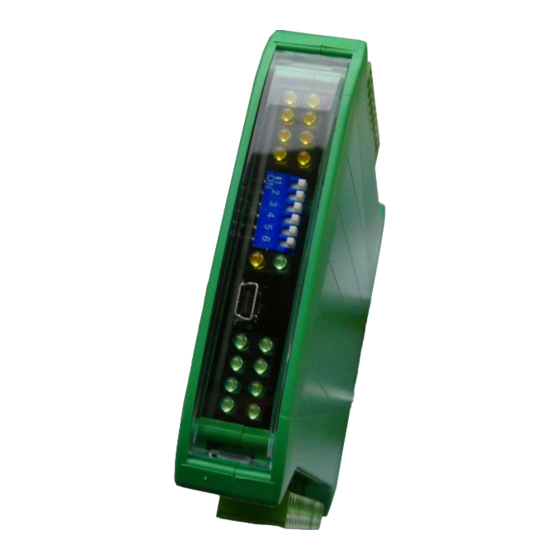
RS485 MODBUS Module 6TE User Manual 2.3. Dimensions of the product Look and dimensions of the module are shown below. The module is mounted directly to the rail in the DIN industry standard. Power connectors, communication and IOs are at the bottom and top of the module. USB connector configuration and indicators located on the front of the module. -
Page 6: Communication Configuration
RS485 MODBUS Module 6TE User Manual 3. Communication configuration 3.1. Grounding and shielding In most cases, IO modules will be installed in an enclosure along with other devices which generate electromagnetic radiation. Examples of these devices are relays and contactors, transformers, motor controllers etc. This electromagnetic radiation can induce electrical noise into both power and signal lines, as well as direct radiation into the module causing negative effects on the system. -
Page 7: Types Of Modbus Registers
RS485 MODBUS Module 6TE User Manual 3.4. Types of Modbus Registers There are 4 types of variables available in the module Beginning Modbus Type Variable Access address Command 00001 Digital Outputs 1, 5, 15 Read & Write 10001 Digital Inputs... -
Page 8: Configuration Registers
RS485 MODBUS Module 6TE User Manual 3.5.3. Configuration registers Modbus Name Values Address 0 – 2400 1 – 4800 2 – 9600 3 – 19200 40003 0x02 Baud rate 4 – 38400 5 – 57600 6 – 115200 other – value * 10 0 –... -
Page 9: Indicators
RS485 MODBUS Module 6TE User Manual 4. Indicators 6 sensors state 2 digital outputs state Power Supply Communication Indicator Description Power supply LED indicates that the module is correctly powered. Communication The LED lights up when the unit received the correct packet and sends the answer. -
Page 10: Module Connection
RS485 MODBUS Module 6TE User Manual 5. Module Connection Expansion Module – 6 temperature inputs User Manual Version 1.5 10 / 16... -
Page 11: Switches
RS485 MODBUS Module 6TE User Manual 6. Switches Switch Function Description Module address +1 Module address +2 Module address +4 Setting module address from 0 to 31 Module address +8 Module address +16 Restoring default settings Restoring default settings (see 3.5.1 - Default settings and 3.5.2 - Restore the default configuration). -
Page 12: Modules Registers
RS485 MODBUS Module 6TE User Manual 7. Modules Registers 7.1. Registered access Modbus Dec Hex Register Name Access Description 30001 0x00 Version/Type Read Version and Type of the device 30002 0x01 Switches Read Switches state 40003 0x02 Baud rate Read & Write... - Page 13 RS485 MODBUS Module 6TE User Manual 40071 0x46 MIN alarm level 3 Read & Write 40072 0x47 MIN alarm level 4 Read & Write 40073 0x48 MIN alarm level 5 Read & Write 40074 0x49 MIN alarm level 6 Read & Write...
-
Page 14: Bit Access
RS485 MODBUS Module 6TE User Manual +16 – temperature from input 5 +32 – temperature from input 6 +256 – Output is set if value is greater than Alarm Value (register 40091 or 40092) („cooling”) +512 – Output is set if value is less than Alarm Value... -
Page 15: Configuration Software
RS485 MODBUS Module 6TE User Manual 8. Configuration software Modbus Configurator is software that is designed to set the module registers responsible for communication over Modbus network as well as to read and write the current value of other registers of the module. This program can be a convenient way to test the system as well as to observe real-time changes in the registers. -
Page 16: Table Of Contents
RS485 MODBUS Module 6TE User Manual Table of content 1. Safety rules............................3 2. Module Features..........................3 2.1. Purpose and description of the module..................3 2.2. Technical Specifications......................4 2.3. Dimensions of the product......................5 3. Communication configuration......................6 3.1. Grounding and shielding......................6 3.2. Network Termination........................6 3.3.
Need help?
Do you have a question about the RS485 MODBUS Module 6TE and is the answer not in the manual?
Questions and answers