
Related Manuals for Aspar Mini Series


Summary of Contents for Aspar Mini Series
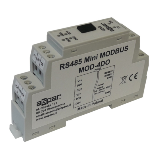
- Page 1 Mini Modbus 4DO Expansion Module – 4 digital outputs Version 1.3 User Manual Manufactured for...
- Page 2 Mini Modbus 4DO User Manual Thank you for choosing our product. This manual will help you with proper support and proper operation of the device. The information contained in this manual have been prepared with utmost care by our professionals and serve as a description of the product without incurring any liability for the purposes of commercial law.
-
Page 3: Safety Rules
Mini Modbus 4DO User Manual 1. Safety rules • Before first use, refer to this manual • Before first use, make sure that all cables are connected properly • Please ensure proper working conditions, according to the device specifications (eg: supply voltage, temperature, maximum power consumption) •... -
Page 4: Technical Specifications
Mini Modbus 4DO User Manual 2.2. Technical Specifications Voltage 10-38VDC; 20-28VAC Power Supply Maximum Current 69 mA @ 12V / 38 mA @ 24V No of outputs Max Voltage Digital Outputs Max current 250mA Output Type Work -10 °C - +50°C Temperature Storage -40 °C - +85°C... -
Page 5: Dimensions Of The Product
Mini Modbus 4DO User Manual 2.3. Dimensions of the product Look and dimensions of the module are shown below. The module is mounted directly to the rail in the DIN industry standard. 3. Communication configuration 3.1. Grounding and shielding In most cases, IO modules will be installed in an enclosure along with other devices which generate electromagnetic radiation. -
Page 6: Types Of Modbus Registers
Mini Modbus 4DO User Manual 3.3. Types of Modbus Registers There are 4 types of variables available in the module Beginning Modbus Type Variable Access address Command 00001 Digital Outputs 1, 5, 15 Read & Write 10001 Digital Inputs Read Registered 30001 Input Registers... -
Page 7: Configuration Registers
Mini Modbus 4DO User Manual 3.4.2. Configuration registers Modbus Name Values Address 0 – 2400 1 – 4800 2 – 9600 3 – 19200 40003 0x02 Baud rate 4 – 38400 5 – 57600 6 – 115200 other – value * 10 0 –... -
Page 8: Block Diagram
Mini Modbus 4DO User Manual 5. Block diagram OUT1 OUT2 μC OUT3 485+ RS485 485- OUT4 6. Module Connection Expansion Module– 4 digital outputs User Manual Version 1.3 8 / 11... -
Page 9: Modules Registers
Mini Modbus 4DO User Manual 7. Modules Registers 7.1. Registered access Modbus Dec Hex Register Name Access Description 30001 0x00 Version/Type Read Version and Type of the device 30002 0x01 Address Read Module address 40003 0x02 Baud rate Read & Write RS485 baud rate 40004 0x03 Stop Bits &... -
Page 10: Configuration Software
Mini Modbus 4DO User Manual 8. Configuration software Modbus Configurator is software that is designed to set the module registers responsible for communication over Modbus network as well as to read and write the current value of other registers of the module. This program can be a convenient way to test the system as well as to observe real-time changes in the registers. -
Page 11: Table Of Contents
5. Block diagram..........................8 6. Module Connection..........................8 7. Modules Registers..........................9 7.1. Registered access........................9 7.2. Bit access..........................9 8. Configuration software........................10 Manufactured for: Aspar s.c. ul. Oliwska 112 80-209 Chwaszczyno Poland ampero@ampero.eu www.ampero.eu Tel. +48 58 351 39 89; +48 58 732 71 73 Expansion Module–...
Need help?
Do you have a question about the Mini Series and is the answer not in the manual?
Questions and answers