
Related Manuals for Aspar SDM-8I8O


Summary of Contents for Aspar SDM-8I8O
- Page 1 SDM-8I8O Expansion Module – 8 digital inputs, 8 digital outputs Version 1.3 User Manual Manufactured for...
- Page 2 SDM-8I8O User Manual Thank you for choosing our product. This manual will help you with proper support and proper operation of the device. The information contained in this manual have been prepared with utmost care by our professionals and serve as a description of the product without incurring any liability for the purposes of commercial law.
-
Page 3: Safety Rules
2. Module Features 2.1. Purpose and description of the module The SDM-8I8O module is an innovative device that provides a simple and cost- effective extension of the number of lines of input and output in popular PLCs. The module has 8 digital inputs with configurable timer/counter option and 8 digital outputs. -
Page 4: Technical Specifications
SDM-8I8O User Manual 2.2. Technical Specifications Voltage 10-30 VDC; 10-28VAC DC: 100 mA @ 24VDC Power Supply Maximum Current AC: 125 mA @ 24VAC Maximum power consumption DC: 2.4W; AC: 3VA No of inputs Voltage range 0 – 36V Low State „0”... -
Page 5: Dimensions Of The Product
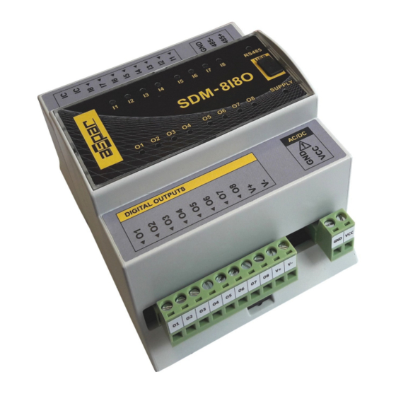
SDM-8I8O User Manual 2.3. Dimensions of the product Look and dimensions of the module are shown below. The module is mounted directly to the rail in the DIN industry standard. Power connectors, communication and IOs are at the bottom and top of the module. USB connector configuration and indicators located on the front of the module. -
Page 6: Communication Configuration
SDM-8I8O User Manual 3. Communication configuration 3.1. Grounding and shielding In most cases, IO modules will be installed in an enclosure along with other devices which generate electromagnetic radiation. Examples of these devices are relays and contactors, transformers, motor controllers etc. This electromagnetic radiation can induce electrical noise into both power and signal lines, as well as direct radiation into the module causing negative effects on the system. -
Page 7: Types Of Modbus Registers
SDM-8I8O User Manual 3.4. Types of Modbus Registers There are 4 types of variables available in the module. Modbus Type Beginning adress Variable Access Command 00001 Digital Outputs 1, 5, 15 Read & Write 10001 Digital Inputs Read Registered 30001... -
Page 8: Configuration Registers
SDM-8I8O User Manual 3.5.3. Configuration registers Modbus Name Values 0 – 2400 1 – 4800 2 – 9600 3 – 19200 40003 0x02 Baud rate 4 – 38400 5 – 57600 6 – 115200 other – value * 10 0 – none 1 –... -
Page 9: Switches
SDM-8I8O User Manual 4. Switches Switch Function Description Module address +1 Module address +2 Module address +4 Module address +8 Setting module address from 0 to 127 Module address +16 Module address +32 Module address +64 Restoring default settings Restoring (see 3.5.1 - Default settings i 3.5.2 - Restore the... -
Page 10: Front Panel Removing
SDM-8I8O User Manual 5. Front panel removing To remove the panel and gain access to the switch, you must pry open the panel using a thin tool (eg a small screwdriver) as in the picture below. Expansion Module – 8 digital inputs, 8 digital outputs User Manual Version 1.3... -
Page 11: Indicators
SDM-8I8O User Manual 6. Indicators Inputs 1 – 8 state Communication mini USB configuration connector Power supply Outputs 1 – 8 state Indicators Description Power supply LED indicates that the module is correctly powered. Communication The LED lights up when the unit received the correct packet and sends the answer. -
Page 12: Module Connection
SDM-8I8O User Manual 7. Module Connection Expansion Module – 8 digital inputs, 8 digital outputs User Manual Version 1.3 12 z 18... - Page 13 SDM-8I8O User Manual Expansion Module – 8 digital inputs, 8 digital outputs User Manual Version 1.3 13 z 18...
-
Page 14: Modules Registers
SDM-8I8O User Manual 8. Modules Registers 8.1. Registered access Modbus Register Name Access Description 30001 0x00 Version/Type Read Version and Type of the device 30002 0x01 Switches Read Switches state 40003 0x02 Baud rate Read & Write RS485 baud rate 40004 0x03 Stop Bits &... - Page 15 SDM-8I8O User Manual Modbus Register Name Access Description 40085 0x54 CCounter 1 LSB Read & Write 32-bit value of captured counter 1 40086 0x55 CCounter 1 MSB Read & Write 40087 0x56 CCounter 2 LSB Read & Write 32-bit value of captured counter 2...
-
Page 16: Bit Access
SDM-8I8O User Manual 8.2. Bit access Modbus Register name Access Description Address Address Address 0x0C0 Default state of output 1 Read & Write Default state of output 1 0x0C1 Default state of output 2 Read & Write Default state of output 2 0x0C2 Default state of output 3 Read &... - Page 17 SDM-8I8O User Manual Modbus Register name Access Description Address Address Address 2129 2120 0x848 Captured 1 Read & Write Captured value of counter 1 2130 2129 0x849 Captured 2 Read & Write Captured value of counter 2 2131 2130 0x84A Captured 3 Read &...
-
Page 18: Configuration Software
SDM-8I8O User Manual 9. Configuration software Modbus Configurator is software that is designed to set the module registers responsible for communication over Modbus network as well as to read and write the current value of other registers of the module. This program can be a convenient way to test the system as well as to observe real-time changes in the registers. -
Page 19: Table Of Contents
SDM-8I8O User Manual Table of content 1. Safety rules............................3 2. Module Features..........................3 2.1. Purpose and description of the module..................3 2.2. Technical Specifications......................4 2.3. Dimensions of the product......................5 3. Communication configuration......................6 3.1. Grounding and shielding......................6 3.2. Network Termination........................6 3.3. Setting Module Address in RS485 Modbus Network...............6 3.4.
Need help?
Do you have a question about the SDM-8I8O and is the answer not in the manual?
Questions and answers