Advertisement
Quick Links
HTV8BLEEMVP*1B HTV8BLEEMVP*2B HVT8BLEEMVP*3B HTVDBLMVP*1B HTVDBLMVP*2B HTVDBLMVP*3B
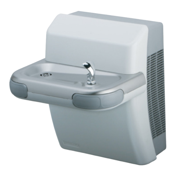
HTVBLEE-MVP Series Barrier-Free Water Coolers
56
62
41
35
40
4
22, 29
23, 61
17
35
28
31
Fig. 1
OWNERS MANUAL
24
34
43
21, 29
4
35
45, 46
63
18, 20, 26
53
69
64
27
44
12
54, 68
65
65
25
7
PAGE 1
8
58
32, 36, 51
35
52
33
67
30
(A) - See. Fig. 11
13, 15, 59, 60
42
4, 16
23, 61
55
57
30
67
66, 70
2, 3, 5
98413C (Rev. D - 11/08)
Advertisement

Related Manuals for Halsey Taylor HTVBLEE-MVP Series


Summary of Contents for Halsey Taylor HTVBLEE-MVP Series
- Page 1 HTV8BLEEMVP*1B HTV8BLEEMVP*2B HVT8BLEEMVP*3B HTVDBLMVP*1B HTVDBLMVP*2B HTVDBLMVP*3B OWNERS MANUAL HTVBLEE-MVP Series Barrier-Free Water Coolers 32, 36, 51 54, 68 (A) - See. Fig. 11 22, 29 23, 61 13, 15, 59, 60 4, 16 23, 61 21, 29 45, 46 18, 20, 26 66, 70 Fig.
- Page 2 HTV8BLEEMVP*1B HTV8BLEEMVP*2B HVT8BLEEMVP*3B HTVDBLMVP*1B HTVDBLMVP*2B HTVDBLMVP*3B Fig. 2 98413C (Rev. D - 11/08) PAGE 2...
- Page 3 HTV8BLEEMVP*1B HTV8BLEEMVP*2B HVT8BLEEMVP*3B HTVDBLMVP*1B HTVDBLMVP*2B HTVDBLMVP*3B HANGER BRACKET (Item 10) HANGER BRACKET & TRAP INSTALLATION 1) Remove the hanger bracket fastened to back of the cooler by removing one (1) screw. 2) Mount the hanger bracket as shown in Fig. 2 & Fig 3. NOTE: Hanger Bracket MUST be supported securely.
-
Page 4: Top Cover Removal
HTV8BLEEMVP*1B HTV8BLEEMVP*2B HVT8BLEEMVP*3B HTVDBLMVP*1B HTVDBLMVP*2B HTVDBLMVP*3B Top Cover Removal Please remove bottom cover before removing top cover. To remove top cover (Item 37), use a small screwdriver to release the snap for the top cover as shown in Fig. 5. Then pull the small tabs on each side of the top cover outward slightly and slide upward to remove. - Page 5 HTV8BLEEMVP*1B HTV8BLEEMVP*2B HVT8BLEEMVP*3B HTVDBLMVP*1B HTVDBLMVP*2B HTVDBLMVP*3B Removing the basin To remove the basin (Item 12 or 34), remove two screws (Item 58) on top of the basin (Shown in Fig. 7). Then remove the four screws (Item 71) located underneath the dispenser bottom (Item 39 or 50) as shown in Fig.
-
Page 6: Regulator Replacement
HTV8BLEEMVP*1B HTV8BLEEMVP*2B HVT8BLEEMVP*3B HTVDBLMVP*1B HTVDBLMVP*2B HTVDBLMVP*3B Regulator Replacement To replace the regulator (Item 51), separate the two tabs (Shown in Fig. 10) to remove the regulator holder from the dispenser bottom (Item 39 or 50). Then unscrew plastic retaining nut to remove regulator. FIG. - Page 7 HTV8BLEEMVP*1B HTV8BLEEMVP*2B HVT8BLEEMVP*3B HTVDBLMVP*1B HTVDBLMVP*2B HTVDBLMVP*3B SENSOR WITH FILTER LIFE INDICATOR: (B) The electronic sensor includes LED filter status indicators that are factory preset to monitor filter life. The sensor monitors the “ON” time of the water valve solenoid and keeps track of total time water is dispensed. There are (3) LED’s and indicates the following: Green LED (Good) indicates that the filter is operating within 0% - 80% of its life.
- Page 8 HTV8BLEEMVP*1B HTV8BLEEMVP*2B HVT8BLEEMVP*3B HTVDBLMVP*1B HTVDBLMVP*2B HTVDBLMVP*3B Switch Activation Detail FIG. 13 Closed switch Open switch 98413C (Rev. D - 11/08) PAGE 8...
- Page 9 HTV8BLEEMVP*1B HTV8BLEEMVP*2B HVT8BLEEMVP*3B HTVDBLMVP*1B HTVDBLMVP*2B HTVDBLMVP*3B FIG. 14 Pushbar Replacement Please remove the basin before removing the pushbars. Remove screw (Item 73) that holds pushbars in place. Then simply slide the pushbars upward and remove. Do not discard the small springs or screws. When replacing pushbars do not over tighten screws, because the pushbars need to move freely.
-
Page 10: Bottom Cover Removal
HTV8BLEEMVP*1B HTV8BLEEMVP*2B HVT8BLEEMVP*3B HTVDBLMVP*1B HTVDBLMVP*2B HTVDBLMVP*3B FIG. 16 See Fig. 11 32, 36, 51 Bottom Cover Removal To access the refrigeration system and plumbing connections, remove two screws (Item 66) to remove bottom cover (Item 38). 98413C (Rev. D - 11/08) PAGE 10... - Page 11 HTV8BLEEMVP*1B HTV8BLEEMVP*2B HVT8BLEEMVP*3B HTVDBLMVP*1B HTVDBLMVP*2B HTVDBLMVP*3B FIG. 17 FIG. 18 BLACK LED PCB WHITE GREEN YELLOW SOLENOID SENSOR PURPLE JUMPER VALVE GRND CONNECTS TO SENSOR OVERLOAD ON LESS REFRIG. UNIT SOLENOID VALVE GREEN PURPLE 14 (Black Jumper Wire) JUMPER COMPRESSOR COLD CONTROL CONNECTS TO SENSOR ON...
- Page 12 HTV8BLEEMVP*1B HTV8BLEEMVP*2B HVT8BLEEMVP*3B HTVDBLMVP*1B HTVDBLMVP*2B HTVDBLMVP*3B PARTS LIST 220V-50Hz PARTS LIST ITEM NO. PART NO. DESCRIPTION ITEM NO. PART NO. DESCRIPTION 100322740560 Gasket - Bubbler (upper and lower) 31431C Fan Motor 100806740570 Grommet - Compressor Mtg. 36050C Relay 101516143550 Stud - Compressor Mtg. 36066C Power Cord (Refrig.
Need help?
Do you have a question about the HTVBLEE-MVP Series and is the answer not in the manual?
Questions and answers