Table of Contents
Advertisement
Quick Links
Advertisement
Table of Contents

Subscribe to Our Youtube Channel
Related Manuals for Vega TS-11


Summary of Contents for Vega TS-11
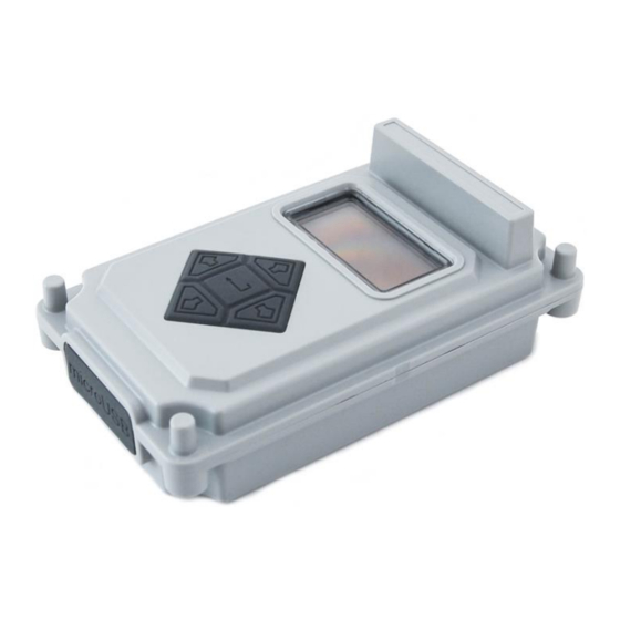
- Page 1 NETWORK TESTER VEGA TS-11 User Manual User Manual contains information how to work with LoRaWAN™ network autonomic tester Vega TS-11, and also contains warranty terms and conditions and rules for operating, storage and transportation www.vega-absolute.ru www.vega-absolute.ru...
- Page 3 Document information Title Network tester Vega TS-11 Document type Manual – translation from Russian Document number V02-TS11-01 Revision and date 02 – 27.12.2017 This document applies to the following products: Product name Type number End devices Vega TS-11 Revision history...
-
Page 4: Table Of Contents
Vega TS-11 / User Manual ОГЛАВЛЕНИЕ 1 DESCRIPTION AND OPERATION ............................3 2 SPECIFICATION .................................... 5 3 FAST NETWORK TESTING ................................ 6 4 DEVICE OPERATING ................................... 7 User interface ....................................7 Work screen 1 –Uplink and Downlink demodulation margin ................... 8 Work screen 2 –... -
Page 5: Description And Operation
Vega TS-11 / User Manual 1 DESCRIPTION AND OPERATION Network tester Vega TS-11 is designed for testing LoRaWAN networks while them is deploying and setting up Tester sends a special signal to the LoRaWAN™ network (‘Uplink’ packet), in response to which the tester received a confirmation (‘Downlink’... - Page 6 Vega TS-11 / User Manual RSSI (Received signal strength indicator) – «Downlink» signal power (dBm); Receiving window number at which confirmation was received (1 or 2); UDM - Uplink demodulation margin (hereinafter UM); DDM - Downlink demodulation margin (hereinafter DM);...
-
Page 7: Specification
Vega TS-11 / User Manual 2 SPECIFICATION Main Operating temperatures -40…+85 °С Display OLED, 1,3” USB-port micro-USB, 5 V, 500 mA LoRaWAN LoRaWAN class А Antenna type internal Sensitivity -138 dBm Radio coverage in restrained urban conditions Up to 5 km... -
Page 8: Fast Network Testing
Vega TS-11 / User Manual 3 FAST NETWORK TESTING Press ‘Up’ Press ‘OK’ button: button The first pressing – connection to the network, the second – network test Successful transmissions in percent Gateways No signal / no number data Uplink demodulation... -
Page 9: Device Operating
Vega TS-11 / User Manual 4 DEVICE OPERATING USER INTERFACE Tester equipped with control buttons, sound speaker and OLED display. Every pressing on the button accompaniment with sound signal if device sound is not off. To common main menu it need to press ‘OK’ button while device is on. Menu appears independent on what was on the display before button pressing. -
Page 10: Work Screen 1 -Uplink And Downlink Demodulation Margin
Vega TS-11 / User Manual WORK SCREEN 1 –UPLINK AND DOWNLINK DEMODULATION MARGIN First work screen appears just after device switch on. Herewith the data is not available on it. Work screen 1 allows you to get the follow information: Number of visible gateways;... - Page 11 Vega TS-11 / User Manual ‘Gateway’ icon - displays the activity of the communication process as an animation. Animation continues until the confirmation is accepted or the receiving window timeout expires. Number of gateways - the number of gateways received the last packet from the network tester successfully.
- Page 12 Vega TS-11 / User Manual A shaded bar appears on the DM diagram if a failed attempt is made also. In total, the network tester takes three attempts to join the network. Three failed attempts to join the network After successful joining the network, you can start testing the network. There are two ways: manual and automatic.
- Page 13 Vega TS-11 / User Manual Diagrams DM and UM - the arrow indicates the direction of the radio signal propagation, and the diagram shows the history of its change. The level of each bar on diagram shows the demodulation margin of a particular packet. The latest (recent) radio communication is displayed on the bar located next to the arrow.
-
Page 14: Work Screen 2 - Full Information About The Network
Vega TS-11 / User Manual WORK SCREEN 2 – FULL INFORMATION ABOUT THE NETWORK Switching between screens is carried out by pressing ‘Left’ and ‘Right’ buttons. During the testing process, you can freely navigate between them to get more complete information about the network. - Page 15 Vega TS-11 / User Manual Unlike other screens, the work screen 2 displays information only about the last communication session. The accumulated data here is the PER coefficient and the total number of received / transmitted packets. Percent of successful transmissions – PER (Packet error rate) coefficient is calculated as the ratio of the number of confirmations received by the tester from the network to the total number of requests, expressed as a percentage.
- Page 16 Vega TS-11 / User Manual Parameters of the latest packet transmitted by tester – to the left of the title bar there is information is displayed from top to bottom in order: COUNT – total number of ‘Uplink’ packets transmitted by the tester;...
-
Page 17: Work Screen 3 - Downlink Signal Rssi And Uplink Demodulation Margin Diagrams
Vega TS-11 / User Manual WORK SCREEN 3 – DOWNLINK SIGNAL RSSI AND UPLINK DEMODULATION MARGIN DIAGRAMS Work screen 3 allows you to get the follow information: RSSI (Received signal strength indicator) – ‘Downlink’ signal power expressed as dBm;... - Page 18 Vega TS-11 / User Manual packet is send, the diagram shifts to the right, and the bar corresponding to the last received value appears on the left. If the communication session was successful and the data was received, then the bar on the diagram is filled with white color, if the session has not passed or the data is not received, then the bar is shaded.
-
Page 19: Settings
Vega TS-11 / User Manual SETTINGS To go to the settings menu, you need to call up the main menu by clicking on the ‘OK’ button. Press the ‘Left’ / ‘Right’ button to move the cursor to select the ‘Settings’ icon and press the ‘OK’... - Page 20 Vega TS-11 / User Manual The custom frequency plan is limited in the range of 860-960 MHz. The data rate (DR) of the second receiving window (RX2) can take values from 0 to 5, where 0 corresponds to spread factor 12 (SF12).
-
Page 21: Automatic Test Mode
Vega TS-11 / User Manual AUTOMATIC TEST MODE In the automatic mode, the tester will send requests itself with the period specified in settings, and also by pressing the ‘Up’ button. Automatic requests period will not be shifted when the request initiates by the ‘Up’ button pressing. The period may be equal to any value from 30 seconds to 24 hours accurate to a second. -
Page 22: Shutdown
FIRMWARE UPDATE Updating the firmware of the network tester is carried out through the micro USB port using the configurator - "Vega LoRaWAN configurator". The configurator can be downloaded from http://iotvega.com/ in the Soft section. The firmware file can be downloaded from the product page - Network Tester. - Page 23 Vega TS-11 / User Manual 3. Press ‘Update firmware’ button. The dialog window will appears. Choose ‘Yes’ and specify the path to the firmware file with the extension *.vbf 4. Connect the network tester to a personal computer via a USB port and turn on the network tester.
- Page 24 5. While the loader is active (while ‘BOOT’ is displayed on the tester's screen) it is necessary to click the ‘Connect’ button in the "Vega LoRaWAN configurator" application. The firmware file will be downloaded. The boot process is displayed both in the configurator and on the network tester screen.
-
Page 25: Storage And Transportation Requirements
Vega TS-11 / User Manual 5 STORAGE AND TRANSPORTATION REQUIREMENTS The network tester Vega TS-11 shall be stored in the original packaging in heated room at temperatures +5°С to +40°С and relative humidity less than 85%. The tester shall be transported in covered freight compartments of all types at any distance at temperatures -40°C to +85°C. -
Page 26: Content Of The Package
Vega TS-11 / User Manual 6 CONTENT OF THE PACKAGE Network tester is delivered complete with: Network tester Vega TS-11 – 1 pc. Screw – 4 pcs. Factory certificate – 1 pc. Revision 02 - 27.12.2017... -
Page 27: Warranty
Vega TS-11 / User Manual 7 WARRANTY The warranty period for the device is 5 years from the date of sale. The manufacturer is obligated to provide repair services or replace the failed device during the entire warranty period. The consumer undertakes to comply with the terms and conditions of transportation, storage and operation specified in this user manual. - Page 29 User Manual © «Vega-Absolute» OOO 2017...
Need help?
Do you have a question about the TS-11 and is the answer not in the manual?
Questions and answers