Malossi FORCE MASTER 2.1 Assembly Instructions Manual
Hide thumbs
Also See for FORCE MASTER 2.1:
- Assembly instructions manual (56 pages) ,
- Manual (54 pages) ,
- Assembly instructions manual (49 pages)
Table of Contents
Advertisement
Available languages
Available languages
Quick Links
Advertisement
Table of Contents

Related Manuals for Malossi FORCE MASTER 2.1


Summary of Contents for Malossi FORCE MASTER 2.1
- Page 1 5519463...
-
Page 2: Istruzioni Di Montaggio
FORCE MASTER 2. 1 Istruzioni di montaggio Preparazione centralina come indicato in Fig. 1 e inserire La centralina è dotata di 3 i cavi nel veicolo portandoli al connettori femmina. motore, avendo cura che non • Inserire i cablaggi nei relativi rimangano danneggiati. - Page 3 • Collegare il cavo nero (polo 3, rispettando scrupolosamente i negativo) che esce dalla centralina (Fig. colori dei cavi Malossi alla vite del coperchio NB: prestare attenzione ad utilizzare variatore (Fig. il faston FEMMINA!!! • Chiudere il raccordo servendosi di (Fig.
- Page 4 • Utilizzando il rubacorrente procedere con i seguenti collegamenti: » Cavo giallo centralina Malossi con cavo arancione /bianco TPS » Cavo marrone centralina Malossi con cavo nero/verde TPS ATTENZIONE: una volta collegato il cavo al rubacorrente suggeriamo di nastrare il gruppo cavi, in modo...
-
Page 5: Funzionamento
Funzionamento Display stato centralina • pulsanti “-” e “+”: attivi solo in La centralina tramite il display alcune modalità di funzionamento, visualizza lo stato in cui è, mostrando permettono di aumentare o la funzionalità del motore quando diminuire il valore selezionato nelle acceso, eventuali errori oppure diverse funzionalità... - Page 6 Regolazione MAX • Tenere premuto il pulsante (-) per NB: Per regolare il MAX è tutta la sequenza di taratura • Girare la chiave su ON necessario avvalersi dell’aiuto di • Il display mostra logo di taratura del un collaboratore. minino lampeggiante •...
- Page 7 Funzionamento (Fig. 7) manopola del gas sia al massimo Queste regolazioni possono essere eseguite a motore in moto, in Selezione MAPPA luoghi aerati. “Maps” : viene mostrata la mappa attiva con la dicitura “M” seguita Ad ogni pressione del pulsante “M”, il dal numero di mappa e tramite i display mostra un’indicazione relativa tasti “-”...
- Page 8 ritorna alla visualizzazione della motore. schermata motore. I pulsanti “-” e “+”, riducono I pulsanti “-” e “+”, riducono o aumentano a step del 2% la o aumentano a step del 2% la correzione iniezione nelle relative correzione iniezione nelle relative fasce di giri.
- Page 9 o aumentano a step del 2% la si ritorna alla visualizzazione della correzione iniezione nelle relative schermata motore. fasce di giri. In caso di pressione La pressione dei pulsanti “-” e di questi tasti, la correzione “+” mostra il numero di mappa selezionata lampeggia.
- Page 10 tutta la corsa dell’acceleratore, queste informazioni continuano a la percentuale visualizzata scorrere sul display. deve andare da 0% a 100%. 7. “Info”: mostra per alcuni secondi Se la corsa non va da 0 a 100, la lettera “I”, poi viene mostrato occorre eseguire la taratura TPS.
- Page 11 Diag • “TUNING TPS” - Taratura farfalla La centralina Force Master 2.1 è errata (per veicoli nei quali è dotata di un display che visualizza necessario eseguire taratura TPS) i possibili messaggi inerenti La procedura di taratura farfalla alla diagnosi: non è...
- Page 12 l’uscita iniezione è in cortocircuito Se l’errore persiste è indispensabile verso la batteria. che l’operatore verifichi i La centralina va in modalità di collegamenti iniezione. protezione e l’iniezione non viene attuata. • “IGN LOST” - Bobina non collegata Occorre spegnere e riaccendere Manca il collegamento verso la centralina per permettere la bobina.
- Page 13 • “TPS N.C.” - Connettore farfalla connettore diagnosi) non collegato (per veicoli nei La lettura della farfalla quali è necessario eseguire tramite connettore OBD non taratura TPS) avviene correttamente. Manca il collegamento verso il La centralina potrebbe avere un cavo farfalla. comportamento non ottimale, La centralina potrebbe avere un con l’iniezione troppo magra o...
-
Page 14: Normale Funzionamento
normalmente ma potrebbero verifiche sull’impianto perché sorgere problematiche questa problematica non può nell’operatività generale. essere causata dalla centralina. L’operatore deve fare le opportune verifiche sull’impianto perché questa problematica non può Normale funzionamento essere causata dalla centralina. All’accensione il display della •... -
Page 15: Dati Tecnici
• Protezione ambientale = IP65 posizionandosi sulla specifica funzione per individuare l’errore. Mappature La centralina Force Master 2.1 è Dati tecnici mappata con 4 curve di base: • curva 0 (veicoli 125 cc): scarico • Regolazione della carburazione •... - Page 16 Malossi, testa originale, camme originale e filtro originale • curva 3 (veicoli 150 cc): scarico Malossi con DB Killer, cilindro Malossi, testa originale, camme originale e filtro originale...
- Page 17 La Malossi si commiata e coglie l’occasione per complimentarsi ulteriormente con Lei ed augurarle un Buon Divertimento. In BOCCA al LUPO e... alla prossima.
-
Page 18: Garanzia
Garanzia Consulta le condizioni relative alla garanzia sul nostro sito malossistore.com. Prodotti riservati esclusivamente alle competizioni nei luoghi ad esse destinate secondo le disposizioni delle competenti autorità sportive. Decliniamo ogni responsabilità per l’uso improprio. -
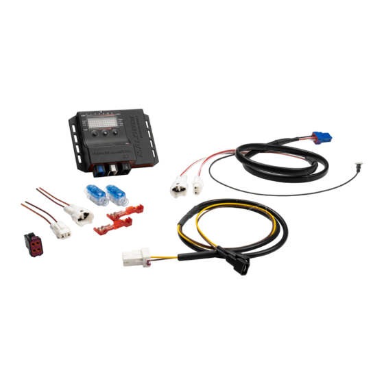
Page 19: Control Unit Set-Up
Plug the cables into the relevant engine, taking care that they are connectors, which can be easily not damaged. identified thanks to the colours. • Place the Force Master 2.1 control... - Page 20 (Fig. • Connect the black cable (negative NB: pay attention to use the pole) coming out of the Malossi FEMALE faston!!! control unit to the screw of the • Close the joint using a pliers, such variator cover (Fig.
- Page 21 • Make the following connections using the cable clamp: » Yellow Malossi control module cable with orange/white TPS cable » Brown Malossi control module cable with black/green TPS...
-
Page 22: Tps Calibration
Working Control module status display • “-” e “+” buttons: only active in The control unit display shows the certain operating modes, they allow status it is in, showing both the to increase or decrease the value functionality of the engine when selected in the different functions switched on and any possible errors or supporting the user if the buttons... - Page 23 • If calibration successful, “OK” • The display shows the maximum appears calibration logo flashing • If calibration was unsuccessful, the • If calibration successful, “OK” message “OUT OF RANGE” appears appears and it is necessary to repeat the • If calibration was unsuccessful, the operation, checking that the message “OUT OF RANGE”...
-
Page 24: Map Selection
MAP selection Working (Fig. 7) “Maps”: The active map is displayed These adjustments can be carried with the word “M” followed by the out with the engine running, in map number and a different map ventilated places. can be selected using the “-” and “+” buttons. - Page 25 a few seconds of inactivity The “-” and “+” buttons reduce or it returns to the engine increase the injection correction screen display. in 2% steps in the relevant RPM The “-” and “+” buttons reduce or ranges. When these buttons are increase the injection correction pressed, the selected correction in 2% steps in the relevant RPM...
- Page 26 range. When these buttons are the right-hand side of the display, pressed, the selected correction while showing the map about to flashes. To confirm the selected be activated in flashing mode on correction, it is necessary to wait the left. To activate the map, wait for the end of the flashing.
- Page 27 Diag shows “NO ERROR”. If the engine The Force Master 2.1 control unit is is switched on, after displaying equipped with a display that shows the complete sequence of all possible diagnostic messages: information, it returns the engine screen display returns, otherwise •...
- Page 28 protection mode and injection is • “TUNING TPS” - TIncorrect not implemented. throttle calibration (for vehicles The control unit must be switched where TPS calibration is required) off and on again to allow the vehicle The throttle calibration procedure to start. If the error persists, it is was not carried out correctly by the essential for the operator to check user and must be repeated.
- Page 29 lean or too rich. • “IGN LOST” - No coil connected If the error persists, it is imperative The connection to the coil for the operator to check the is missing. connection to the throttle cable. The control unit may be restricted in injection and is not injecting after •...
-
Page 30: Normal Operation
normally but problems may arise in • “VBATT LOW” - Battery voltage the general operation. too low The operator must make The battery voltage has been below appropriate checks on the system 11V for at least 10 seconds. because this problem cannot be The control unit is behaving caused by the control unit. -
Page 31: Technical Details
• Environmental protection = IP65 interrogate the control unit by going to the specific function to find out Maps the error. The Force Master 2.1 CDI is programmed with 4 base fuel curves: Technical details • curva 0 (125cc vehicles): original • Carburation adjusting exhaust system, Malossi cylinder, •... - Page 32 • curva 0 (150cc vehicles): Malossi exhaust system with DB killer, Malossi cylinder, original head, original camshaft, original filter...
-
Page 33: Warranty
So goodbye from us all at Malossi, and please accept our Warranty compliments. Have Fun. GOOD LUCK and … see you next time. - Page 34 These products are reserved solely for races in locations reserved for those purposes and in accordance with the regulations issued by the competent authorities for sports events. We decline any and all responsibility for improper use.
- Page 35 Fig. 1...
- Page 36 Fig. 2...
- Page 37 Fig. 3 Rosso/verde Rosso/nero Red/green Red/black Rosso/giallo Arancione/nero Red/yellow Orange/black...
- Page 38 Fig. 4...
- Page 39 Fig. 5...
- Page 40 Fig. 6...
- Page 41 Fig. 7 Centralina Coppia connettori iniettori Injector connectors pair Tappo Occhiello di massa Ground ring terminal Connettore TPS TPS connector...
- Page 42 Fig. 9 Fig. 8 Fig. 10 Fig. 11...
- Page 43 Fig. 13 Fig. 12 Fig. 14 Fig. 15...
- Page 44 Fig. 16 Fig. 17...
- Page 46 01/2023 - 7319463 FORCE MASTER 2.1 Accensioni - Centraline Ignitions - Controllers Our Ignition - Controllers Univers Inquadra qui per altre lingue For more languages view here Voir ici pour d’autres langues Sehen Sie hier für andere Sprachen Ver aquí para otros idiomas...
Need help?
Do you have a question about the FORCE MASTER 2.1 and is the answer not in the manual?
Questions and answers