Table of Contents
Advertisement
Quick Links
Advertisement
Table of Contents

Related Manuals for Gravely HR1536FL


Summary of Contents for Gravely HR1536FL
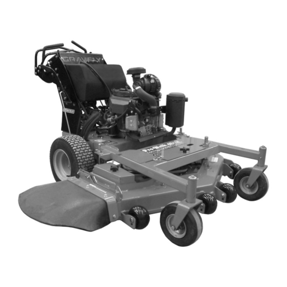
- Page 1 Pro-Walk Hydro Owner/Operator Manual Manuel Du Propriétaire/Utilisateur Models 988146 – HR1536FL 988147 – HE1948FL 988148 – HE1952FL Serial numbers 401 and higher. Numéros de série 401 et supérieur. ENGLISH 03990200A 2/10 Printed in USA FRANÇAIS...
-
Page 2: Table Of Contents
English may be obtained from your and completely read your manuals. The Dealer. Visit your dealer or contents will provide you with an www.gravely.com for a list of understanding of safety instructions and languages available for your controls during normal operation and maintenance. - Page 3 Gravely authorized replacement part may adversely affect the performance, durability, or safety of this unit and may void the warranty. Gravely disclaims liability for any claims or damages, whether warranty, property damage, personal injury or death arising out of the use of unauthorized replacement parts.
-
Page 4: Safety
SAFETY CAUTION: POTENTIALLY WARNING: This cutting unit is HAZARDOUS SITUATION! If not capable of amputating hands and avoided, MAY RESULT in minor or feet and throwing objects. Failure moderate injury. It may also be to observe the safety instructions used to alert against unsafe in the manuals and on decals practices. - Page 5 • Keep safety devices (guards, shields, 988146 switches, etc.) in place and working. • Check interlock system per manual before use. • Never allow operation by untrained persons. • When parking on a slope always engage parking brake. • Disengage PTO, stop unit and engine, set parking brake and remove key before making any inspections, repairs, etc.
- Page 6 4. WARNING! NEVER operate unit after or during the use of medication, drugs or alcohol. Safe operation requires your complete and unimpaired To avoid injury from tipover, drive attention at all times. across slopes, not up and down. If machine stops going uphill, stop NEVER allow anyone to operate this unit blades and back down slowly.
- Page 7 ALWAYS keep protective structures, guards, Turf conditions can affect the unit’s stability. and panels in good repair, in place and Keep all movement on slopes slow and securely fastened. gradual. DO NOT make sudden changes in NEVER modify or remove safety devices. speed or direction.
- Page 8 Avoid Electric Shock. Objects contacting both An extension spring, when extended, stores battery terminals at the same time may result energy and can be dangerous. Always use in injury and unit damage. DO NOT reverse tools specifically designed for installing or battery connections.
-
Page 9: Assembly
ASSEMBLY Check Engine Oil Level Check Tire Pressure 1. Remove dipstick from tube by unscrewing it. Wipe it clean. CAUTION: Avoid injury! 2. Install dipstick and allow the cap to rest Explosive separation of tire and on the end of the tube. Do not tighten rim parts is possible when they the cap. -
Page 10: Operation
OPERATION DAILY OPERATING CHECKLIST Check engine and hydraulic oil levels. Remove mower deck belt shields. Clean grass and debris from belt Inspect all belts for damage or area. cracking. Remove grass and debris from Inspect engine air filter. machine and mower deck. Inspect mower level. -
Page 11: Controls And Features
CONTROLS AND FEATURES Figure 5 1. Throttle Lever 2. Choke Control 3. Fuel Fill 4. Hydraulic Oil Reservoir Fill 5. Power Take Off (PTO) Switch 6. Ignition Switch 7. Control Height Knob (2 used) 8. Right Control Lever 9. Speed Control/Safety Bar 10. - Page 12 Ignition Switch TEST SAFETY SYSTEMS Operate the ignition switch with the CAUTION: Avoid injury! Engine removable key. exhaust fumes contain carbon 988147, 148: The monoxide and can cause serious illness or death. switch has three positions: STOP (1), Move the unit to an outside area Run (2) and Start (3) before running the engine.
- Page 13 4. Turn the key to the ON position. Turn 2. Engage parking brake. ignition key to the START position and 3. Move PTO/clutch switch to OFF release (988147, 148) or pull recoil position. starter (988146). 4. Move throttle lever to half-speed Result: The engine must not start.
- Page 14 To drive the unit forward: Push both control Emergency Stop levers (A) forward smoothly and evenly. To stop blades and unit drive in an To turn the unit: Pull the control lever back emergency, release operator presence on the same side as the direction of the control lever.
- Page 15 Adjusting Cutting Height Cutting height can be adjusted from 1-1/2 – 4-1/4 in. (38 – 108 mm) using the height of cut (HOC) rods and washers supplied with the unit. NOTE: If necessary, up to an additional 3/4 in. (19 mm) of cutting height can be obtained. See Additional Cutting Height on page 16.
- Page 16 HEIGHT OF CUT – FLOAT DECK PRO WALKS HOC Rod Cut Height Hair Pin Washer Inch (mm) Position 1.5 (38) 1.75 (44) 2.0 (51) 2.25 (57) 2.5 (64) 2.75 (70) 3.0 (76) 3.25 (83) 3.5 (90) Position 3.75 (95) 4.0 (102) 4.25 (108) For HOC over 4.25 in.
-
Page 17: Maintenance
Desired Cut Number of Blade Bolt Height – Spacers on Spindle In. (mm) 4.5 (114) Standard 4.75 (121) Short 5.0 (127) Short 4. Replace the mower blades. IMPORTANT: Ensure that all mower blades are mounted with the same number of spacers. - Page 18 • Apply grease to front caster wheels. • Apply grease to front caster wheel spindles. • Remove debris from the underside of the mower deck. • Check drive belt tension. • Check tire pressure. • Clean engine air filter. • Check wheel nut torque.
- Page 19 ENGINE SERVICE 988146 Avoid Fumes CAUTION: Avoid injury! Engine exhaust fumes contain carbon monoxide and can cause serious illness or death. Move the unit to an outside area before running the engine. Do not run an engine in an enclosed area without adequate ventilation.
- Page 20 Clean Air Intake Screen and Engine Fins IMPORTANT: Avoid damage! The engine is air-cooled and requires a large amount of air intake when running. Reduced air intake can cause overheating: • Keep air intake screen and cooling fins clean. • Keep covers and screens in place.
- Page 21 Replacing Fuel Filter SERVICING TRANSMISSION Avoid Fumes CAUTION: Avoid injury! Fuel vapors are explosive and flammable: CAUTION: Avoid injury! Engine • Do not smoke while handling exhaust fumes contain carbon fuel. monoxide and can cause serious • Keep fuel away from flames illness or death.
- Page 22 Figure 20 6. Apply a film of clean oil to gasket of new filter. 7. Install filter. Turn filter clockwise until gasket makes contact with the mounting Figure 21 surface. Tighten 1/2 to 3/4 turn after contact. 6. If wheels continue to rotate, adjustment 8.
- Page 23 Adjusting Tracking CAUTION: Avoid injury! Clear area of all bystanders before performing this service procedure. 1. Park unit safely. See Using the Parking Brake on page 13. 2. Start and run engine until it reaches normal operating temperature. 3. Move unit to an open area for operation. 4.
- Page 24 988146 B, C 988147, 148 Figure 26 6. Remove traction drive belt (E). Installation Figure 27 1. Install new traction drive belt (E). 2. Connect tension spring (D) to idler pulley Removing and Installing Mower Deck bolt (C). Install nut (B) and tighten until 1-2 threads of bolt are visible.
- Page 25 5. Remove mower deck drive belt and IMPORTANT: CHECK AND ADJUST discard. MOWER DECK DRIVE BELT AFTER 5 HOURS OF OPERATION. 6. Install new mower deck drive belt. See Figure 28 for belt routing. Adjusting Mower Deck Rake 7. Tighten nyloc hex nut on top of pulley. NOTE: The rear-to-front deck rake is pre-set 8.
- Page 26 Checking for Bent Mower Blades 2. Secure blades with a wooden block to prevent blade rotation. 3. Tighten blade bolts to a torque of 120 CAUTION: Avoid injury! Mower lbf-ft (163 N•m). blades are sharp. Always wear 4. Replace ignition wires on spark plugs. gloves when handling mower blades or working near blades.
- Page 27 Balancing Blades CAUTION: DO NOT sharpen mower blades while on unit. An CAUTION: Avoid injury! Mower unbalanced mower blade will blades are sharp. Always wear cause excessive vibration and gloves when handling mower eventual damage to unit. Check blades or working near blades. mower blade balance before reinstalling blades.
- Page 28 12. If removed, install mower blade, blade spacers and blade bolt. See Replacing Mower Blades on page 26. Replacing Mower Deck Idler Pulley NOTE: It is not necessary to remove spring pressure to remove the idler pulley. 1. Park unit safely. See Using the Parking Brake on page 13.
- Page 29 ELECTRICAL SERVICE (988147, CAUTION: Avoid damage! The 148) battery comes fully charged. If the unit is not used by the service WARNING: Battery posts, expiration date indicated on the terminals and related accessories battery, charge the battery. contain lead and lead components, chemicals known to If charging is necessary, follow battery the State of California to cause...
- Page 30 Battery on page 30). and install cover (A). Jump-Starting Cleaning Battery and Terminals Gravely does not recommend jump-starting 1. Park unit safely. See Using the Parking your unit. Jump-starting can damage engine Brake on page 13. and electrical system components. See the 2.
- Page 31 Replacing Relays (988147, 148) NOTE: Relays are interchangeable. Use only quality replacement relays (see SERVICE PARTS on page 38). The unit is equipped with four relays located under the control panel area. 1. Remove defective relay from socket. 2. Install new relay into socket. Figure 41 5.
- Page 32 Using Proper Fuel 2. Raise and securely support the front of the mower. Use regular grade unleaded fuel with an 3. Remove nut (A), hex bolt (B) and wheel octane rating of 87 octane or higher. Fuel assembly (C). blends containing up to 10% ethanol or up to 4.
- Page 33 Figure 43 6. Install new bushings (D). Ensure that bushings are fully seated in weldment. 7. Install caster yoke/wheel assembly (E), washer (C), lock washer (B) and hex bolt (A). 8. Apply grease to lubrication fitting (F). Checking Rear Wheel Lug Nuts Tighten rear wheel lug nuts in an alternating pattern to 55 lbf-ft (75 N•m).
-
Page 34: Troubleshooting
TROUBLESHOOTING Engine Problem Probable Cause Engine Will Not Start or Is Hard to Control levers not in the neutral position. Start Key switch not in proper position. PTO engaged. Stale or improper fuel/fuel level. Plugged fuel filter. Plugged air intake filter. Spark plug wire is loose or disconnected. - Page 35 Hydraulic oil cold - allow engine to warm. Pump drive belt slipping. Pump bypass valves open. Pump drive belt damaged or worn. Wheel motor problems. See your Gravely dealer. Unit Creeps With Engine Needs control linkage adjustment. Running and Control Levers in a...
- Page 36 Steering Problem Probable Cause Steering Not Working Parking brake locked. Pump bypass valves partially open. Improper tire inflation. Hydrostatic transmission oil low. Traction drive belt slipping. Traction drive belt damaged or worn. Unit Will Not Follow a Straight Steering linkage out of adjustment. Path Unit Moves to the Left or Right Pump linkage (neutral position) out of adjustment.
- Page 37 Sharpen and balance blades. Remove belt shields and check for debris on sheaves. Check sheaves for proper alignment or damage. See your Gravely dealer. Mower Blades Do Not Engage Mower deck drive belt slipping or broken. Spindle drive belt slipping or broken.
-
Page 38: Storage
GDU10231 Mower Blade (988146) To treat the fuel system for storage: GDU10230 Mower Blade (988147) Add fuel stabilizer (Gravely p/n 00592900) GDU10231 Mower Blade (988148) according to manufacturers’ instructions. Run engine for at least 10 minutes after adding stabilizer to allow it to reach the carburetor. -
Page 39: Specifications
SPECIFICATIONS Model Number 988146 988147 988148 Description HR1536FL HE1948FL HE1952FL Engine Kawasaki Kawasaki FH580V FH430V Displacement – in. (cc) Starter Recoil Electric Fuel See Engine Manual Tank Capacity – Gallons (Liters) 6.6 (25) Hydraulic System Capacity Completely Dry System – Qt. (Liters) 5 (4.7) -
Page 40: Warranty
Genuine Ariens or Gravely brand service parts and accessories are warranted to be free from defects in material and workmanship for a period of 90 days after the date of purchase. An authorized Ariens or Gravely dealer will repair or replace any such part or accessory free of charge, except for labor, during that period. - Page 41 Engines and engine accessories are covered only by the engine manufacturer’s warranty and are not covered by this warranty. • Parts that are not genuine Ariens or Gravely service parts are not covered by this warranty. • The following maintenance, service and replacement items are not covered by this warranty unless...
- Page 42 GRAVELY 655 West Ryan Street Brillion, WI 54110-1072 920-756-2141 Fax 920-756-2407 www.gravely.com WARNING The engine exhaust from this product contains chemicals known to the State of California to cause cancer, birth defects or other reproductive harm.
Need help?
Do you have a question about the HR1536FL and is the answer not in the manual?
Questions and answers