Advertisement
Quick Links
Advertisement

Subscribe to Our Youtube Channel
Related Manuals for i-CAT FLX


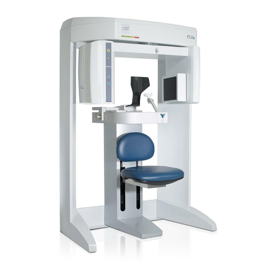
Summary of Contents for i-CAT FLX
- Page 1 Installation Training I-6800-39...
- Page 2 Installing the FLX • There are two methods used for shipping the unit, assembled and non- assembled. • We will focus on the non-assembled method first.
- Page 3 Non-assembled Setup 1. With the help of an assistant, install the 2. Attach with mounting hardware, four SHCS lower plate under the two leg assemblies, as 1/4-20 x 5 long with1/4” split washers, both shown. sides.
- Page 4 3. Remove both top covers (six mounting 4. With an assistant, lift overhead into place screws). on top of leg assemblies. WARNING This scanner requires a two person lift. Failure to comply may cause bodily injury. Two adults are required to assemble this scanner.
- Page 5 5. Ensure the pins on rear of the overhead are 6. When seated properly, overhead locks into seated into the holes on leg assemblies. place. To ensure safety, the overhead should still be supported by an assistant until mounted.
- Page 6 7. From rear of scanner, secure overhead with mounting hardware, two SHCS1/4-20 x 5/8 long with 1/4” split washers, both sides.
- Page 7 8.The scanner must be checked for square, prior to installing the mounting hardware at the top of the overhead. 9.Hook a tape-measure on bottom rear edge of scanner, as shown. 10.Run the tape diagonally to the upper open corner, as shown and record the measurement.
- Page 8 12. From top of scanner, secure overhead with mounting hardware, two SHCS 1/4-20 x 5/8 long with 1/4” split washers, both sides.
- Page 9 Assembled Setup 13. With the help of an assistant, tilt the 15. Position patient chair on gantry base. scanner to install the glides under the four Ensure base frame centering screw is seated feet (corners of scanner). within patient chair centering block. 14.
- Page 10 17. Remove four long screws from red shipping plate. Keep shipping plate attached with remaining hardware. • discard mounting hardware. Long screws used for receptor assembly mounting and short screws for source assembly.
- Page 11 18. Locate receptor assembly and remove 20. With an assistant, mount the receptor packing material. assembly by aligning the mounting pins. 19. Remove assembly cover from scanner (2 21. Attach assembly with four long mounting screws). screws acquired from red shipping plate. Once secured, remove remaining screws from shipping plate and save for later use.
- Page 12 23. Feed gray wire with red/white connector through brackets and connect to other red/white connector. 24. Feed second gray wire through brackets and connect the red/black wires with white connectors. 25. Connect together the green/yellow ground wires.
- Page 13 26. Connect grey wire with green connector to assembly. Run wire behind motor as shown.
- Page 14 27. Unlatch panel cover by pulling cover forward slightly, then swinging cover outward to remove. 28. Feed LEMO connector through hub and plug into panel. Rotate red dot on connector to the 3 o’clock position. Slide connector into receptor until it snaps in place.
- Page 15 33. Locate X-ray source assembly and remove 30. Snap receptor panel cover into place. from packing material. 31. Install receptor assembly cover. 34. Place assembly on clean surface. Remove Ensure mounting tabs are seated in top and set aside the magnetic mounted X-Ray of cover.
- Page 16 36. Detach outer cover ONLY. 37. Carefully detach and move inner source cover a few inches away from assembly. 38. Remove ribbon cable from beam limiter assembly by pressing connector locking tab.
- Page 17 39. Using very little force, slowly rotate gantry, counterclockwise. Stop the rotation when you feel that the gantry is at the limit switch position. 40. Slide inner source cover onto the gantry overhead.
- Page 18 41. With an assistant, align X-ray source assembly mounting pins. 42.Attach assembly using the four mounting screws previously removed from red shipping plate along with four split washers. 43.Draw the 3 cables out through the opening. Ensure that the cables are not stretched or damaged.
- Page 19 45. Attach ground lug by removing mounting nut and installing lug over the star-lock washer. Replace mounting nut. 46. Attach together, black cables with the two connectors. 47. Attach grey wire with red/white connector as shown. Ensure red side of connector is facing upward.
- Page 20 48. Attach ribbon cable back to the beam 49. Slide inner source cover into place, limiter assembly. onto top mounting notches. 50. Mount outer cover onto mounting notches, over panel cover. 51. Attach covers with hex mounting screws at top and bottom (quantity 4 outer cover and 4 inner source cover).
- Page 21 52. Obtain mounting bar assembly. 53.Install mounting bar on wall, centered behind the scanner. The height should be approximately 66.5 to 68 inches [169 to 173 cm] from the floor to the center of the mounting bar. 54. Use 3 wall anchors/screws to mount the bar securely to the wall.
- Page 22 56. Connect chair control cable to 1520 (Chair) connector on rear of overhead panel. 57. Connect control box cable to 1518 (Control Box) connector on rear of overhead panel. Connectors are keyed to prevent improper insertion. For wall mounting options, see Wall Mount Control Box chapter.
- Page 23 60. Connect chair control cable to patient 62. Connect power cable to AC POWER IN chair connecter. connector on rear of overhead panel. 61. Connect patient emergency stop control to 63. Ensure the power circuit breaker on the patient chair connector. Connectors are keyed overhead rear panel is set to the 0 (off) to prevent improper insertion.
- Page 24 64.Connect power cable to hospital grade receptacle. 65. To ensure that the device cabling does not interfere with the rotation of the gantry, use Cable Clips to dress cabling as shown.
- Page 25 CAUTION To assure proper Ethernet communications (1 GB) between the i-CAT scanner controller and the scanner, connect the Ethernet cable from the scanner controller directly to the scanner. Do not connect the Ethernet cable from the scanner controller to the scanner through the use of wall...
-
Page 27: Level Gantry
Level Gantry To achieve optimal performance, it is imperative that the gantry be properly leveled. 1. Scanner must be leveled from side-to-side and front-to-back. - Page 28 2. Level overhead gear by manually 3. Adjust the rear gantry feet using the adjusting the front gantry feet. 1/2” open-ended wrench. NOTE: Ensure levelness of overhead gear is measured front-to-back and side-to- side.
- Page 29 4. Store red shipping bracket in 5. Replace shielding cover. overhead.
- Page 30 6. Replace top cover (6 screws). 8. Switch the power circuit breaker located on the overhead rear panel to l 7. Now that the scanner is positioned (on). and leveled, tighten wall bracket at top rear of gantry.
- Page 31 9. Press the control box ON button. The scanner is now powered. 10. Power on the scanner controller (power button in front) and touch screen (power button on right side). NOTE: If at any time the Ethernet cable connecting the scanner to the scanner controller becomes disconnected, reconnect the cable and cycle the power to the scanner from the circuit breaker at the rear of the scanner overhead.
- Page 32 Physical Installation Complete...
Need help?
Do you have a question about the FLX and is the answer not in the manual?
Questions and answers