
Related Manuals for i-CAT FLX V Series


Summary of Contents for i-CAT FLX V Series
- Page 1 C o n e B e a m 3 D + 2 D P a n o r a m i c D e n t a l I m a g i n g S y s t e m T e c h n i c al G u i d e...
- Page 2 Copyright © Dental Imaging Technologies Corporation 2013 - 2016 This manual contains original instructions by Dental Imaging Technologies Corporation for the safe use of the i-CAT FLX imaging system and were originally drafted, approved and supplied in English. Dental Imaging Technologies Corporation reserves the right to make changes to both this manual and to the products it describes.
-
Page 3: Table Of Contents
ABLE OF ONTENTS Chapter 1 - Introduction i-CAT FLX V-Series Imaging System Description ............1-1 Operator Control Box ...................... 1-2 Patient Emergency Stop Control ..................1-3 Software Description ....................1-3 SmartScan STUDIO Software ..................1-3 TxSTUDIO Treatment Planning Software ............... 1-3 System Requirements .................... - Page 4 FLX Technical Guide QA Line Pair Test ....................... 3-5 Setup QA Phantom ......................3-5 Run QA Line Pair Test ..................... 3-6 QA Line Pair Evaluation ....................3-7 Distance Measurement Test .................... 3-9 QA Material Test ...................... 3-10 Set Up QA Phantom ...................... 3-10 Run QA Material Test ....................
- Page 5 Table of Contents Chapter 5 - Data Utilities Introduction ......................... 5-1 Data Utility ........................5-1 Install and Configure Data Utility ..................5-2 Using the Data Utility ....................... 5-3 Export Database to DEXIS Core ..................5-9 Patient Data Utility ...................... 5-9 Install and Configure Patient Data Utility ...............
- Page 6 FLX Technical Guide Patient Support Chair ....................B-5 Environmental Specifications ..................B-5 Operating .........................B-5 Transportation and Storage .....................B-5 Labels ......................... B-6 Proper Disposal of Electronic Equipment ..............B-16 Product Disposal ......................B-16 Passing the Product on to Another User ...............B-17 Scanner Dimensions ....................
-
Page 7: Chapter 1 - Introduction
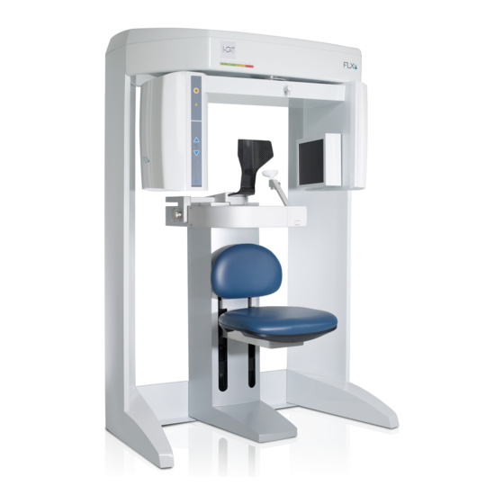
Chapter i-CAT FLX V-Series Imaging System Description The i-CAT FLX is a Cone Beam Volumetric Tomography and Panoramic imaging system used for dental head and neck applications. It consists of a scanner, scanner controller, touch screen and keyboard which is suitable for an in-office environment. -
Page 8: Operator Control Box
FLX Technical Guide The scanner is an open design that allows patients to sit upright during a procedure. An electric powered seat is built into the scanner for proper patient positioning. The scanner captures data for 3D skull reconstruction for the following procedures: •... -
Page 9: Patient Emergency Stop Control
TxSTUDIO Treatment Planning Software TxSTUDIO treatment planning software reconstructs 3D volume rendering from images acquired on the i-CAT FLX imaging system.TxSTUDIO is offered for exclusive use with the i- CAT imaging system, which is manufactured by Imaging Sciences. TxSTUDIO may not be available in all regions. - Page 10 FLX Technical Guide Operating Server Only: System Windows ® 7 Professional, Ultimate, and Enterprise (64-bit) SP1 Windows 8.1 Pro and Enterprise (64-bit) ® Windows ® 10 Pro and Enterprise (64-bit) Windows Server 2008 R2 SP1 ® Windows ® Server 2012 (all versions)
-
Page 11: Chapter 2 - Startup And Shutdown
To log in to SmartScan STUDIO on the scanner controller: 1. Enter your user name and password. 2. Press to log in. NOTE: Refer to the i-CAT FLX User Manual for information about using SmartScan STUDIO for the scanning workflow. 032-0328-EN Rev K... -
Page 12: Scanner Shutdown
FLX Technical Guide Scanner Shutdown Log out 1. Press . This button is accessible from Scheduled Exams or at the conclusion of the scanning workflow. 2. On the logout confirmation dialog, press to close exam and log out. 3. Depending on your account type, either the User menu or the Administrator menu is displayed. -
Page 13: Chapter 3 - Calibrations And Quality Assurance
Options for running scanner tests are available on the Utilities menu. From SmartScan STUDIO scanning workflow, press to access the Utilities menu. NOTE: Refer to the i-CAT FLX User Manual for information about using SmartScan STUDIO for the scanning workflow. Option... -
Page 14: Panel Calibration
FLX Technical Guide CAUTION If the optional deadman handswitch is installed on the scanner, press and hold handswitch before pressing the Scan button, and continue to hold handswitch down for the duration of the exposure (X-ray light on). Early release of the handswitch stops the exposure and the Fault light turns on. -
Page 15: Shutter Calibration
Calibrations and Quality Assurance Shutter Calibration It is recommended that Shutter Calibration be performed once a week to ensure optimal image quality. This calibration is also necessary if a mechanical adjustment is made to the beam limiter or if image quality has degraded. ShutterCal runs several tests in both landscape and portrait (V17 systems only) positions. -
Page 16: Geometric Calibration
FLX Technical Guide Geometric Calibration It is recommended that Geometric Calibration be performed once a year to ensure optimal image quality or if the image quality is degraded. GeoCal runs in both portrait (V17 systems only) and landscape positions. A pie chart displays status. -
Page 17: Qa Line Pair Test
Calibrations and Quality Assurance 8. Press to display Complete screen and select another option. QA Line Pair Test Setup QA Phantom 1. Remove chin cup and insert phantom platform. 2. Place QA phantom on platform. Use a piece of foam beneath the phantom to elevate it. Make sure phantom is level. -
Page 18: Run Qa Line Pair Test
FLX Technical Guide Make sure the phantom is centered left to right and front to back. Use the lasers to confirm. Horizontal Laser Line through Center of Phantom Run QA Line Pair Test 1. From Utilities menu, select QA Line Pair. -
Page 19: Qa Line Pair Evaluation
Calibrations and Quality Assurance 8. When prompted, press the Scan button on the operator control box. An audible alarm is sounded and the X-ray ON light is illuminated during radiation exposure. The scanner acquires data and a status indicator shows acquisition and image creation progress. - Page 20 FLX Technical Guide 5. Zoom upper left line pair image. To zoom, move the mouse cursor in the center of the image, hold down the Control key and press the left mouse button. Move the cursor up or down to zoom in or out as needed. To pan, move the mouse cursor in the center of the image, hold down the Shift key, press left mouse button and drag the image.
-
Page 21: Distance Measurement Test
Calibrations and Quality Assurance 9. Verify that definition is present within line pairs 10, 11, and 12. Compare image quality to the image shown. Distance Measurement Test To ensure measurement accuracy, this procedure checks Distance measurements. 1. Select to activate Distance tool. NOTE: To better view image, select to turn off cursor lines. -
Page 22: Qa Material Test
FLX Technical Guide QA Material Test Set Up QA Phantom Follow steps in Setup QA Phantom (page 3-5), if phantom is not already in place. Run QA Material Test 1. From Utilities menu, select QA Material. 2. Ensure phantom is set up properly, then press 3. -
Page 23: Qa Material Evaluation
Calibrations and Quality Assurance QA Material Evaluation 1. At a clinical workstation, start SmartScan STUDIO Manager and select Exam List. 2. On Exam List, locate QA 3D_2 Material exam with most current date. Double-click CT entry to load study in TxSTUDIO. NOTE: If a pop-up message displays stating “Tru-Pan failed to process”, click OK and continue. - Page 24 FLX Technical Guide 5. Zoom upper left image. To zoom, move the mouse cursor in the center of the image, hold down the Control key and press the left mouse button. Move the cursor up or down to zoom in or out as needed. To pan, move the mouse cursor in the center of the image, hold down the Shift key, press left mouse button and drag the image.
- Page 25 Calibrations and Quality Assurance 11. Record the Mean HU value of each material. See table below. Recorded values should fall within the lower and upper limits. Mean Scan Value Lower Upper Mean Material (Hounsfield Units) Limit Limit Air (Black) (lower left) -1000 -980 -990...
-
Page 26: Qa Air Water Test
FLX Technical Guide QA Air Water Test Set Up QA Air Water Phantom NOTE: It is important to use the water phantom provided with the scanner. Use distilled water in the phantom. Using tap water may negatively affect the test results. -
Page 27: Qa Air Water Test Evaluation
Calibrations and Quality Assurance The scanner acquires data and a status indicator shows acquisition and image creation progress. When image processing is complete, image is displayed. 9. Review image to ensure adequate quality. Press to display Complete screen and select option to go Back to Utility. QA Air Water Test Evaluation 1. - Page 28 FLX Technical Guide Noise Level Evaluation 5. Zoom upper left image. To zoom, move the mouse cursor in the center of the image, hold down the Control key and press the left mouse button. Move the cursor up or down to zoom in or out as needed.
- Page 29 Calibrations and Quality Assurance 9. Record the Water HU Mean value in the table below. 10. In the upper right image, slide the vertical and horizontal cursor lines above the water level. 3-17 032-0328-EN Rev K...
- Page 30 FLX Technical Guide 11. Record the Air HU Mean value in the table below. Recorded values should fall within the ranges. Measured Values Water Mean Expected Values 0 (-70 to +70) -1000 (-1000 to -950) 12. Remove measurement by clicking on it to select it, then press the Delete key on the keyboard.
- Page 31 Calibrations and Quality Assurance 16. Repeat steps 14-15 for the lower left, upper right and lower right quadrants, and at the center. 17. Record the Mean values in the chart below. 18. Remove measurements by clicking each one, then press the Delete key on the keyboard.
-
Page 32: Qa Pan Test
FLX Technical Guide QA PAN Test Install PAN Phantom 1. Prepare the bite tip by inserting the narrow edges of the bite tip down into the bite tip holder uprights. Then turn the bite tip a ¼ turn to lock into place. -
Page 33: Qa Pan Test Evaluation
Calibrations and Quality Assurance 4. When prompted, press the Scan button on the operator control box. An audible alarm is sounded and the X-ray ON light is illuminated during radiation exposure. 5. Review the scout image. Ensure the phantom is centered. Adjust the phantom platform as needed to achieve the proper height. -
Page 34: Radiation Output Test
FLX Technical Guide Radiation Output Test It is recommended that a check of the kVp(eff) and Radiation Output of the X-ray source be performed annually by a qualified Physicist. The incident Absorbed Dose at the detector may be measured using a dosimeter. Tests are performed to assess output value and to check for tube output consistency and timer accuracy. -
Page 35: Interpretation
Calibrations and Quality Assurance Interpretation 1. The dose per frame at the detector may be calculated by: Dose per frame at Detector = Dose at Detector / Number of Frames Where Number of Frames = 309 for 8.9 second scan = 619 for 26.9 second scan 2. - Page 36 FLX Technical Guide 3-24 032-0328-EN Rev K...
-
Page 37: Chapter 4 - Site Administration
Site Administration Chapter Site Administrator Account The Site Administrator login account provides access to additional functions for site administration. Option Purpose Add, edit or delete user accounts Configurator Add or enter institution name Enter or view network information Image data maintenance View and export dose logbook View and export activity log Technical Support... -
Page 38: Configurator
FLX Technical Guide Configurator 1. Select Configurator from menu. 2. To exit Configurator, press Accounts This option enables the system administrator to add, edit, or delete user accounts. Add Accounts Use this option to add a new user account. -
Page 39: Institution
Select Full network details to display information about Windows ® IP configuration, Ethernet adapter LAN connection, Ethernet adapter i-CAT (scanner) connection and Tunnel adapter. Maintenance Exam data is maintained on the scanner controller for a short period of time before it copied to remote storage (image server). -
Page 40: Dose Logbook
FLX Technical Guide Run Maintenance Now - Use this option to perform the scheduled routine maintenance immediately instead of at the regularly scheduled time. Dose LogBook Use this option to export the dose logbook for a selected patient or all patients. The dose logbook provides an itemized list of date, time, modality, and DAP values for each patient exposure. -
Page 41: Chapter 5 - Data Utilities
Data Utilities Chapter Introduction NOTE: DEXIS is optional software and is not available in all countries. Two data utilities are provided on the SmartScan STUDIO Server Installation media: • Data Utility - scans the patient database for conflicts with patient IDs and patient names. It provides options to move studies and edit patient data to resolve conflicts and export the studies to DEXIS. -
Page 42: Install And Configure Data Utility
The Data Utility also enables you to export patients and studies that were previously captured on an i-CAT FLX, i-CAT 17-19 or KaVo 3D eXam scanner to DEXIS Core. Additionally, you can display DICOM scans and scouts within the utility that were acquired on the FLX. Raw PAN images are not available for viewing in the utility. -
Page 43: Using The Data Utility
Data Utilities 9. On initial startup, a message is displayed indicating the image root location is not found. Click OK. 10. On the Data Utility window, click button and browse to the Image Root folder that contains the patient data to be edited. (Typically, this is ProgramData\Dental Imaging Technologies Corporation\ImageRoot.) 11. - Page 44 FLX Technical Guide 2. Review list for conflicts. Patient IDs that contain conflicts are displayed in red. Look for the following conditions: Patient data not identical for same patient. Identify if multiple patient files that • exist under a patient ID refer to the same patient. For example, if the patient first...
- Page 45 Data Utilities 3. Select the name of the patient from the list where the patient study is to be moved to. In the example below, the studies for patient “Smith, Jon” will be moved to patient “Smith, John A. Jr, Mr”. 4.
- Page 46 FLX Technical Guide 3. Complete the fields for patient ID, name and date of birth. In the example below, patient “Smith, Jon” and related studies will be moved to new patient ID “142”. 4. Click OK. The DICOM files are updated with the requested changes. A progress bar displays and changes are logged at the bottom of the window.
- Page 47 Data Utilities Change a Patient ID (Fix Keys) Use this procedure to change all patient data (patient name and date of birth) under a single patient ID to be the same for all studies under that ID. CAUTION Be sure that all studies under the patient ID are for the same patient. 1.
- Page 48 FLX Technical Guide View Study Images For Patient You can view thumbnail images for a specific patient study that were captured on the i-CAT FLX. 1. Click + next to patient’s name to expand the record and display the study entries.
-
Page 49: Export Database To Dexis Core
Changes will also be applied to the DEXIS patient database if the site is using DEXIS with SmartScan STUDIO. Additionally, you can display DICOM scans and scouts within the utility that were acquired on the i-CAT FLX. Raw PAN images are not available for viewing in the utility. 032-0328-EN Rev K... -
Page 50: Install And Configure Patient Data Utility
FLX Technical Guide Install and Configure Patient Data Utility NOTE: The Patient Data Utility should have been installed with SmartScan STUDIO Integration Services on the long-term data storage server. If it is not installed, follow steps 1 - 6 to install it. Otherwise, skip to step 7. -
Page 51: Using The Patient Data Utility
NOTE: You can view thumbnail images for a specific patient study that were captured on the i-CAT FLX. Click on an entry under Studies with the Modality of either Raw Volume or Volume to display the image. - Page 52 FLX Technical Guide 3. When changes are made, click Save. A dialog is displayed showing all fields in the DICOM data that will be changed. 4. Click OK to continue. The DICOM files are updated with the requested changes. A progress bar displays and changes are logged at the bottom of the window.
-
Page 53: Appendix A - Safety Information
Safety Information Appendix Important Safety Information Imaging Sciences designs its products to meet stringent safety standards. However, to maintain the safety of operators and patients, you must operate the equipment correctly and properly and ensure the equipment is properly maintained. It is essential to follow all safety instructions, warnings, and cautions specified in this manual to ensure the safety of patients and operators. - Page 54 FLX Technical Guide Viewing the laser output with certain optical instruments (for example, eye lopes, • magnifiers and microscopes) within a distance of 100 mm may pose an eye hazard. Viewing the laser output with certain optical instruments designed for use at a distance (for example, telescopes and Binoculars) may pose an eye hazard.
-
Page 55: Electrical Hazards
Safety Information Electrical Hazards Installation and scanner wiring must meet all requirements of local governing authorities. Please check your local authorities and local codes to determine best practices for a safe installation. Do not place any liquid or food on any part of the scanner controller or other modules of the scanner. -
Page 56: Tube Head Leakage
FLX Technical Guide If a collision occurs, the message A scanner stall was detected is displayed on the scanner controller. The dialog box instructs the operator to clear the patient environment. The operator should lower the chin support and remove the patient or other obstacles. When completed, the operator should press OK on the dialog box. -
Page 57: Radiation Protection Measures
Safety Information Radiation Protection Measures Use the following measures to protect yourself and the patient from unintended exposure to radiation. Anyone who is near the patient during test procedures must observe the following precautions: • Maintain adequate distance from exposed radiation source. •... -
Page 58: Interlock System
FLX Technical Guide Interlock System The scanner is equipped with provisions for a low voltage 12 volts DC interlock circuit which, when opened, will turn off X-ray power. The interlock circuit can be used for a door interlock switch, a deadman handswitch, or both. Use of the interlock circuit is optional based on site requirements. - Page 59 Safety Information NOTE: 1. Connection of the imaging system to the customer network/data coupling that includes other equipment could result in previously unidentified risks to patients, operators, or third parties. 2. The customer should identify, analyze, evaluate and control these risks. 3.
- Page 60 FLX Technical Guide 032-0328-EN Rev K...
-
Page 61: Appendix B - Product Information
User Proficiency The i-CAT is designed to be operated by healthcare professionals who are educated and competent in the techniques described in the accompanying documentation. Specific educational requirements are determined by state and/or national regulatory agencies. Operators are strongly... -
Page 62: Service
Radiological Protection and, in the United States, the US National Council for Radiological Protection. It is strongly recommended that all operators complete i-CAT training. Contact Customer Service to schedule a training session. Basic computer skills and understanding of the Microsoft ®... -
Page 63: Technical Specifications
Product Information Technical Specifications X-ray Source Tube Voltage: 120 kVp(eff) Tube Current: 3-7 mA Voltage Wave Shape: Constant Potential Focal Spot: Duty Cycle: Source to Sensor distance: 71.4 cm Source to Patient distance: 49.53 cm (center of rotation) NOTE: The patient must be properly positioned in the Head Support for each patient for all applications in order to have the focal spot to skin distance as large as possible. -
Page 64: Power Requirements
FLX Technical Guide Power Requirements The scanner uses facility power and requires a dedicated line. A surge protector is recommended. The scanner is suitable for continuous connection to a power supply in stand-by mode. Line Voltage: 100VAC, 115VAC, 200VAC or 230VAC (Factory Set) -
Page 65: Weight
Product Information Weight Total Weight: 510 lbs. (231.3 kg) Tube Head Pod: 35.5 lbs. (16.1 kg) Receptor Pod: 57 lbs. (25.9 kg) X-Ray Power Supply: 9 lbs. (4.1 kg) Patient Support Chair Overall dimensions: 72.4 cm x 61 cm x 109.2 cm Weight: 125 lbs (56.7 kg) Seat height adjustment: 35.65 cm to 73.7 cm Maximum patient weight: 400 lbs (181 kg) -
Page 66: Labels
FLX Technical Guide Labels The following labels are attached to the scanner or scanner components. Refer to Symbol Glossary (page D-1) for more information on symbols. Label Definition and Location Symbol Definition Patient Emergency Stop Panel Label Location: Can either be hung from the chair support mechanism or held in the patient’s hand. - Page 67 Product Information Label Definition and Location Symbol Definition CAUTION X-RAYS: TO BE OPERATED BY AUTHORIZED PERSONNEL. SEE OPERATING INSTRUCTIONS. WARNING Turns Unit On THIS X-RAY UNIT MAY BE DANGEROUS TO PATIENT AND OPERATOR UNLESS SAFE EXPOSURE FACTORS, OPERATING INSTRUCTIONS AND MAINTENANCE SCHEDULES ARE Turns Unit Off OBSERVED.
- Page 68 FLX Technical Guide Label Definition and Location Symbol Definition CAUTION: LASER RADIATION DO NOT STARE INTO BEAM <1mW 635nm CLASS II LASER PRODUCT Warning Location: X-Ray Source Laser CAUTION: LASER RADIATION DO NOT STARE INTO BEAM <1mW 670nm CLASS II LASER PRODUCT...
- Page 69 Product Information Label Definition and Location Symbol Definition PANEL ONLY TO BE REMOVED BY ISI TRAINED SERVICE PERSONNEL Location: Beam Limiter Panel Warning Patient Alignment Panel Location: X-Ray Source Assembly Laser Seat Height Adjustment 032-0328-EN Rev K...
- Page 70 FLX Technical Guide Label Definition and Location Symbol Definition Chair Warning Label MAXIMUM LIFTING CAPACITY < 182 KG (<400 LBS) Warning Location: Chair Assembly Maximum Lifting Capacity Chair Label WARNING PINCH POINT KEEP HANDS CLEAR Pinch Point Seat Weighs 6.8 KG (15 LBS)
- Page 71 Product Information Label Definition and Location Symbol Definition Gate Label WARNING PINCH POINT KEEP HANDS CLEAR Warning Location: Chair Gate Pinch Point B-11 032-0328-EN Rev K...
- Page 72 FLX Technical Guide Label Definition and Location Symbol Definition Rear Overhead Label Modes of Operation: Continuous & Intermittent Warning Location: Rear Overhead Electrical Hazard Complies With Type-B Body Non-Ionizing Radiation Not For General Waste Chair Cable Control Box Cable...
- Page 73 Product Information Label Definition and Location Symbol Definition Fuse Label Location: Rear Overhead Door Interlock X-Ray On Lamp X-Ray Supply Fuse X-Ray Power Supply Label MODES OF OPERATION: CONTINUOUS & INTERMITTENT COMPLIES WITH IEC 60601-2-7 AND IEC 60601-2-28 Continuous : Intermittent Location: X-Ray Power Supply B-13 032-0328-EN Rev K...
- Page 74 FLX Technical Guide Label Definition and Location Symbol Definition Capacitor Warning Label Capacitor Has >300VDC Wait 5 minutes for capacitor discharge before handling. Warning Location: X-Ray Power Supply Capacitor Caution Label DO NOT USE GROUNDED TEST EQUIPMENT ON THIS UNIT...
- Page 75 Product Information Label Definition and Location Symbol Definition CE/ETL Label Location: Leg Serial Labels Location: Leg Manufactured By Manufactured Date Model No. Serial No. Filtration Focal Spot Location: Tube Head Assembly and Packing Crate B-15 032-0328-EN Rev K...
-
Page 76: Proper Disposal Of Electronic Equipment
FLX Technical Guide Label Definition and Location Symbol Definition Do Not Use with i-CAT SCAN Only Use with i-PAN SCAN Location: PAN Head Holder Push to Release Label Location: PAN Head Holder Proper Disposal of Electronic Equipment CAUTION Do not dispose of any parts of this product with industrial or domestic waste. Incorrect disposal of any of these materials may lead to serious environmental pollution. -
Page 77: Passing The Product On To Another User
Product Information maintenance and training. Therefore products are designed and manufactured to comply with relevant guidelines for environmental protection. As long as the product is properly operated and maintained, it presents no environmental risks. However, the product may contain material, which could be harmful to the environment if disposed of incorrectly. -
Page 78: Scanner Dimensions
FLX Technical Guide Scanner Dimensions TOP VIEW FRONT VIEW B-18 032-0328-EN Rev K... -
Page 79: Preventive Maintenance Schedule - For Owner / User
Product Information Preventive Maintenance Schedule - for Owner / User Daily: Routine Dusting - all surfaces Monthly: Clean all surfaces and check for failed/faulty indicator lights. Yearly: Check for satisfactory image quality. NOTE: It is the responsibility of the user to insure that the equipment is maintained in compliance with the manufacturer’s recommended maintenance schedule. -
Page 80: Planned Maintenance - 12 Month Schedule
FLX Technical Guide Clean the equipment surfaces frequently, especially if corroding chemicals are present. Unless otherwise instructed, use a cloth moistened with warm water and mild soap and wipe all surfaces to remove surface dirt and marks. Do not use strong cleaners and solvents as these may damage the finish. -
Page 81: Replaceable Parts
Product Information Perform Chair Calibration Check Patient Chair Center Alignment Check Patient Chair Level Check Laser Alignments Check Centerline Alignment Check Crosshair Laser Inspect Tube Housing Components Certification Label Warning and Indicators Oil Leaks Physical Damage Scanner Mounting Stability Inspect Beam Limiting Device Physical Damage Certification Label Check/Inspect X-Ray Controller... -
Page 82: Supplemental Components
FLX Technical Guide Supplemental Components Patient E-stop Carbon Fiber Head Rest Part # 1304-0 Part # 27-0 Quantity: 1 Quantity: 1 Glide Head Restraint Band Part # 910-24 Part # 27-1 Quantity: 4 Quantity: 50 Tool Kit Velcro Head... - Page 83 Product Information Cable Clips Platform Assembly Part # 101-6 Part # 14-4-0 Quantity: 6 Quantity: 1 Chair Calibration Handswitch Fixture (optional) Part # 26-16 Part # 1.010.3959 Quantity: 1 Quantity: 1 Cord Retention Overhead Cord Bracket Bracket Part # 1.012.6471 Part # 1.012.5468 Quantity 1 Quantity 1...
-
Page 84: Pan Scan Components
FLX Technical Guide PAN Scan Components Bite Tip Holder PAN Head Holder Part # 980220 Part # 33-0 Quantity: 2 Quantity: 1 Position Bite Tip Alignment Tool Part # 26-15 Part # 33-19 Quantity: 25 Quantity: 1 Pan Phantom... -
Page 85: Equipment Standards
CAN/CSA STD C22.2 No. 60601-1 IEC 60601-1-3 IEC 60601-2-32 CAN/CSA STD C22.2 No. 601.1-M90 Complies with ME Equipment for Dental Extra-Oral Radiography i-CAT FLX IEC 60601-2-63:2012 Equipment Class Protection against electric shock: Class I Applied part has degree of protection against electric shock: Class B... -
Page 86: Manufacturer's Declaration
Portable and mobile RF communications equipment can effect Medical Electrical Equipment. The i-CAT FLX complies with EMC requirements when used with the cables and accessories supplied with the product. The use of accessories, transducers and cables other than those sold by ISI and specified as replacement parts for internal components, may result in increased emissions or decreased immunity of the i-CAT FLX. - Page 87 Do not connect any items or equipment to this scanner which are not part of the scanner. The i-CAT FLX should not be used adjacent to or stacked with other equipment. If • adjacent or stacked use is necessary, the i-CAT FLX should be observed to verify normal operation in the configuration in which it will be used.
- Page 88 FLX Technical Guide Guidance and Manufacturer’s Declaration - Electromagnetic Immunity i-CAT FLX is intended for use in the electromagnetic environment. The customer or the user of the i-CAT FLX should ensure that it is used in such an environment.
- Page 89 Product Information Guidance and Manufacturer’s Declaration - Electromagnetic Immunity i-CAT FLX is intended for use in the electromagnetic environment. The customer or the user of the i-CAT FLX should ensure that it is used in such an environment. Immunity Test...
- Page 90 FLX Technical Guide Guidance and Manufacturer’s Declaration - Electromagnetic Emissions i-CAT FLX is intended for use in the electromagnetic environment. The customer or the user of the i-CAT FLX should ensure that it is used in such an environment.
- Page 91 Product Information Guidance and Manufacturer’s Declaration - Electromagnetic Emissions i-CAT FLX is intended for use in the electromagnetic environment. The customer or the user of the i-CAT FLX should ensure that it is used in such an environment. Radiated RF...
- Page 92 FLX Technical Guide Recommended Separation Distances between Portable and Mobile RF Communications i-CAT FLX Equipment and the i-CAT FLX is intended for use in an electromagnetic environment in which radiated RF i-CAT FLX disturbances are controlled. The customer or the user of the...
-
Page 93: Acknowledgements
Product Information Acknowledgements SmartScan STUDIO software makes use of the following open source projects. Source code is available on request. Library Homepage License Product Name http://qt.digia.com/ LGPL v2.1 (http://www.gnu.org/licenses/lgpl-2.1.html) qt.gitorious.org/qt-solutions LGPL v2.1 Solutions (http://www.gnu.org/licenses/lgpl-2.1.html) www.zeromq.org LGPL v3 (http://www.gnu.org/copyleft/lesser.html) QJson qjson.sourceforge.net LGPL v2.1 (http://www.gnu.org/licenses/lgpl-2.1.html) jQuery... - Page 94 FLX Technical Guide Library Homepage License Product Name Firebird www.firebirdsql.org IPL (http://www.firebirdsql.org/en/interbase- public-license/) IDPL (http://www.firebirdsql.org/en/initial- developer-s-public-license-version-1-0/) openssl www.openssl.org openssl (http://www.openssl.org/source/license.html) B-34 032-0328-EN Rev K...
-
Page 95: Appendix C - Radiation Information
Radiation Information Appendix Recommended Operating Requirements Local agencies or government bodies or international standards may dictate requirements for installation of the scanner in order to protect personnel and the public from exposure from the radiological output of the scanner. Consult your local agencies, government bodies, or international standards for actual requirements which apply. -
Page 96: Scan Times And Settings
FLX Technical Guide Scan Times and Settings NOTE: Scan times and settings are preselected and fixed. Scan Time has no affect on electrical power output. Linearity of Radiation Output: <.025 COV Type Scan Time Exposure Time (seconds) (seconds) (mGy cm 3D Ceph 18.54... - Page 97 Radiation Information Mode: 16 D x 13 Standard Time (s): 8.9 scan / 3.7 beam Diameter: 16 mA: 5 kVp: 120 mAs: 18.54 Distance in Feet Exposure Exposure Exposure scans/wk scans/wk scans/wk μ μ [meter] (mR) R/mAs mR/wk mR/wk mR/wk Location 3 [0.91m] 0.470...
- Page 98 FLX Technical Guide Mode: 16 D x 13 Quick Scan Time (s): 4.8 scan / 2.0 beam Diameter: 16 mA: 5 kVp: 120 mAs: 10.11 Distance in Feet Exposure Exposure Exposure scans/wk scans/wk scans/wk μ μ [meter] (mR) R/mAs...
- Page 99 Radiation Information Mode: 16 D x 13 Quick Scan+ Time (s): 4.8 scan / 2.0 beam Diameter: 16 mA: 3 kVp: 90 mAs: 6.1 Distance in Feet Exposure Exposure Exposure scans/wk scans/wk scans/wk μ μ [meter] (mR) R/mAs mR/wk mR/wk mR/wk Location 3 [0.91m]...
- Page 100 FLX Technical Guide Mode: 16 D x 13 Time (s): 26.9 scan / 7.4 beam Diameter: 16 mA: 5 kVp: 120 mAs: 37.07 Distance in Feet Exposure Exposure Exposure scans/wk scans/wk scans/wk μ μ [meter] (mR) R/mAs mR/wk mR/wk...
- Page 101 Radiation Information Mode: 16 D x 13 Quick Scan HD Time (s): 14.7 scan / 4.1 beam Diameter: 16 mA: 5 kVp: 120 mAs: 20.27 Distance in Feet Exposure Exposure Exposure scans/wk scans/wk scans/wk μ μ [meter] (mR) R/mAs mR/wk mR/wk mR/wk Location...
- Page 102 FLX Technical Guide Mode: 23 D x 17 Expanded - Standard Time (s): 8.9 scan / 3.7 beam Diameter: 23 mA: 5 kVp: 120 mAs: 18.54 Distance in Feet Exposure Exposure Exposure scans/wk scans/wk scans/wk μ μ [meter] (mR)
- Page 103 Radiation Information Mode: 23 D x 17 Expanded - Enhanced Time (s): 17.8 scan / 7.4 beam Diameter: 23 mA: 5 kVp: 120 mAs: 37.10 Distance in Feet Exposure Exposure Exposure scans/wk scans/wk scans/wk μ μ [meter] (mR) R/mAs mR/wk mR/wk mR/wk Location...
- Page 104 FLX Technical Guide Mode: 16 D x 13 Large Time (s): 20 scan / 20 beam Diameter: 16 mA: 5 kVp: 94 mAs: 100 Distance in Feet Exposure Exposure Exposure scans/wk scans/wk scans/wk μ μ [meter] (mR) R/mAs mR/wk...
-
Page 105: Dose And Sensitivity Profile
Radiation Information Dose and Sensitivity Profile The dose profile for the 16 and 23 cm scans were performed using a 0.3 mm solid state CT probe. Measurements were made at 0.5 and 1 cm intervals across the profile of the beam using an 8.9 second scan. - Page 106 FLX Technical Guide CTDI Free-air - Approximated a 100 mm CTDI from a free in air exposure. Included for reference only. Mid Scan Dose - A weighted dose estimate designed to approximate dose in a phantom from a single large width scan or a continuous helical scan. This may be a better measurement for approximating dose for CBCT.
-
Page 107: Detective Quantum Efficiency (Dqe
The following data regarding DQE versus spatial frequency as a function of dose is provided to allow the contribution of the i-CAT FLX imaging system to overall imaging performance matrix. The graph below shows a typical DQE for the 2520DX sensor panel as a function of spatial frequency, for a range of X-ray doses from 390 to 3500 nGy for a standard scan. -
Page 108: X-Ray Tube Assembly
FLX Technical Guide 61 nGy 341 nGy 667 nGy 1326 nGy 2110 nGy 3171 nGy X-ray Tube Assembly Nominal X-Ray Tube Voltage 120 kV Max. Tube Current 7 mA X-Ray Tube Nominal Anode Input Power 65 W X-Ray Tube Maximum Anode Heat Content... - Page 109 Radiation Information X-ray Tube Data X-ray Tube Type: SXR 130-15-0.5 Available focal spot size: 0.5 Available target angle: 15° Anode construction: Vacuum cast copper with tungsten target Cathode construction: Vacuum tube nickel with tungsten filament Max. Tube operating voltage: 130 kVp Full wave rectified RECEPTOR Inherent Filtration: 1.1 mm Al equivalent /...
- Page 110 FLX Technical Guide X-Ray Power Supply Tube Head Assembly Tested (no other additional accessories tested) 6 Pin Red Connector 1000-0 X-Ray Power Supply 1536 X-Ray Power 35-0 Tube Head 1535 Tube Head Cable Supply Cable 120V 10A supplied from a...
- Page 111 Radiation Information Target Angle to Specific Reference Axis 9.6 in (24.4cm) 28.1 in (71.4 cm) C-17 032-0328-EN Rev K...
- Page 112 FLX Technical Guide EMISSION CHARACTERISTICS (Full Wave Rectified, Single Phase, Bi-polar) 70 kVp 100 kVp 90 kVp 130 kVp TUBE CURRENT (mA) ANODE HEATING/COOLING CURVE FILAMENT VOLT/AMPS CHARACTERISTICS: 60 Hz AC & DC ANODE HEAT STORAGE CAP 30,000 H.U.
-
Page 113: Appendix D - Symbol Glossary
Symbol Glossary Appendix Symbol Title of Reference Standard Function/Description per Manufacturer Symbol Number Containing Standard Interpretation the Symbol Emergency 5638 IEC 60417 To identify an emergency Emergency Stop stop control device. Stop General W001 ISO 7010 To signify a general warning. General Warning Sign Warning... - Page 114 FLX Technical Guide Symbol Title of Reference Standard Function/Description per Manufacturer Symbol Number Containing Standard Interpretation the Symbol Ready (to 1140 ISO 7000 To indicate that the machine Ready operate) is ready for operation. Mass; weight 1321A ISO 7000 To indicate mass.
- Page 115 Symbol Glossary Symbol Title of Reference Standard Function/Description per Manufacturer Symbol Number Containing Standard Interpretation the Symbol “OFF” for a 5265 IEC 60417 To indicate the “OFF” Turns Unit Off part of condition for a part of equipment equipment, if the symbol 5008 cannot be used, for example, to identify the “OFF”...
- Page 116 FLX Technical Guide Symbol Title of Reference Standard Function/Description per Manufacturer Symbol Number Containing Standard Interpretation the Symbol Type B applied 5840 IEC 60417 To identify a type B applied Type B (Body) part part complying with IEC applied part 60601-1.
- Page 117 Symbol Glossary Symbol Title of Reference Standard Function/Description per Manufacturer Symbol Number Containing Standard Interpretation the Symbol Warning Cable Warning Cable Network Cable Network Cable to Workstation to Workstation Computer Computer Cable Cable Breaker Switch Breaker Switch On/Off On/Off Output 5035 IEC 60417 To identify an output terminal...
- Page 118 FLX Technical Guide Symbol Title of Reference Standard Function/Description per Manufacturer Symbol Number Containing Standard Interpretation the Symbol Catalogue 2493 ISO 7000 To identify the Model No. Number manufacturer’s catalogue number, for example on a medical device or the corresponding packaging.
- Page 119 Symbol Glossary Symbol Title of Reference Standard Function/Description per Manufacturer Symbol Number Containing Standard Interpretation the Symbol Continuous 6187 IEC 60417 To indicate that the laser Continuous operation equipment is set to a mode, where the exposure duration is limited by the operator actuating and releasing the footswitch.
- Page 120 FLX Technical Guide 032-0328-EN Rev K...
- Page 122 Manufactured by: Imaging Sciences International LLC 1910 North Penn Road Hatfield, PA 19440 USA Tel: 1-215-997-5666 Fax: 1-215-997-5665 032-0328-EN Rev K 2016 August 1...
Need help?
Do you have a question about the FLX V Series and is the answer not in the manual?
Questions and answers
how do you align the sagittal laser light Red with the patient midline ?it is off to the eye instead of the nose
To align the sagittal laser light on the i-CAT FLX V Series with the patient's midline:
1. Seat the patient with an erect posture and stretch the neck upward to avoid the spine interfering with the view.
2. Adjust the chair height so the patient's chin is on the chin rest while maintaining an erect posture.
3. Tilt the patient's head downward so the occlusal plane forms a 5° to 10° angle to the horizontal laser.
4. Use the sagittal laser (the front center laser) to ensure the patient is centered and facing straight forward.
This answer is automatically generated
Can I get a Chin Rest Part # 9140-0026-0006