Table of Contents
Advertisement
Quick Links
Marconi
Instruments
Marconi Moisture Meter
Moisture content measured to within 0.5% in a few
seconds.
Calibrations available for more than 200 different
substances.
Supplied with optional ISO or standard wheat and
barley scales.
Quick-loading compression cell eliminates packing
errors.
Compact, portable and battery operation.
Calibration check facility.
Model 933D
Instruction Manual
Advertisement
Table of Contents

Related Manuals for Marconi Instruments 933D


Summary of Contents for Marconi Instruments 933D
- Page 1 Marconi Instruments Marconi Moisture Meter Model 933D Moisture content measured to within 0.5% in a few seconds. Calibrations available for more than 200 different substances. Supplied with optional ISO or standard wheat and barley scales. Quick-loading compression cell eliminates packing errors.
- Page 2 No part of this book may be reproduced or transmitted in any form or by any mecms, electronic or mechanical, including photocopying, or recorded by any information storage or retrieval syston, without permission in writing by Marconi Instruments Ltd. Printed in the UK Manual part no. 46882-171 D Issue I Apr.
-
Page 3: Table Of Contents
EVEN HEADER CONTENTS Chapter I GENERAL INFORMATION 1.1 FEATURES. 1.2 DATA SUMMARY. 1.3 ACCESSORIES. Accessories supplied. Accessories available Chapter 2 OPERATION 2.1 Installation 2.2 Controls and connections. Balance controls Electrode connections ..Calculator scales ..2.3 PREPARATION OF SAMPLE. Granular or powdery substances .. -
Page 4: Chapter I General Information
Chapter 1 GENERAL INFORMATION 1.1 FEATURES The moisture meter measures the percentage moisture content of a wide range of hygroscopic materials, particularly those of organic origin, in the field or laboratory. The test cell which is of the compression type and is stowed in the instrument when not in use, is suitable for granular, powdery or fibrous substances and for specimens in the form of sheets or boards up to one inch in thickness. -
Page 5: Data Summary
GENERAL INFORMATION 1.2 DATA SUMMARY contents from below air-dry to near saturation. Moisture RANGE: The basic accuracy of the instrument is ±().5% m.c., but ACCURACY: variations due to the nature of the samples may reduce this to m.c. The accuracy tends to fall at high moisture contents. SELF-CHECK FACILITY: nie instrument may be checked against the internal standard resistance of I MQ at a meter reading of 40. -
Page 6: Accessories
10 to 22% for polished rice. Temperature 10 to 300C (50 to Rice: scale is based on oven drying for fifteen hours at 860F). O F). 105 0 C (221 4 to 13% for paper; 6 to 22% for chemical wood pulp and boards. 10 to 32 0 C (50 to 900 F). -
Page 7: Accessories Available
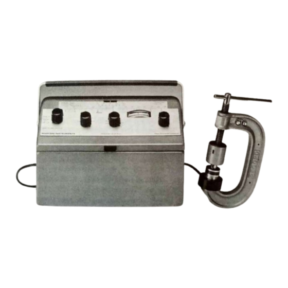
GENERAL INFORMATION Fig. 1.2 The moisture meter showing accessories Accessories available Standard Calibration Data: TM 4473A/1 Cereal grains and agricultural seeds Flour and wheat TM 4473A/2 Cigarette tobacco TM 4473A/3 Tick beans TM 4473A/8 Polished rice and paddy TM 4473A/9 Paper TM 4473A/10 Special Calibration Data;... -
Page 8: Chapter 2 Operation
Chapter 2 OPERATION 2.1 Installation lhe performance of this instrument may be impaired by lengthy exposure to a NOTE: damp atmosphere. Drying for a short period in a warm dry atmosphere will restore it give normal performance. Ensure that the instrument is switched OFF before connecting any leads and only switched on when actually taking measurements, hence prolonging the life of the batteries. -
Page 9: Calculator Scales
OPERATION Calculator scales tested slide the scale into position see Fig. If a scale is available for the substance to be calibration data sheet. 1.1. If there is no scale available then select the appropriate following sections give the general method of operating the instrument. Detailed calibration data supplied for each procedures that apply to particular materials are given in the group of substances. - Page 10 OPERATION Unscrew the clamp. Withdraw the test cell. Take out the plunger. See that the insulating ring is well seated on the electrode with its open end upwards. In Do not handle the upper surface as this may deposit handling the electrode, hold by the edges. moisture on the insulating surface between the two electrode rings.
-
Page 11: Sheets And Boards (E.g. Cardboard)
OPERATION Sheets and boards (e.g. cardboard) materials. Thin sheets cell are not required for these The ring and plunger of the test inch. of about should be folded to give a thickness Fig. 2.2 Use of compression cell with thin sheet material Place the electrode in position on the base of the clamp. -
Page 12: Reading The Instrument
OPERATION 2.5 READING THE INSTRUMENT Set Scale Slide the calculator between the central retaining clip and the BALANCE scale graduations as shown in Fig. 1.1. Move the scale along until the vertical index line on the central retaining clip is in alignment with the ambient temperature on the temperature scale. -
Page 13: Conven To Moisture Content
OPERATION Convert to moisture content Sliding scales fixed black scale. Transpose the readings obtained on the knob dials to the the point obtained on Read the actual moisture content on the sliding red scale opposite the fixed black scale. Paper charts If no scale is available for the substance under test, convert the dial reading to moisture content by means of the calibration data sheet. -
Page 14: Correcting For Sample Temperature
OPERATION should be taken. If these differ, one or two more should be taken. At least two readings accuracy, two readings ate usually sufficient if they differ by not more than For work of ordinary up to 40, one unit for readings between 40 and 50 and half a unit from 50 two units for readings 60 the equivalent moisture content scale contracts rapidly and readings to 55. -
Page 15: Chapter 3 Technical Description
Chapter 3 TECHNICAL DESCRIPTION 3.1 CIRCUIT DESCRIPTION The electrical measuring circuit, as shown in Fig. 7.1, consists of a Wheatstone bridge in which the specimen forms one arm and the two calibrated moisture controls form the ratio arms. The out-of-balance voltage is applied to the inputs of a FET differential amplifier and displayed on a centre zero meter. -
Page 16: Chapter 4 Maintenance
Chapter 4 MAINTENANCE 4.1 INTRODUCTION This chapter contains information for keeping the equipment in good working order and of trouble or for advice on servicing this instrument, checking the overall performance. In case please write or telephone your nearest representative, whose name and address can be found on of the instrument. -
Page 17: Cleaning
MAINTENANCE is important to remember the In connection with leakage across the electrode face it following rule: should be at least 10 The instrument rading on the empty test cell (without plunger) with the sample in position. divisions below, or preferably 15 to 20 below, the reading obtained O but for normal use a reading For testing very dry samples the 'empty' reading should be below wasting time on unnecessary... -
Page 18: Changing The Batteries
MAINTENANCE 9V CELLS REAR CASE cov€q CALIBRATION SOCKEIS RELEASE C HAN/ ELECTRODE SOCKETS STOWAGE CO*PRESSION CELL ASSEMB'V Access and layout Fig. 4.1 Access and layout 4.6 CHANGING THE BATTERIES A battery compartment accessible from outside the instrument has been fitted. two drawers Lift the and pull out to replace... -
Page 19: Chapter 6 Replaceable Parts
Chapter 6 REPLACEABLE PARTS Introduction This chapter lists replaceable parts in alphabetical order of their circuit references. following abbreviations and symbols are used: battery switch capacitor SKT: socket Carb: carbon transistor diode Var: variable meter wirewound Met: metal value selected during test; oxide normal value listed watts at 70 0 C... -
Page 20: Circuit
REPLACEABLE PARTS Ml Code Circuit Description reference Met film 1.1 kQ 2% aw 24773-274 Met film 10 kQ 2% -aw 24773-297 Carb 10 MO 24321-885 Met film 15 2% -aw 24773-301 Met film 10 kQ 2% -aw 24773-297 RI 1 Met film 1.5 2% -4W 24773-277... - Page 21 Chapter 7 CIRCUIT DIAGRAMS Circuit notes COMPONENT VALUES Resistors: no suffix = ohms, k = kilohms, M = megohms. Capacitors: no suffix = microfarads, p = picofarads. + = value selected during test, nominal value shown. SYMBOLS arrow indicates clockwise rotation of knob. etc., external front or rear panel marking.
- Page 22 CIRCUIT DIAGRAMS ELECTROOE CHEC SATO R16 0 STANDARDIZE 300k sxrc 3309 100M TENS AL ANCE UNITS DIAL 100k ALANC FUNCTION SELECTOR Fig. 7.1 Circuit diagram of moisture meter 46882-171 D Apr. 92...
- Page 23 Service Division Marconi Instruments Limited The Airport Luton Bedfordshire LU2 9NS Tel: (0582) 33866 Telex: 825248 Fax: (0582) 417573...
Need help?
Do you have a question about the 933D and is the answer not in the manual?
Questions and answers