Sign In
Upload
Download
Table of Contents
Contents
Add to my manuals
Delete from my manuals
Share
URL of this page:
HTML Link:
Bookmark this page
Add
Manual will be automatically added to "My Manuals"
Print this page
×
Bookmark added
×
Added to my manuals
Manuals
Brands
Oasis Manuals
Water System
Modular Series
User manual
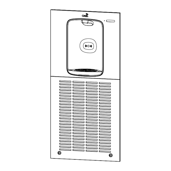
Oasis Modular Series User Manual
Electronic bottle fillers
Hide thumbs
Also See for Modular Series
:
User manual
(23 pages)
1
2
3
4
5
6
7
8
9
10
11
12
13
14
15
16
17
18
Table Of Contents
19
page
of
19
Go
/
19
Contents
Table of Contents
Bookmarks
Table of Contents
Section 1: Bottle Filler Assembly with Chiller Overview
Section 2: Installation
Section 3: Mw8Ebf, Mw12Ebf (Connecting the Chiller)
Section 4: M8Ebf/M12Ebf Chiller and Fountain Connections
Section 5: Trim Bezel Installation (for Surface Mount Models)
Section 6: Panel Installation
Section 7: Set-Up Guide for Bottle Filler Electronics
Section 8: Parts Breakdown
Advertisement
Quick Links
1
Section 7: Set-Up Guide for Bottle Filler Electronics
Download this manual
User Guide
Modular Series
Electronic Bottle Fillers:
MWEBF, MW8EBF, MW12EBF,
MWSMEBF, MWSM8EBF and
MWSM12EBF, MEBF, M8EBF,
M12EBF, MEBFEE, M8EBFEE,
M12EBFEE
Please read these instructions before installing this product
Table of
Contents
Previous
Page
Next
Page
1
2
3
4
5
Advertisement
Table of Contents
Need help?
Do you have a question about the Modular Series and is the answer not in the manual?
Ask a question
Questions and answers
Subscribe to Our Youtube Channel
Related Manuals for Oasis Modular Series
Water System Oasis MWEBQ User Manual
Electronic bottle fillers (23 pages)
Water System Oasis MWEBF User Manual
Electronic bottle fillers (19 pages)
Water System Oasis MWSM8EBF User Manual
Electronic bottle fillers (19 pages)
Water System Oasis M8EBF User Manual
Electronic bottle fillers (19 pages)
This manual is also suitable for:
Mwebf
Mw8ebf
Mw12ebf
Mwssmebf
Mwsm8ebf
Mwsm12ebf
...
Show all
Mebf
M8ebf
M12ebf
Mebfee
M8ebfee
M12ebfee
Table of Contents
Print
Rename the bookmark
Delete bookmark?
Delete from my manuals?
Login
Sign In
OR
Sign in with Facebook
Sign in with Google
Upload manual
Upload from disk
Upload from URL


Need help?
Do you have a question about the Modular Series and is the answer not in the manual?
Questions and answers