
Related Manuals for Gravely Pro-Walk Gear 32GR


Summary of Contents for Gravely Pro-Walk Gear 32GR
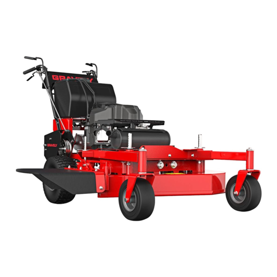
- Page 1 Pro-Walk Gear Operator’s Manual Manuel de I’utilisateur Models 988150 – 32GR (SN 030000 +) 988151 – 36GR (SN 030000 +) 988152 – 48GR (SN 030000 +) ENGLISH • 04263400B 3/18 FRANÇAIS Printed in USA...
-
Page 2: Table Of Contents
TABLE OF CONTENTS WELCOME ..... . 1 MAINTENANCE ....18 Service Position . -
Page 3: Welcome
WELCOME Congratulations on your purchase and welcome to the Gravely family! Every machine in the Gravely lineup is designed for long-lasting and unsurpassed performance. We are confident your machine will be part of your family for many years to come. -
Page 4: Safety
Failure to follow these instructions and warnings may cause death 2. Warning or serious injury. If you have purchased this product from a Gravely dealer, the dealer can WARNING: Indicates a provide you with training. POTENTIALLY HAZARDOUS Familiarize yourself and any other operators... -
Page 5: Safety Decals Locations
4. Notice SAFETY DECALS LOCATIONS NOTICE: Indicates information or procedures The safety decals on your machine are visual that are considered important but not hazard reminders of the important safety information related. If not followed, property damage found in this manual. All messages found on could result. - Page 6 1. DANGER! 3. WARNING! Discharge Hazard – NEVER direct discharge toward AVOID INJURY. Stay clear people, pets or property. of rotating parts. Thrown objects can cause injury or damage. Amputation Hazard – NEVER stick hands or feet Keep hands away from all under deck or shielded rotating or moving parts.
-
Page 7: Safety Rules
SAFETY RULES Discharge Hazard - NEVER The following safety instructions are based direct discharge toward on the B71.4 specifications of the American people, pets or property. National Standards Institute and ISO 5395 in Thrown objects can cause effect at the time of production. injury or damage. - Page 8 Data indicates operators age 60 years and Inspect the area where the equipment is to above are involved in a large percentage of be used and remove all objects such as mower-related injuries. rocks, toys and wire which can be thrown by the machine.
- Page 9 This product is equipped with an internal Stop on level ground, lower implements, combustion-type engine. DO NOT use unit disengage drives, engage parking brake (if on or near any unimproved, forest-covered provided), disengage PTO, shut off engine or brush-covered land unless exhaust and allow moving parts to stop before system is equipped with a spark arrester leaving the operator’s position for any...
- Page 10 Check for weak spots on docks, ramps or Operation on slopes may lead to loss of floors. Avoid uneven work areas and rough steering control. When operating on slopes terrain. Stay alert for hidden hazards or be prepared to react to an emergency traffic.
- Page 11 Fuel is highly flammable and its vapors are Batteries explosive. Handle with care. Use only an Avoid Electric Shock. Objects contacting approved gasoline container with an both battery terminals at the same time may appropriately sized dispensing spout. result in injury and unit damage. DO NOT NO smoking, NO sparks, NO flames.
- Page 12 ALWAYS block wheels and know all jack Storage stands are strong and secure and will hold NEVER store unit with fuel in fuel tank inside weight of unit during maintenance. Use jack a building where any ignition sources are stands to support components when present.
-
Page 13: Controls & Features
CONTROLS & FEATURES Figure 3 1. Ignition Switch 11. Height-of-Cut Adjustment System 2. Choke Control Knob 12. Discharge Chute 3. Throttle Control Lever 13. Hour Meter 14. Oil Fill / Dipstick 4. PTO Switch 15. Oil Drain 5. Operator Presence Controls 16. -
Page 14: Ignition Switch
THROTTLE CONTROL LEVER WARNING: AVOID INJURY. See Figure 6. Read and understand the Safety Controls engine speed. section before proceeding. Fast See Figure 3 for all controls and features locations. IGNITION SWITCH See Figure 4. Controls power to the engine. The key cannot be removed when in the on position. -
Page 15: Operator Presence Controls
OPERATOR PRESENCE SHIFT LEVER CONTROLS See Figure 10. See Figure 8. Sets the direction and speed of the unit. Operator presence control levers must be engaged to operate traction drive or PTO. When the shift lever or PTO is engaged, releasing the operator presence controls stops the engine. -
Page 16: Before Operation
6. Adjust steering levers. See Adjust Steering Levers on page 21. 7. Check function of the Safety Interlock System by performing the tests below. Contact your Gravely dealer for repair if any of the tests fail. TEST SAFETY INTERLOCK Figure 11... -
Page 17: Additional Cutting Height
See Figure 13 for HOC rod positions. HOC Rod Position (Front Shown) HOC Rod Position (Rear Shown) 1. HOC Rod 2. Washer 3. Spacer HOC Rod Cut Height Washer 4. Hair Pin Hair Pin Inch (mm) 5. Hex Bolt Position Figure 12 1.5 (38) 1.75 (44) -
Page 18: Operation
OPERATION WARNING: AVOID INJURY. Read and understand the Safety section before proceeding. IMPORTANT: All references to left, right, front or rear are given from the perspective of operator in operator’s position, facing the direction of forward travel. 1. Blade EMERGENCY STOPPING 2. -
Page 19: Stop The Engine
2. You can move the shift lever one of two Operate Unit in Reverse ways: 1. Hold the steering levers against the a. Continue to hold steering levers handlebar. against handlebar and use your knee 2. Engage steering lever latches. to move the shift lever to the desired 3. -
Page 20: Maintenance
Interlock System unit. The following chart shows the recommended service schedule. Check Engine Oil* • Your Gravely dealer can provide service and Change Engine Oil* adjustments to keep your unit operating at Check Tire Pressure • peak efficiency. Contact an authorized engine manufacturer’s service center for engine... -
Page 21: Hour / Maintenance Meter
3. Apply grease to the half shafts located LUBRICATE UNIT below the fuel tank. See Figure 19. Gravely recommends using Gravely Hi-Temp Grease or equivalent (see Service Parts on page 17) to lubricate fittings. Lubricate each season or every 25 hours of operation. -
Page 22: Check Mower Blades
CHECK MOWER BLADES DO NOT sharpen to Check blades for wear. Replace or sharpen this pattern. as needed. CAUTION: AVOID INJURY. Use sturdy gloves or padding to protect hands when working with mower blades. Rotation of one blade rotates the other blades. -
Page 23: Service And Adjustments
NOTICE: Ensure that hair pins are located in SERVICE AND the same holes at all deck mounting ADJUSTMENTS locations. Always store the hair pins on the height-of-cut pins. WARNING: Read and understand the Safety section before proceeding. ELECTRICAL SERVICE See Figure 23. IMPORTANT: To avoid damaging the circuit, replace fuses with fuses of the same amperage rating. -
Page 24: Adjust Brakes
ADJUST BRAKES See Figure 26. NOTICE: The traction belt must disengage as the brake starts to engage. 1. Stop engine, remove key and wait for all moving parts to stop and for hot parts to cool. 2. If brakes do not disengage fully when traction belt is engaged: •... -
Page 25: Replace Traction Belts
REPLACE TRACTION BELTS Remove Traction Belt 1. Stop engine, remove key and wait for all moving parts to stop and for hot parts to cool. 2. Release the steering levers. 3. Raise the rear of the unit so the drive wheels are off the ground. -
Page 26: Adjust Shift Lever Linkage
ADJUST SHIFT LEVER LINKAGE .8mm (.030") See Figure 29. IMPORTANT: If the shift lever and the transmission detent are improperly aligned, the transmission may fail prematurely. The .030 (.8mm) clearance helps prevent premature wear of the detent plate and shift lever. -
Page 27: Replace Mower Drive Belt
7. Remove transmission belt from clutch REPLACE MOWER DRIVE BELT sheave and transmission sheave. CAUTION: Damaged or worn Install Transmission Belt belts may result in injury and / or 1. Install transmission belt in the top groove damage to the unit. Check belts of the clutch hub and on the transmission for excessive wear or cracks sheave. - Page 28 Install Mower Drive Belt See Figure 33. 1. Install belt. 2. 32" and 36" Models Only: Tighten the adjusting nut until the idler spring extends to 34.3 cm ± .64 cm (13.5" ± 1/4"). 3. 48" Models Only: Tighten the adjusting nut until the idler spring extends to 35.5 cm ±...
-
Page 29: Storage
STORAGE ACCESSORIES See your Gravely dealer for a complete list of WARNING: Read and compatible accessories and attachments for understand the Safety section your unit. before proceeding. Description Part No. Needle Bearing Kit 21550331 SHORT-TERM STORAGE 32" Mulch Kit (988150) -
Page 30: Troubleshooting
Check safety interlock system. See engage or is faulty. Test Safety Interlock System on page 14. Electrical system is faulty. Contact your Gravely dealer. Engine is faulty. Contact your Gravely dealer. Choke control knob is in on Move knob to off position. - Page 31 TROUBLESHOOTING Problem Probable Cause Correction Mower blades are dull or faulty. Sharpen or replace mower blades. See Sharpen Blades on page 20. Mowing speed is too fast. Drive slower when cutting grass. Belt tension or condition is poor. Replace transmission belt or mower Unit has poor drive belt.
-
Page 32: Specifications
22 (5.8) Type Refer to Engine Manual Transmission Type Peerless 5-Speed + Reverse Use 15W-50 synthetic motor oil (Gravely p/n 00057100) or equivalent Drive Speed Forward Maximum – km/h (mph) 5.4 (8.7) Reverse Maximum – km/h (mph) Reverse Assist Turning Radius... -
Page 33: Warranty
Equipment Limited Warranty Warranty Ariens Company (Ariens) warrants to the original purchaser that Ariens, Gravely and Countax brand products purchased on or after 9/1/2017 and designated or labeled commercial products by Ariens Company will be free from defects in material and workmanship for the time period noted in the chart below. - Page 34 Exclusions – Items Not Covered by This Warranty • Parts that are not genuine Ariens, Gravely or Countax service parts are not covered by this warranty and may void the warranty. • Damages resulting from the installation or use of any part, accessory, or attachment which is not approved by the Ariens Company for use with product(s) identified herein are not covered by this warranty.
- Page 35 • Products are designed to the specifications in the area that the product was originally distributed. Different areas may have significantly different legal and design requirements. This warranty is limited to the requirements in the area in which the unit was originally distributed.
- Page 36 655 West Ryan Street Brillion, WI 54110 gravelymower.com gravely.custhelp.com...
Need help?
Do you have a question about the Pro-Walk Gear 32GR and is the answer not in the manual?
Questions and answers