Table of Contents
Advertisement
Quick Links
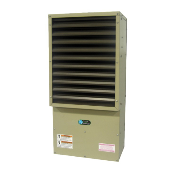
MiniPac™
Environmental Control Unit
Operation and Installation Manual
Models ECUA06ACAxxxA2, A3, & A5
ECUA06ACxxxA3
ECUA06ACxxxA5
Manufactured By:
Industrial Climate Engineering
Division of AIRXCEL
, Inc.
™
™
P.O. Box 5104 • Cordele, Georgia 31010-5104
2002 Hoover St. • Cordele, Georgia 31015
E-mail: ice@airxcel.com • Internet: www.acice.com
Part No. 01725 7/2014 new
Advertisement
Table of Contents
Troubleshooting

Summary of Contents for Industrial Climate Engineering MiniPac ECUA06ACA A2 Series
- Page 1 Environmental Control Unit Operation and Installation Manual Models ECUA06ACAxxxA2, A3, & A5 ECUA06ACxxxA3 ECUA06ACxxxA5 Manufactured By: Industrial Climate Engineering Division of AIRXCEL , Inc. ™ ™ P.O. Box 5104 • Cordele, Georgia 31010-5104 2002 Hoover St. • Cordele, Georgia 31015 E-mail: ice@airxcel.com •...
- Page 2 Failure to comply could result in minor personal injury and/or property damage. CAUTION IMPORTANT is used to point out helpful suggestions that will result in improved installation, reliability or operation. SPECIFICATIONS SUBJECT TO CHANGE WITHOUT NOTICE. © 7/2014 Industrial Climate Engineering Div. Airxcel , Inc. ™...
-
Page 3: Table Of Contents
WARNING • If the information in these instructions are not followed exactly, a fire may result causing property damage, personal injury or loss of life. • Read all instructions carefully prior to beginning the installation. Do not begin installation if you do not understand any of the instructions. •... -
Page 4: Chapter 1 Description & Specifications
Chapter 1 Description & Specifications General Description The ECUA06 Environmental Control Unit (ECU) is specifically designed to cool and heat electronic cabinets. It is designed to mount either on an exterior wall or door. The units are typically controlled by a thermostat placed inside the cabinet (an optional internal thermostat is available). - Page 5 to the liquid pressure conditions. The condenser blower always turns on after the compressor and will cycle frequently during normal operation at low temperatures. • Condenser motor powered directly through this switch. • Circuit closes (motor on) at ~400 psi and opens (motor off) at ~245 psi. •...
-
Page 6: Function/Description Of Major Control Board Components
Evaporator Blower and Motor (EBM) • Twin blower and motor. • Pulls cabinet air through evaporator and discharges cooled air back to cabinet. • Squirrel cage blower design. • Blower and motor combination must be replaced as complete unit. • Shaded pole motor. -
Page 7: Electronic Control Board Mode Of Operation
Evaporator Blower Motor Capacitor (N3 series only) • Start/run capacitor for PSC evaporator motor. • 3 µfd @ 440 VAC. • Provides starting torque and improves operating efficiency. • Built into the 115V motor, separate on 230V motor. Condenser Blower Motor Capacitor •... - Page 8 LED Indicator Lights COLOR TYPE STATUS DESCRIPTION Green Power Constant On 24 VAC power has been applied Status Constant On Normal operation Status 1 Blink High pressure switch has opened twice Status 2 Blinks Low pressure switch has opened twice Status 3 Blinks Frost sensor has opened twice...
-
Page 9: Installation
WARNING Failure to observe and follow Warnings and Cautions and these Instructions could result in death, bodily injury or property damage. Read this manual and follow its instructions and adhere to all Cautions and Warnings in the manual and on the ICE unit. Installation Equipment Inspection Inspect all cartons and packages upon receipt for damage in transit. -
Page 10: Start-Up And Check Out
3. If the unit is mounted outside, a small bead of silicone should be applied to the perimeter. Additionally, weather flashing should be installed over the top rear edge. 4. Place ECU on cabinet and attach to cabinet with high strength mounting screws. Use all holes to ensure stability and a tight seal. -
Page 11: Ratings, Wiring And Identification
Ratings, Wiring and Identification Summary Ratings ELECT. HEAT 000 = None 005 = 0.5 kW 010 = 1.0 kW 022 = 2.2 kW 036 = 3.6 kW BASIC VOLTAGE CKT #1 CKT #1 CKT #1 CKT #1 CKT #1 MODEL PHASE / HZ ECUA06ACA (A) 208-230/1/60... - Page 12 Figure 2. MiniPac™ ECUA06 A2 & A3 Series Schematic ECUA06 7/2014 new...
- Page 13 FRONT LEFT SIDE BACK Figure 3a. MiniPac™ ECUA06 A2 Series Dimensional Data Figure 3b. MiniPac™ ECUA06 A3 Series Dimensional Data ECUA06 7/2014 new...
- Page 14 SUPPORT POINTS SUPPORT POINTS Figure 3c. MiniPac™ ECUA06 A5 Series Dimensional Data ECUA06 7/2014 new...
-
Page 15: Internal Thermostat Operating Instructions
1.10 Internal Thermostat Operating Instructions ECUA06 7/2014 new... - Page 16 ECUA06 7/2014 new...
- Page 17 ECUA06 7/2014 new...
- Page 18 ECUA06 7/2014 new...
- Page 19 ECUA06 7/2014 new...
- Page 20 ECUA06 7/2014 new...
-
Page 21: Chapter 2 Troubleshooting
Chapter 2 Troubleshooting Overview A comprehensive understanding of the operation of the ECUA06 is a prerequisite to troubleshooting. Industrial Climate Engineering 's MiniPac™ ECUs are thoroughly tested before they are shipped ™ from the factory. Of course, it is possible that a defect may escape undetected, or damage may have occurred during transportation. - Page 22 PROBLEM/SYMPTOM LIKELY CAUSE(S) CORRECTION B. Unit runs for long periods or continu- 1. Dirty filter or reduced airflow 1. Check air filter(s). Check blower operation. Remove ously; cooling is insufficient. airflow restriction. 2. Loss of refrigerant. 2. Check for proper charge and possible refrigerant leak. 3.
-
Page 23: Compressor Troubleshooting
Compressor Troubleshooting NOTE: It is important to rule out other component failures before condemning the compressor. The following electrical tests will aid diagnosis: 1. Start-Up Voltage: Measure the voltage at the compressor terminals during start-up. The voltage must exceed the minimum shown in chart below, or compressor failure is likely. A low voltage condition must be corrected. -
Page 24: Chapter 3 Maintenance
Chapter 3 Maintenance Scheduled Maintenance Following is a list of maintenance items which should be performed on a regular basis. These instruc- tions supersede any previous maintenance instructions given in earlier bulletins. To be performed a minimum of twice a year: •... -
Page 25: Chapter 4 Warranty
Chapter 4 Warranty Limited Product Warranty If any part of your Industrial Climate Engineering™ Environmental Control Unit (ECU) fails because of a manufacturing defect within fifteen months from the date of original shipment by ICE or within twelve months from the date of original start-up, whichever is the earlier date, ICE will furnish without charge, EXW Cordele, Georgia, the required replacement part.
Need help?
Do you have a question about the MiniPac ECUA06ACA A2 Series and is the answer not in the manual?
Questions and answers