Sign In
Upload
Download
Table of Contents
Contents
Add to my manuals
Delete from my manuals
Share
URL of this page:
HTML Link:
Bookmark this page
Add
Manual will be automatically added to "My Manuals"
Print this page
×
Bookmark added
×
Added to my manuals
Manuals
Brands
Pottinger Manuals
Farm Equipment
NOVADISC 222
Operator's manual
Pottinger NOVADISC 222 Operator's Manual
Disc mower
Hide thumbs
1
2
3
Table Of Contents
4
5
6
7
8
9
10
11
12
13
14
15
16
17
18
19
20
21
22
23
24
25
26
27
28
29
30
31
32
33
34
35
36
37
38
39
40
41
42
43
44
45
46
47
48
49
50
51
52
53
54
55
56
57
58
page
of
58
Go
/
58
Contents
Table of Contents
Bookmarks
Table of Contents
Table of Contents
Symbols USED
CE Mark
Safety Hints
Introduction
Meaning of the Transfers
Transfer Position
TRACTOR Requirements
Tractor
Ballast Weights
Lifting Unit (Three-Point Linkage)
Hydraulic Control on the Lifting Gear
Necessary Hydraulic Connections
Power Connections Required
Safety Advice
Hitching Implement to Tractor
General Tips
Parking in the Working Position
Parking in Transport Position (Optional)
Unhitching Implement from Tractor
Parking in the Open
Transport Position
General Safety Information
Transport Position (T)
Starting Situation
Switching to Transport Position
Road Transport
Lighting for Road Travel
Working POSITION
General Safety Information
Initial Situation for Lowering the Cutter Bar
Change to Working Position
Working on Slopes
Safety Advice
Starting Work
Turning When Mowing
Mowing
Reversing
General Guidelines on Working with the Machine
Collision Avoidance
Straw Divider
Safety Advice
Wear and High Cut Skids
Swath Former
Additional Swath Former
Protective Apron
Conveying Cones (Optional)
General Maintenance
Safety Advice
General Maintenance Information
Cleaning of Machine Parts
Parking in the Open
Winter Storage
Articulated Shafts
Hydraulic Unit
General Safety Information
Oil Level Check, Angular Gear
Angular Gear Oil Change
Cutter Bar Oil Level Check
Cutter Bar Oil Change
Setting the Pre Load of the Folding Aid
Installing Cutter Blades
Factory Setting of the Relief Springs
V-Belt Drive
Hydraulic Plan
Wear Control Cutting Blades Bracket
Holder for the Rapid Change of Mowing Blades
Mowing Blades Suspension Checks
Changing the Cutting Blades (from Year of Construction 2004)
Storing of the Lever
Technical DATA
The Designated Use of the Mower Unit
Optional Equipment
Necessary Connections
Type Plate Position
Supplement
Safety ADVICE
Lubrication Chart
Novacat 222
Novacat 262
Novacat 302
Novacat 352
Lubricants
Supplement
Mounting Options
Taper Bushes Installation Instructions
Combination of Tractor and Mounted Implement
Advertisement
Quick Links
1
Oil Level Check, Angular Gear
2
Cutter Bar Oil Change
3
Novacat 302
Download this manual
Operator's manual
Nr. 99+3741.EN.80V.0
Translation of the original Operating Manual
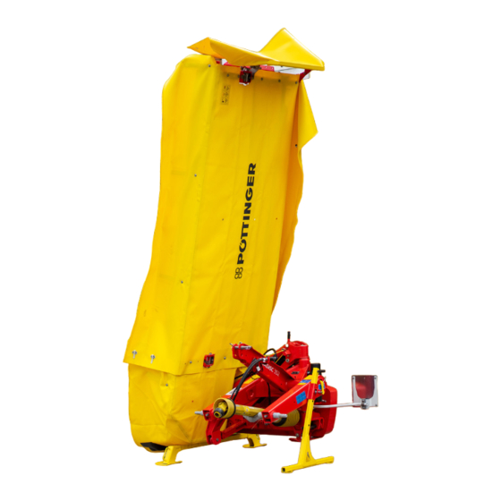
Disc mower
NOVADISC 222
(Type PSM 3741 : + . . 01001)
NOVADISC 262
(Type PSM 3742 : + . . 01001)
NOVADISC 302
(Type PSM 3743 : + . . 01001)
NOVADISC 352
(Type PSM 3744 : + . . 01001)
Table of
Contents
Previous
Page
Next
Page
1
2
3
4
5
Advertisement
Table of Contents
Need help?
Do you have a question about the NOVADISC 222 and is the answer not in the manual?
Ask a question
Questions and answers
Related Manuals for Pottinger NOVADISC 222
Farm Equipment Pottinger Euroboss 250 T Operator's Manual
(96 pages)
Farm Equipment Pottinger VITASEM 250 Mounting Instructions
(12 pages)
Farm Equipment Pottinger EUROCAT 272 Operator's Manual
(58 pages)
Farm Equipment Pottinger NOVACAT 261 Operator's Manual
Disc mower (63 pages)
Farm Equipment Pottinger EUROTOP 422 A Operator's Manual
Rotary swather (46 pages)
Farm Equipment Pottinger EUROCAT 271 classic Operator's Manual
(42 pages)
Farm Equipment Pottinger NOVADISC 262 Operator's Manual
Disc mower (58 pages)
Farm Equipment Pottinger NOVACAT 262 Operator's Manual
Disc mower (70 pages)
Farm Equipment Pottinger NOVADISC 732 Operator's Manual
Disc mower (58 pages)
Farm Equipment Pottinger NOVADISC 902 Operator's Manual
Disc mower (58 pages)
Farm Equipment Pottinger NOVADISC 302 Operator's Manual
Disc mower (58 pages)
Farm Equipment Pottinger NOVADISC 352 Operator's Manual
Disc mower (58 pages)
Farm Equipment Pottinger HIT 470 N Operator's Manual
Tedder (30 pages)
Farm Equipment Pottinger EUROTOP 601 A Operator's Manual
Double rotary swather (35 pages)
Farm Equipment Pottinger ROLLPROFI 6165 Operator's Manual
(216 pages)
Farm Equipment Pottinger EUROTOP 771 A Operator's Manual
(33 pages)
This manual is also suitable for:
Novadisc 262
Novadisc 302
Novadisc 352
3741
3742
3743
...
Show all
3744
Table of Contents
Print
Rename the bookmark
Delete bookmark?
Delete from my manuals?
Login
Sign In
OR
Sign in with Facebook
Sign in with Google
Upload manual
Upload from disk
Upload from URL


Need help?
Do you have a question about the NOVADISC 222 and is the answer not in the manual?
Questions and answers