
Related Manuals for Frye FONIX COLT


Summary of Contents for Frye FONIX COLT
- Page 1 FONIX® COLT™ MAINTENANCE MANUAL April 23, 2013 Copyright ©2013 Frye Electronics, Inc. All Rights Reserved...
-
Page 3: Table Of Contents
Table of Contents Chapter 1: Overview . . . . . . . . . . . . . . . . . . . . . . . . . . . . . . . . . . . . . . . . . . . . . . . . . . . . . . . . . . . .1 1.0 Power on procedure for the Colt Audiometer . - Page 4 4.8. Power Regulators ..............19 4.9.
-
Page 5: Chapter 1: Overview
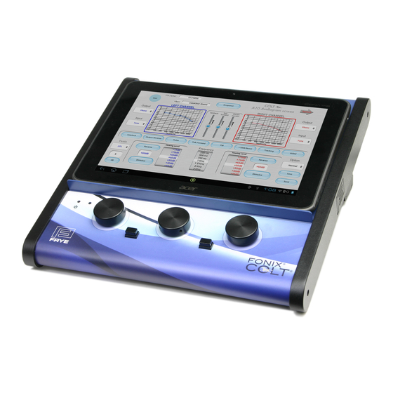
Chapter 1: Overview 1.0 Power on procedure for the Colt Audiometer The basic Colt audiometer consists of two parts, the tablet and the main Colt base unit. Both have to be powered and Blue Tooth wireless communication between the two has to be established before operation. The procedure to follow: Step 1- Turn on the power to the base colt unit To turn on the power, plug the Colt line cord into a suitable source of AC power... - Page 6 Touch the lock and slide it to the right. The home screen will then appear. Step 3- Select the Colt icon from the home screen Touch the FRYE/Colt logo icon on the screen to launch the Colt application. Maintenance Manual...
-
Page 7: A Description Of The Colt Audiometer System
The pure tone Colt app screen will appear. A message will be seen on the screen, indicating that blue tooth service is being actuated. When the start-up sequence is complete, the tone from the monitor headset will stop, indicating that communication and control has been established by the tablet. Test the control by pressing the Stimulus button on either the right or left channel. -
Page 8: The Tablet Operator Interface
1.2 The Tablet Operator Interface But then, how is it different from any other audiometer? The differences and advan- tages of the Colt lie in its operator interface. Instead of being computer based, it is actually based on a multiple of computers. And one of these is devoted to handling the operator interface. -
Page 9: Audio Power
Please note: The speaker output is from a class D amplifier. You cannot short out the ring and sleeve of the stereo speaker connectors on the Colt audiometer. If you purchase cables and speakers directly from Frye, the proper connections are made for you. -
Page 10: Portability And Data Storage
1.8 Portability and Data Storage The instrument's small size and light weight makes it easily transported, so when used in the field, a series of tests can be saved into the tablet's memory and later downloaded to a computer at the office. Test data files are linked to the patient num- ber. -
Page 11: Chapter 2: Specifications
Chapter 2: Specifications 2.1 General Characteristics Size: 11.3 x 11.5 x 4.2 inches (28.7 x 29.2 x 10.7 cm) Weight: 3.8 pounds (1.7 kg) (not including tablet) Mains Voltage: 100-240 VAC, 50 to 60 Hz 2.2 Pure Tone Signals Frequency Range Air conduction, sound field: 125 –... -
Page 12: Attenuators
Intensity Range (Sound Field) Single speaker 125 Hz: -10 to 60 dBHL 250 Hz: -10 to 80 dBHL 500 – 6000 Hz: -10 to 100 dBHL 8000 Hz: -10 to 90 dBHL Speech: -10 to 80 dBHL 2.3 Attenuators Range: -10 to 110 dBHL (120 dBHL with +10 dB boost pressed) in 1, 2, or 5 dB steps. -
Page 13: Vu Meters
2.6 VU Meters Range: -20 to +3 dB VU Accuracy: ± 1 dB at 0 dB, ± 2 dB at -10 and -20 dB Stereo Monitor Output: with adjustable volume 2.7 Channel Outputs Speaker: 10 watts RMS typical into 8 ohm sound field speak- ers (optional) Earphones: TDH39P: 100 ohm or Eartone 3A 50 ohm... -
Page 15: Chapter 3: Specification Test Procedure
Chapter 3: Specification Test Procedure 3.1 Pure Tone Audiometric screen 3.1.1 Testing against a “normal” hearing threshold. It is possible (and, in fact, encouraged) that frequent tests be run by a hearing pro- fessional to ensure that the Colt audiometer is in calibration. However, while these checks are useful in finding major calibration problems, they are obviously not suffi- cient to assure that the Colt audiometer is finely calibrated. -
Page 17: Chapter 4: Circuit Description
Chapter 4: Circuit Description 4.1 Introduction The Colt audiometer is “a new breed of audiometer” . This is readily apparent in its look and design, both inside and out. For instance, there is no circuit description for the wireless tablet that is used as the operator interface. It is treated as a single component. -
Page 18: Block Diagram And Circuit Diagrams
4.2 Block Diagram and Circuit Diagrams A Block Diagram is shown in Figure 4.2. Individual circuit elements are noted in this diagram and are covered in more detail in the circuit diagrams listed on sheets 1 through 10 in Chapter 10. ... -
Page 19: Cpu And Associated Circuits
Sheet 6 analog 60 dB attenuators, External outputs for lower level transducers, which include drives for external amplifiers, headphones, insert earphones, bone vibrator, and circuits for driv- ing the speaker power amplifiers. Sheet 7 Analog input amplifiers, including external line inputs, talk-forward microphone and talkback microphone with its chip decoder Sheet 8... -
Page 20: Dsp Circuits
Cabinet LED's are powered through J4. J5 is reserved for a possible upgrade. The JTAG port J6 is used for program debugging. Additional large sound files can be located in the microSD part through the socket J7. An additional system upgrade is possible by use of the “daughter board” connector J18. The same is also true for the option board connector J2. -
Page 21: Analog Input Signals
different types of noise are generated in U26.It also is programmed to provide signal switching and amplitude modifications. This part contains a power regulator for operation at 2.5 volts DC. 4.5. Analog input signals The AD1939 CODEC receives analog signals from four different channels or sources. Right and Left line inputs These come through amplifiers U9 and U8, which attenuate line level inputs before generating differential analog drives to the A/D channel inputs of the CODEC U20. -
Page 22: Speaker Power Output Amplifiers
6 outputs right and left audiometer channels left and right monitor channels two CPU channels Analog output channels As also mentioned above, left (U25) and right (U16) channel ear phone amplifi- ers are used to develop enough power to drive the output transducers directly or though attenuators as described below. -
Page 23: Power Regulators
4.8. Power Regulators A number of power regulators are used in the Colt to provide isolation between channels and to reduce noise. Separate regulators are used for both + 12V and – 12V supplies used for the right and left channels. Two additional regulators are used for the + 8V and –... -
Page 25: Chapter 5: Calibration
Chapter 5: Calibration 5.0 General The calibration of the Colt audiometer requires the use of a personal computer operat- ing under a Microsoft Windows operating system (XP Pro or later). A special program called ColtCal.exe is used to allow adjustment of the internal random access and flash memory elements inside the Colt. - Page 26 ER3A insert earphones, B71 bone vibrator and speaker outputs for pure tone and narrow band noise. A table of actual dB SPL outputs are shown in Table 5.1 for each frequency and device. Speech outputs add 20 dB to the SPL value at 1 kHz. ...
-
Page 27: Transducer Initial Data Entry
5.2.2 Transducer Initial Data entry To get started, work on the left TDH39 earphone. Click on the panel above the “Left Phone” sub-title. The calibration info edit panel will be displayed for that transducer. Figure 5.2.2 Click on the “Default” button to get started, or manually fill in the fields of the entry data list. - Page 28 If the target SPL level is not seen by the acoustic meter system, then the operator in- creases or decreases the level of drive by clicking the appropriate buttons to make an adjustment to achieve the required level. The level can also be adjusted by the inser- tion of a number into the provided window to make different jumps in amplitude.
-
Page 29: Chapter 6: Service And Repair
Chapter 6: Service and Repair 6.0 General Notes The construction of the Colt audiometer is unique in that the operator interface is formed by a tablet with a touch screen rather than a traditional keyboard and monitor. The circuits in the tablet are not serviceable except by personnel expert in the repair of that type of tablet. -
Page 30: Main Board Fuse Replacement
Fuse: (T1AH) 1A, 250V Type T, IEC 60127-2 sheet 5 (Time Lag Type, Ceramic, 5mm x 20mm). (See Section 8 - Rear Panel Safety Markings.) 6.1.2 Main Board Fuse Replacement Turn off power to the Colt and remove the power cord. Remove the bottom panel. (see figures 6a, and 6b). -
Page 31: Colt Circuit Assembly Removal And Separation
6.2. Colt Circuit Assembly Removal and Separation Turn off power to the Colt and remove the power cord. Referring to Figures 6d, remove the 3 screws in the bottom side on the upper panel and the 2 screws close to ... - Page 32 black. Plug in the three wire cable so that the colors match the labels on the J4 con- nector: Green to green and red to red. The center wire is black. Plug in the two wire cable so that the red wire is closest to the label marked “blue.” Slide the assembly into place, taking care that all the cables are not pinched on as- sembly.
-
Page 33: Chapter 7: Maintenance
Chapter 7: Maintenance 7.1 Power For your safety, disconnect the Colt from main power while cleaning. 7.2 Cleaning Wipe the Colt with a slightly moist cloth. Use plain water or water with mild dish- washing detergent. Wipe away any detergent with a moist cloth, then dry the Colt. Never allow fluid to enter: •The Colt Enclosure •The Colt switched power entry module. -
Page 35: Chapter 8: Safety Information
Chapter 8: Safety Information 8.0 Rear Panel Layout 8.1 Rear Panel Safety Markings Symbol Meaning “For continued protection against fire and electrical shock, replace only with same type and rating fuse.” The fuse specifications indicated on the Colt Rear Panel are as follows: Marking: T1AH... -
Page 36: Safety Classification For Iec 60601-1
CE signifies compliance with the European union’s Medical Devices Directive. 8.2 Safety Classification for IEC 60601-1 Type of protection against electric shock: Class 1 Degree of protection against electric shock: Type B Protection against harmful ingress of water: IPX0 Mode of operation: Continuous The Colt audiometer does not require sterilization or disinfection. -
Page 37: Chapter 9: Electromagnetic Compatibility
Chapter 9: Electromagnetic Compatibility 9.1 The Colt complies with IEC 60601-1-2. The Colt generates and uses radio frequency energy. In some cases the Colt could cause interference to radio or television reception. You can determine if the Colt is the source of such interference by turning the unit off and on. -
Page 38: Accessories With Which The Colt Complies With Iec 60601-1-2
Left speaker Right speaker 1.8 m 9.3 Accessories with which the Colt complies with IEC 60601-1-2 Peripheral Manufacturer Model Talk back microphone Frye Electronics, Inc. M828 Boom Mic. Headset Cyber Acoustics AC-202B (modified) Left insert earphone EAR Tone Right insert earphone... - Page 39 The Colt is intended for use in the electromagnetic environment specified below. The customer or the user of the Colt should assure that it is used in such an environment. Immunity test IEC 60601 Compliance level Electromagnetic environ- test level ment—guidance Electrostatic +/- 6 kV contact...
- Page 40 The Colt is intended for use in the electromagnetic environment specified below. The custom- er or the user of the Colt should assure that it is used in such an environment. Immunity test IEC 60601 test level Compliance Electromagnetic environment level —guidance Portable and mobile RF communica-...
-
Page 41: Recommended Separation Distances Between Portable And Mobile Rf Communications
9.5 Recommended separation distances between portable and mobile RF communications equipment and the Colt The Colt is intended for use in an electromagnetic environment in which radiated RF dis- turbances are controlled. The customer or the user of the Colt can help prevent electromag- netic interference by maintaining a minimum distance between portable and mobile RF communications equipment (transmitters) and the Colt as recommended below, according to the maximum output power of the communications equipment. -
Page 43: Appendix A: Connectivity Chart
Appendix A: Connectivity Chart Rear Panel Socket Connector PIN 1 (Tip) PIN 2 (Ring) PIN 3 (Sleeve) Talkback SIGNAL MIC ID GROUND Microphone External Input LEFT RIGHT GROUND Talk Forward SIGNAL GROUND PIN 1 PIN 2 PIN 3 Microphone 3.5mm Stereo (Required) Monitor LEFT RIGHT... - Page 44 Rear Panel Socket Connector PIN 1 (Tip) PIN 2 (Ring) PIN 3 (Sleeve) EARTH Mains Power LINE NEUTRAL GROUND IEC C13 PIN 1 PIN 2 PIN 3 PIN 4 SHELL DIGITAL CHASSIS VBUS GROUND GROUND Type B Maintenance Manual...
Need help?
Do you have a question about the FONIX COLT and is the answer not in the manual?
Questions and answers