
Related Manuals for Frye FONIX Hearing Evaluator FA-10


Summary of Contents for Frye FONIX Hearing Evaluator FA-10
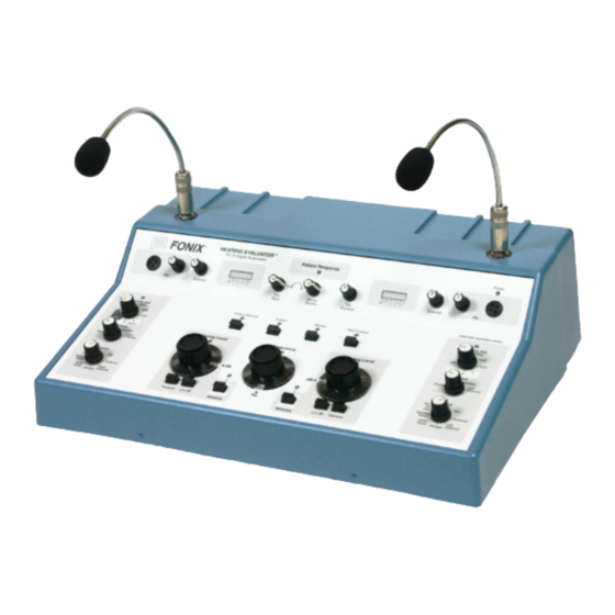
- Page 1 FONIX FA-10 ® Hearing Evaluator ™ Digital Audiometer Operator’s Manual version 1.22 © 2010, Frye Electronics, Inc. All Rights Reserved 6/09 Revised 06/18/10...
- Page 3 Note on this Manual We have organized this manual on the assumption that the user is already trained in how to do hearing tests. However, should that not be the case, or if the operator needs some help, Chapter Six, "Hearing Tests," may be consulted. Section 4.5 describes special tests that can be performed on the FA-10.
-
Page 5: Table Of Contents
Table of Contents Chapter 1: Introduction . . . . . . . . . . . . . . . . . . . . . . . . . . . . . . . . . . . . . . . . .1 1.1 Description . - Page 6 4.6 RS232 Option ........... . . 28 4.7 Dual Calibration Option.
-
Page 7: Chapter 1: Introduction
LEDs on the front panel. 1 .4 Service Contact Frye Electronics, Inc., P.O. Box 22391, Tigard, Oregon 97281 -3391, U.S.A. Shipments to 9826 SW Tigard St., Tigard, Oregon 97223. Telephone: 800/547-8209 in U.S. and Canada; 503/620-2722; Fax 503/639-0128; e-mail: ser- vice@frye.com. -
Page 8: Safety
“Read the accompanying documents.” Please read this manual before operating the FA-10. A separate maintenance manual also exists. If you wish to obtain one, please contact Frye Electronics or your Frye repre- sentative. For purposes of safety classification under IEC 60601-1, the FA-10 is class 1, type B, ordinary equipment suitable for continuous operation. - Page 9 If you are experiencing interference caused by the FA-10, you may be able to correct it by one or more of the following measures: Relocate or reorient the receiving antenna. Increase the distance between the FA-10 and the receiver. Connect the FA-10 to a different outlet than the receiver. Frye Electronics FONIX FA-10 Hearing Evaluator...
-
Page 10: Cleaning The Fa-10
Manor Royal Crawley West Sussex RH109TT ENGLAND Otherwise, please report all safety-related concerns to: Frye Electronics, Inc PO Box 23391 Tigard, OR 97281-3391 1 .6 Cleaning the FA-10 For your safety, disconnect the FA-10 from electrical power while cleaning. Wipe the FA-10 case with a slightly moist cloth. Use plain water or water with mild dish- washing detergent. -
Page 11: Standard Accessories
1 .7 Standard Accessories Telephonics Earphone Headband Patient Earphone, Telephonics TDH 39P 100 ohm (2 ea.) Telephonics Cushion (2 ea) Headphone Cord Operator’s Manual Bone Vibrator, Radioear B-71, 100 ohm Radioear Vibrator Headband Vibrator Cord Recording Pad Frye Electronics FONIX FA-10 Hearing Evaluator... -
Page 12: Optional Accessories
1 .8 Optional Accessories Dust cover Carrying case Monitor headset Talkback microphone Microphone stand Microphone stand, telescopic Gooseneck microphones (2 required) Boom microphone & headset Microphone, economy model Chapter 1: Introduction... - Page 13 Sound field speaker package Wall mount for speaker (pair) Insert earphone package, 3A/50 ohm Audio cups Headphone headband, pediatric Patient response switch CD player (includes mounting Adapter, Y-cable kit, Y cable) Gooseneck microphones not included Frye Electronics FONIX FA-10 Hearing Evaluator...
-
Page 15: Chapter 2: Specifications
50 ohms 250 Hz -10 to 90 dB HTL 500 Hz to 4 kHz -10 to 110 dB HTL 6 kHz -10 to 100 dB HTL 8 kHz -10 to 80 dB HTL Formerly ER3A Frye Electronics FONIX FA-10 Hearing Evaluator... - Page 16 BONE (ANSI-96): 250 Hz -10 to 40 dB HTL (Radioear B-71) 500 Hz to 750 Hz -10 to 60 dB HTL 100 ohms 1 kHz to 3 kHz -10 to 70 dB HTL 4 kHz -10 to 60 dB HTL 6 kHz -10 to 40 dB HTL 8 kHz...
- Page 17 LED bar graph type. One per channel. 1 dB resolution around 0 dB. Range from -20 to +3 dB VU. ACCURACY: +/- 1 dB at 0 dB +/- 2 dB at -10 & -20 dB. Frye Electronics FONIX FA-10 Hearing Evaluator...
- Page 18 For live voice tests this meter has the same characteristics described in American National Standard Volume Measurements of Electrical Speech and Program Waves, C16.5-1954 —(R1971) specifications for a VU meter, Sections 3.2 to 3.5 inclusive. Channel Outputs: Speaker: Three watts RMS typical into 8 ohm optional sound field speakers.
- Page 19 -10 dB +/- 1 dB ref 8 kHz 725 Hz -20 dB +/- 1 dB ref 8 kHz 18 db 4300 Hz -3 dB +/- 1 dB ref 8 kHz 1200 Hz -20 dB +/-1 dB ref 8 kHz *not guaranteed Frye Electronics FONIX FA-10 Hearing Evaluator...
-
Page 21: Chapter 3: Setting Up The Audiometer
Stereo Monitor Phones. (see detailed instructions included with this accessory) TURN ON THE POWER SWITCH ON THE REAR PANEL. The green indicator light on the upper right hand side of the audiometer will go on. Frye Electronics FONIX FA-10 Hearing Evaluator... -
Page 22: Rear Panel "See Manual" Symbols
MICROPHONE Figure 3.2 B The microphone inputs in figure 3.2 B are intended for use with the Frye electret condenser microphones, an optional accessory. Power for each microphone is provided over the signal line. If you substitute a non-electret microphone, the output of the microphone may be insuf- ficient. -
Page 23: Chapter 4: Operation
The right channel will go to the subject’s right ear; the left channel will go to the subject’s left ear (unless special steps are taken to change this condition). Frye Electronics FONIX FA-10 Hearing Evaluator... - Page 24 INPUT (Both Left and Right Channels) Left - blue earphone cable connector Right - red earphone cable connector The eight-position switches under “Input” on both sides of the Hearing Evaluator front panel are used to select the signal going to the chosen outputs. INPUT Selections are: Tone - When the marker is on Tone, pure tone is chosen (unless you have also pushed Warble, one of the toggle buttons found above the Frequency knob on the front panel).
-
Page 25: Output (Both Left And Right Channel)
(Note: when you use the Output Reverse button described in 4.3.4, it is not neces- sary to turn the channel on.) Warning Signals: When output levels for any condition are exceeded, or if the switch se- lection is incorrect, the red LED at Hearing Level will flash. Frye Electronics FONIX FA-10 Hearing Evaluator... -
Page 26: Presenting The Signal
4 .3 Presenting the Signal Frequency Hearing Level Hearing Level ✛ ✛ ▲ ✛ ✛ ✛ ✛ ✛ ✛ -2.5dB Reverse Reverse -2.5dB Stimulus Stimulus Figure 4.3: Controls for the Test Signal 4 .3 .1 Hearing Level Selection There are two amplitude or hearing level controls. The one on the operator’s right is ordinar- ily used to test the right ear, and the one on the operator’s left to test the left ear. -
Page 27: Reverse Button
0 +2 Figure 4.3.6: Digital VU Meter 4 .4 Miscellaneous Controls and Indicators Output Reverse Pulsed Warble Talk Forward Figure 4.4 A: Miscellaneous Controls and Indicators (Buttons located above the Hearing Level and Frequency knobs.) Frye Electronics FONIX FA-10 Hearing Evaluator... -
Page 28: Output Reverse
4 .4 .1 Output Reverse This button allows you to swap channels. The input of the right channel goes to the left chan- nel output. The input of the left channel goes to the right channel output. The LED above the button will indicate when this function is on. -
Page 29: External (Control)
•Set the right channel Hearing Aid Simulator switch to the desired test. Option A = ABLB Option B = MLB Option C = SISI Follow these steps: Frye Electronics FONIX FA-10 Hearing Evaluator... - Page 30 Option A: ABLB—Alternate Binaural Loudness Balance This is a test for binaural recruitment. Recruitment is an abnormally large increase in hearing sensation for a given increase in sound level. Derecruitment is an abnormally small increase in hearing sensation for a given increase in sound level. This test will automatically alternate a tone of a selectable frequency between the left ear and right ear.
- Page 31 (select desired reference frequency) (select test frequency) right stimulus Reverse: Frequency: (select desired test frequency) right Hearing Level: (select reference amplitude) left Hearing Level: (select test amplitude) Perform the desired right ear MLB hearing test. Frye Electronics FONIX FA-10 Hearing Evaluator...
- Page 32 Notes: Many other Option B setups are possible although the other Option B setups may not be de- fined as MLB. You may select different inputs and outputs. It is possible to alternate reference tone in one ear with test tone in the other ear. If Pulse is turned off, the frequency locking mechanism is still in effect.
- Page 33 30 dB = 3.0 dB increment 25 dB = 2.5 dB increment 20 dB = 2.0 dB increment 15 dB = 1.5 dB increment 10 dB = 1.0 dB increment 5 dB = 0.5 dB increment Frye Electronics FONIX FA-10 Hearing Evaluator...
-
Page 34: Rs232 Option
Information can be retrieved from the audiometer as either ASCII data streams or via the Frye Instrument Packet Protocol. The audiometer can be controlled via the Frye Instrument Packet Protocol only (for reliability reasons). All control positions on the audiometer front panel can be read at any time through the RS232 interface. -
Page 35: Dual Calibration Option
Hearing Aid Simulator knob. 4 .8 Connecting an iPod to the Audiometer You can purchase an iPod package for your FONIX Audiometer. Contents of the FONIX iPod Audiometric Package Frye Electronics FONIX FA-10 Hearing Evaluator... - Page 36 The FONIX iPod Audiometric package includes: • iPod nano loaded with the FONIX Audiometric Speech Tests • iPod dock • Dock power supply • USB Cable • Y-Cable Setup To set up the iPod for use with the FONIX audiometer: 1.
-
Page 37: Using The Fa-10 With A Cd Player Or Ipod
• one track (left or right) to one ear • one track (left or right) to both ears • both tracks (left and right) to one ear • both tracks (left and right) to both ears (1 track per ear) Frye Electronics FONIX FA-10 Hearing Evaluator... - Page 38 1 . One track to one ear A . To present the left track to the left ear only: Output Output Bone Speaker Bone Speaker Left Phone Phone Right Channel Channel Input Input Tone Narrow Tone Narrow Band Band Noise Noise Speech Speech...
- Page 39 3. Set right input knob to LEFT EXTERNAL. 4. Set right output knob to PHONE. 5. Press both right and left reverse buttons for continuous input from CD/iPod player. Both stimulus LED will light up. 6. Play track on CD/iPod player. Frye Electronics FONIX FA-10 Hearing Evaluator...
- Page 40 B . To present the right track to both ears: Output Output Bone Speaker Bone Speaker Left Phone Phone Right Channel Channel Input Input Tone Narrow Tone Narrow Band Band Noise Noise Speech Speech External External Noise Noise White Right White Left Noise...
- Page 41 6. Play track from CD/iPod player. To play the left track in the right ear and the right track in the left ear, use the setup above and press the Output Reverse button. Frye Electronics FONIX FA-10 Hearing Evaluator...
-
Page 43: Chapter 5: Using The Fa-10 To Help Select A Hearing Aid
With the Hearing Aid Simulator set to “Off,” obtain an estimate of the client’s Uncom- fortable Level (UCL) for speech. Add 15 dB to the obtained speech UCL to estimate the required SSPL 90. * (See notes on next page ) †/ Frye Electronics FONIX FA-10 Hearing Evaluator... - Page 44 Hearing Aid Simulator 12dB 18dB Figure 5.1 (Notes from previous page) When the audiogram slopes notably downward between 250 Hz and 1000 Hz, consider using the “ 6dB” setting. † This will cause the perceived loudness at “coarse MCL” to be closer to that obtained with the final slope setting. NOTE WELL: The “MCL”...
-
Page 45: Complete Instructions For Using The Hearing Aid Simulator
NOTE WELL: The “MCL” obtained with anything but a flat slope (“Off” setting) is not standard, and therefore should not be entered as “MCL” on an audiogram sheet without indicating the divergence from standard practice. Frye Electronics FONIX FA-10 Hearing Evaluator... - Page 46 Selecting Full-on Gain Tables 5.1 (p.33) and 5.2 (below) are guidelines for fitting monaurally to ears having average canal dimensions and normal middle-ear status. When fitting binaurally, slightly less gain may be required for MCL. Also, ITE and Canal instruments may require slightly less high- frequency gain.
- Page 47 Level of the test-ear-side only, until maximum clarity is achieved. This adjustment changes the level of the high frequencies, while maintaining a constant SPL for the lower frequencies, as Figure 5.2.1 on the next page illustrates. Frye Electronics FONIX FA-10 Hearing Evaluator...
-
Page 48: Selecting Maximum Output (Sspl 90)
Hearing Aid Simulator 12dB 18dB Figure 5.2.1 NOTE: The maximum HL with this setup is lower than it is when the two channels are not combined in this special manner. Do not use the “6dB”, “12dB”, or “18dB” settings with this setup . - Page 49 Table 5 .2 .2: To convert from dB HL to 2cc-coupler dB SPL, add these dB values to the measured dB HL values for each frequency measured .* FREQUENCY 1.5k * These measurements use the “Tone” setting of the audiometer Frye Electronics FONIX FA-10 Hearing Evaluator...
-
Page 51: Chapter 6: Hearing Tests With The Hearing Evaluator
If you can, find out which ear is likely to be the better one by asking the patient. 6 .2 The Speech Reception Threshold (SRT) Audiometer Settings Input: Mic (for live voice) or External (for recorded voice) Output: Phone Frye Electronics FONIX FA-10 Hearing Evaluator... - Page 52 Hearing Level: 70 dB (initial setting) Hearing Aid Simulator: Reverse (near “-2.5 dB” button): Adjust the Mic or External trim controls (on upper panel near VU meters) so that when you present the words, the VU meter indicates the “0” level. It is a good idea to start the hearing tests by finding the patient’s hearing sensitivity level for speech.
-
Page 53: Puretone Audiometry
Be sure the patient responds to each presentation. Important: Vary the time interval between each presentation, so the patient does not recognize a rhythmic pattern. * The puretone average is the average of the thresholds at 500, 1000 and 2000 Hz. Frye Electronics FONIX FA-10 Hearing Evaluator... -
Page 54: Bone-Conduction Tests
When the patient no longer responds to the tone, you know you have passed the hear- ing threshold level. Now increase the hearing level in 5-dB steps between presentations until the patient again responds. Remember this level, it is your first measure of thresh- old. - Page 55 Pressure is needed to help the bone vibrator stimulate skull vibrations. PINNA (Bone Vibrator should MASTOID BUMP not touch the Pinna) (Place Bone Vibrator here) Figure 6.3.2: For Bone Conduction Testing Frye Electronics FONIX FA-10 Hearing Evaluator...
- Page 56 Press the Reverse button under the Hearing Level control to activate the tone. With the vibrator in its original position on the mastoid, ask the patient if they hear the tone. When the patient responds, “Yes, I hear it,” tell the patient, “I want to find the best place to put the vibrator.
-
Page 57: Supra-Threshold (Above Threshold) Tests
The first selection is never recorded, as patients often change their mind after listening to various levels. Bracket the MCL by presenting levels a- little-higher-than MCL and a-little-less-than MCL. Repeat this procedure on the other ear and record your results. Frye Electronics FONIX FA-10 Hearing Evaluator... -
Page 58: The Uncomfortable Level (Ucl) For Speech
6 .4 .2 The Uncomfortable Level (UCL) for Speech The UCL is the level at which the patient says the sound is uncomfortably loud. Approach this test cautiously. Some patients do not like loud sounds and they can become angered quickly if they are exposed to a sudden loud sound. -
Page 59: Setting The Masking Levels For Thresholds
* The puretone average is the average of the thresholds at 500, 1000 and 2000. ** The “air-bone gap” is the difference between the air- and bone-conduction thresholds. Frye Electronics FONIX FA-10 Hearing Evaluator... -
Page 60: The Plateau Procedure
6 .5 .1 The Plateau Procedure Audiometer Settings — Non-Test Ear Side (the ear receiving the masking) Input: For puretone thresholds: Narrow Band Noise For SRT: Speech Noise Output: Phone Hearing Level: Initial setting: 0 dB, or near threshold Hearing Aid Simulator: Reverse (near “-2.5 dB”... - Page 61 For puretone thresholds: Narrow Band Noise For SRT: Speech Noise Output: Phone Hearing Level: Initial setting: 0 dB Hearing Aid Simulator: Reverse (near “-2.5 dB” button): Gradually increase the Hearing Level control on the non-test side to 70 dB. Frye Electronics FONIX FA-10 Hearing Evaluator...
-
Page 63: Appendix A: Operational Indicators & Error Messages
An EEROM failure has occurred, calibration may not be reliable. See Calibration Storage Errors below. Both Hearing Aid Simulator LEDs flashing rapidly: The secondary earphone calibration is selected. This flashing is a reminder to use the correct transducer. Frye Electronics FONIX FA-10 Hearing Evaluator... - Page 64 Red LEDs – Error Messages The red LEDs on the front panel are used to indicate error conditions. There are three error LEDs. They have the following meanings: Operational Errors Problem: Left Level LED flashing at a 1/10 second rate: The left level is out of calibra- tion.
- Page 65 If all the LEDs stay on, or the audiometer repeatedly turns all the LEDs on then off, the audiometer is not operational and must be repaired by a quali- fied service technician. The audiometer will not be operational until the problem has been corrected. Frye Electronics FONIX FA-10 Hearing Evaluator...
- Page 66 Calibration Storage (EEROM) Errors Problem: Left and Right Hearing Aid Simulator LEDs (green) flashing at a 1/4 second rate with periodic one second pause. In addition the Left level, Right level, and Frequency (red) LEDs may flash momentarily at a one second or three second rate: Cause: An EEROM error has occurred, LEDs are indicating the error number by the...
-
Page 67: Appendix B: Accessories
Appendix B: Accessories 1 . Packing the FONIX Hearing Evaluator Carrying Case POUCH FOR EARPHONES, CD PLAYER KIT AND OTHER ACCESSORIES AUDIOMETER POUCH FOR ER3A EARPHONES, BONE VIBRATOR, AND OTHER ACCESSORIES FOAM SPACER Figure B-1 Frye Electronics FONIX FA-10 Hearing Evaluator... - Page 68 2 . Using an iPod or Compact Disk Recordings with the Hearing Evaluator . Headphones Connect an iPod or CD player to the Hearing Evaluator as shown in figure B-2. Be sure to use the line out jack on the CD player (if it has this option) on the phones jack. The iPod should be connected to a dock with a line-out.
- Page 69 Bone Vibrator: Radioear B-71 EQUIPMENT IS CONNECTED TO AN EQUIVALENT RECEPTACLE Serial # MARKED HOSPITAL ONLY OR HOSPITAL GRADE. Made in Tigard, Oregon, USA Figure B-2: Connections to the Hearing Evaluator from External Sources Frye Electronics FONIX FA-10 Hearing Evaluator...
- Page 70 3 . Connecting the Boom Microphone to the Hearing Evaluator For detailed information, please refer to the instruction sheet that accompanies the Boom Microphone package. Figure B-3: Connections from Boom Microphone to the Hearing Evaluator Appendix B: Accessories...
-
Page 71: Appendix C: Spondee Words
Frye Electronics FONIX FA-10 Hearing Evaluator... -
Page 73: Appendix D: Phonetically Balanced (Pb) Words
Frye Electronics FONIX FA-10 Hearing Evaluator... - Page 74 2 . NU Auditory Test #6 List 1A List 2A List 3A laud pick base boat room mess pool nice cause said limb fail good shout south luck white walk vine keep youth dime dead pain goose loaf date whip pearl tough numb...
- Page 75 Frye Electronics FONIX FA-10 Hearing Evaluator...
-
Page 77: Appendix E: Technical Description Of Masking
All masking sounds are available at levels sufficient to mask tones at 60 dB at 250 Hz, 75 dB at 500 Hz, and 80 dB from 1000 to 4000 Hz. The overall output sound pressure level does not exceed 115 dB. Frye Electronics FONIX FA-10 Hearing Evaluator... -
Page 79: Appendix F: Sound Field Calibration Instructions
LED. (The Frequency and both Hearing Level LEDs will also flash because both output dials are set to the opposite channels, normally an invalid mode. Nothing is wrong with the instrument. Proceed with calibration.) Frye Electronics FONIX FA-10 Hearing Evaluator... - Page 80 The audiometer will indicate that it is in the calibration mode by rapidly flashing the left Hear- ing Aid Simulator LED at 1/10 second rate TABLE F-2 SPEAKER CALIBRATION (Prior to ANSI S3 .6–1996) Frequency FONIX Speaker 20.0dB 8.0dB 4.0dB 1000 4.0dB 1500...
- Page 81 White Noise is not calibrated in effective masking. The HL readings on the dial are converted to SPL without any corrections. 1. Set Output switch to Speaker 2. Select White Noise at the Input switch for the first speaker. Set the Hearing Level dial at 70 dB. Frye Electronics FONIX FA-10 Hearing Evaluator...
- Page 82 Press and hold the Stimulus button down to present the sound. Press either the -2.5 button to reduce the sound level or the Reverse button to increase the sound level. Holding the buttons down longer than one second will cause the sound level to step up or down repeatedly.
- Page 83 Hearing Aid Simulator LED will remain flashing. H . How to Cancel Calibration (Discard the calibration values entered) While still in the calibration mode, simply turn off the power switch and all calibration infor- mation modifications will be discarded. Frye Electronics FONIX FA-10 Hearing Evaluator...
- Page 84 I . Restoring the Factory Calibration Should you make a mistake in calibrating the instrument and want to restore the original fac- tory calibration tables, you can do so by pressing the Output Reverse and Talk Forward but- tons while turning the power on instead of pressing the Pulse and Warble buttons. J .
-
Page 85: Appendix G: Bone Calibration Tables
1KHz NBN 48.5 dB ANSI S3.6-1996 section 6.3.1 Speech Noise 55.0 dB Same as External Source Ext Source 55.0 dB ANSI S3.6-1996 section 6.2.12 White Noise 36.5 dB 1000 Hz Value - 6dB (Empirical) Frye Electronics FONIX FA-10 Hearing Evaluator... - Page 86 TABLE G-2 Previous Bone Vibrator Calibration (Before serial # 366) ANSI S3 .26-1981 Frequency Hearing Level 61.0 dB 59.0 dB 47.0 dB 1000 39.0 dB 1500 35.0 dB 2000 32.5 dB 3000 28.0 dB 4000 31.0 dB 6000 35.0 dB Narrow Band Noise 42.0 dB Speech Noise...
-
Page 87: Appendix H: Earphone Calibration Tables
Appendix H: Earphone Calibration Tables TABLE H-1 Left Channel Earphone Calibration for TDH39 100Ω earphones — — — TABLE H-2 Left Channel Earphone Calibration for Eartone 3A 50Ω Earphones — — — Frye Electronics FONIX FA-10 Hearing Evaluator... - Page 88 TABLE H-3 Right Channel Earphone Calibration for TDH39 100Ω earphones — — — TABLE H-4 Right Channel Earphone Calibration for Eartone 3A 50Ω Earphones — — — Appendix H: Earphone Calibration Tables...
- Page 89 Since the frequencies are crystal controlled, there is no frequency drift and no need to cali- brate the frequencies on the Hearing Evaluator. Note: Only one channel needs to be calibrated for the Bone Vibrator. Both channels use the same calibration table values. Frye Electronics FONIX FA-10 Hearing Evaluator...
- Page 90 If you intend to skip steps, be aware of the following. These effects are limited to channel calibrated (left or right) and limited to the output calibrated (earphone, bone vibrator, or speaker): • Tone must be calibrated before Narrow Band Noise. •...
- Page 91 • Disable the channel at calibration steps 16, 26, 31, 41, 61, and 71. Press and hold the Stimulus key and the -2 .5 dB key until the Hearing Level LED flashes plus the Frequency LED flashes. This indicates that the channel is off. Frye Electronics FONIX FA-10 Hearing Evaluator...
-
Page 92: Appendix I: Calibrating The Fa-10
TABLE I-1 Left Channel Earphone Calibration for TDH39 100Ω Earphones — — — For Eartone 3A Earphones (formerly ER3A), calibrate the same as for TDH39 Earphones, but use the following table. TABLE I-1A Left Channel Earphone Calibration for Eartone 3A 50Ω Earphones —... - Page 93 — — — — — — — — — — — — — — — — — — — — — — — — — TABLE I-3 Left Channel Speaker Calibration — — — Frye Electronics FONIX FA-10 Hearing Evaluator...
- Page 94 TABLE I-4 Right Channel Earphone Calibration for TDH39 100Ω Earphones — — — For Eartone 3A Earphones, calibrate the same as for TDH39 Earphones, but use the following table. TABLE I-4A Right Channel Earphone Calibration for Eartone 3A 50Ω Earphones —...
- Page 95 “field calibration tables.” This step may be performed at any point you choose during the calibration procedure. You may later resume where you left off. 1. Set the left Input switch to Tone. 2. Set the right Input switch to Tone. Frye Electronics FONIX FA-10 Hearing Evaluator...
- Page 96 3. Set the right Output switch to Left Channel. 4. Set the left Output switch to Right Channel. 5. Set the left Hearing Aid Simulator switch to HFE. 6. Set the right Hearing Aid Simulator switch to HFE. 7. Press and hold the Pulse and Warble buttons at the same time and hold them down until the Hearing Aid Simulator LEDs go out.
- Page 97 4. Turn the FA-10 rear panel POWER switch ON. At this point, the FA-10 is in calibration mode. Continue with all the calibration steps and then go to item I-5.4 (following) to save the cali- bration data and exit calibration. Frye Electronics FONIX FA-10 Hearing Evaluator...
- Page 98 I-5 .4 Exit Calibration Mode (Store Calibration Data and Store New Factory Calibration Data) Don’t do this unless: • you have replaced the EEROM, or • FA-10 transducer(s) have been changed, or else • you know that the factory calibration tables were destroyed by technician error. The calibration you have just performed will be automatically stored into the internal EE- ROM (electrically Erasable Read Only Memory) when leaving the calibration mode.
- Page 99 This type of error can often be corrected by recalibrating the audiometer as described above, BUT DO NOT. Order a new EEROM from Frye Electronics, because the cost of this part is small compared to the usual cost of calibration.
- Page 100 I-6 .3 Total EEROM Failure Warning The third level of failure is complete EEROM failure signaled by a flashing pattern of six or seven on the Hearing Simulator LEDs. Hearing Level and Frequency LEDs will flash faster (once per second) than for an EEROM error. In this case, the audiometer will default to the backup calibration burned into the EPROM.
- Page 101 3. Fill out the top portion of TABLE I-6 from documentation provided with your artificial mastoid. TABLE I-6 s t l COLUMN A COLUMN B COLUMN C COLUMN D COLUMN E COLUMN F COLUMN G 0.0 dB 42.5 dB 42.5 dB F=10 x E G=100 x E Frye Electronics FONIX FA-10 Hearing Evaluator...
- Page 102 4. From the table or graph provided with your artificial mastoid, enter the relative sensitiv- ity of your artificial mastoid at 8 frequencies. 1 KHz must be 0 dB. The numbers must be in dB. If the frequency has less output than 1 KHz, then the relative output has a minus (-) sign.
Need help?
Do you have a question about the FONIX Hearing Evaluator FA-10 and is the answer not in the manual?
Questions and answers