
Related Manuals for Frye FONIX FP35


Summary of Contents for Frye FONIX FP35
- Page 1 FONIX ® FP35 MAINTENANCE MANUAL Rev. 23 Copyright © 2012 Frye Electronics, Inc. All Rights Reserved. Rev. December 21, 2012...
-
Page 3: Table Of Contents
Table of Contents Chapter 1: Intro & Specifications . . . . . . . . . . . . . . . . . . . . . . . . . . . . . . . . . . . . . . . . . . . 1 Introduction . - Page 4 4.8 Standard Daughter Board ......... 41 4.9 VGA Daughter Board.
-
Page 5: Chapter 1: Intro & Specifications
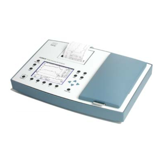
Indications for use The FONIX FP35 Hearing Aid Analyzer allows the user to test the characteristics of a hearing aid using coupler and optional real-ear measurements. These char- acteristics include: Frequency response, harmonic distortion, equivalent input noise, and compression. -
Page 6: Telecoil Outputs
1 .5 Measurement Inputs Probe Microphone: Crosstalk from reference microphone: < -80 dB Crosstalk from coupler microphone: < -80 dB Reference Microphone: Crosstalk from probe microphone: < -80 dB Crosstalk from coupler microphone: < -80 dB FONIX FP35 Maintenance Manual... -
Page 7: Harmonic Distortion Analyzer
1 .6 Harmonic Distortion Analyzer Type 2nd, 3rd, and 2nd + 3rd = Total Resolution 0.1 percent 1 .7 Available Tests Automated test sequences: ANSI S3.22-1996, ANSI S3.22-2003, IEC 60118-7:1994, JIS:2000, ISI Additional Coupler Tests: Coupler Multicurve, Coupler Target, Coupler Ear Real-ear Test Screens: Audiogram Entry, Insertion Gain, Real-ear Unaid- ed &... -
Page 8: Printer, External
5-85% humidity (non-condensing) 1 .14 Guarantee The FONIX FP35 Portable Hearing Aid Analyzer and its accessories are guaraanteed to be free from manufacturing defects which would prevent the products from meeting these specifications for a period of one year from date of purchase. -
Page 9: Chapter 2: Specification Test Procedure
Chapter 2: Specification Test Procedure 2 .1 Source Frequency Accuracy Instrument Required: Frequency counter accurate to 0.1 percent and capable of mea- suring 1000Hz. Setup: Enter the Coupler Multicurve screen of the FP35 analyzer and present a static pure-tone signal with a 100 dB SPL input level at 1000 Hz. Connect the frequency counter to the internal speaker jack. -
Page 10: Attenuator Accuracy
FP35 sound chamber. Place the FP35 coupler microphone so that its grill is facing the sound level meter micro- phone’s grill and is 1/8" away from it. Leave the chamber lid open and make sure the room is very quiet. FONIX FP35 Maintenance Manual... -
Page 11: System Equivalent Input Noise
Measurements: Starting at 200 Hz, measure the RMS levels at the reference point with both systems for each puretone frequency. They should agree within the tolerance of the sound level meter plus the tolerance of the FP35 analyzer. See Section 2.3. 2 .6 System Equivalent Input Noise Coupler Channel Setup: Insert the coupler microphone into an HA-1 coupler. - Page 12 FP35 analyzer. Set the composite noise reduction to 16X, turn off the reference mi- crophone, and set the output limit to 140 dB SPL. Set the source type to Composite and set the source amplitude to OFF. FONIX FP35 Maintenance Manual...
- Page 13 Measurements: Set the sinewave generator to produce a tone at 200 Hz with the volume control position as noted in step 2 of the equipment test above. Start the spectrum analysis measurement with the FP35 analyzer. The output at 200 Hz is the crosstalk measurement.
-
Page 15: Chapter 3: Calibration
Chapter 3: Calibration 3 .1 Introduction There are several different calibration procedures available on the FP35: Hardware calibration, system calibration, and microphone calibration. The hardware calibra- tion is performed at the factory using a "hardware calibration fixture." This type of calibration only needs to be done at the factory when the analyzer is manufactured or after a major repair or upgrade. -
Page 16: System Calibration
1. Press [MENU] from the Opening Screen to enter the Default Settings Menu. 2. Press [NEXT]. 3. Use the arrow keys to set the USER LEVEL to ADVANCED. 4. Press [EXIT] to return to the Opening Screen. FONIX FP35 Maintenance Manual... - Page 17 5. Press [F3] to enter the Coupler Multicurve Mode from the Opening Screen. 6. Use [F4] to choose NORM. 7. Press [MENU]. 8. Set REF MIC to OFF, if necessary, using the arrow keys. (This menu item will not appear on all analyzers.) 9.
- Page 18 MIC PORT to EXTERNAL. (This setting will not appear on all analyzers.) 5. Press [EXIT] and [MENU] again to refresh the menu selections. 6. Use the arrow keys to set DISPLAY to GAIN, NOISE RED (TONE) to 16X, and FONIX FP35 Maintenance Manual...
- Page 19 REF MIC to ON. 7. Press [EXIT] to return to the Coupler Multicurve Screen. 8a. If you are using an old style (legacy) probe microphone set, locate the cali- bration clip and fasten it to the edge of the reference microphone. Insert a fresh probe tube through the tube on the clip until the tip of the probe is at the center of the reference microphone grill as shown in Figure 3.4.3A.
-
Page 20: Microphone Calibration
The adapters come stan- dard with the analyzer. You can purchase additional adapters and a sound calibrator from the factory. (Sound calibrators are special orders and may not be immediately FONIX FP35 Maintenance Manual... - Page 21 available for purchase.) • Sound calibrator such as a QC-10 (all calibrations) • 14 mm-to-1 inch microphone adapter (coupler microphone calibration) • Rectangular reference microphone adapter (rectangular reference micro- phone on integrated probe microphone). • Calibration clip (legacy probe microphone) Sound calibrator(QC-10) 14 mm-to-1 inch microphone adapter calibration clip Figure 3 .5 Microphone calibration Rectangular reference equipment . microphone adapter 3 .5 .1 Calibrating the Coupler Microphone This procedure describes how to calibrate the coupler microphone. (On FP35 ana- lyzers manufactured before November 2008, the coupler microphone was also used as a reference microphone during real-ear measurements.) 1.
- Page 22 See Figure 3.5.2A. You can use a rubber band to hold the mi- crophone onto the calibrator, if necessary. See Figure 3.5.2B. Turn on the sound calibrator. FONIX FP35 Maintenance Manual...
- Page 23 9. Use the arrow keys to select “Custom Reference Mic Cal.” 10. Press [START/STOP] to start the calibration. 11. Use the up/down arrow keys to adjust the “MEASURED dBSPL” until it matches the output of the calibrator. Pressing the keys briefly will result in 0.1 dB chang- es.
-
Page 24: Insert Earphone Calibration
12. Press [F5] to store the calibration. 3 .6 Insert Earphone Calibration Before you can perform RECD or audiometric measurements, it is necessary to calibrate the insert earphone(s) that you will be using. The calibration for the insert earphones is FONIX FP35 Maintenance Manual... - Page 25 based on the ANSI S3.6-1996 specifications. There is no need to specifically cali- brate individual HL levels because the following calibration procedure provides a sufficiently stable reference. 3 .6 .1 RECD coupler setup 1. Insert the insert earphone into the “earphone” jack on the back of your ana- lyzer.
- Page 26 2. Select “Cal Left (Single) Ins. Earphone” using [] if necessary. 3. Press [START/STOP] twice to perform the calibration. 4. If you’re only using one earphone, skip to step 8. Otherwise, proceed. 5. Set up the right insert earphone for calibration as described above. FONIX FP35 Maintenance Manual...
- Page 27 6. Use [] to select “Cal Right Ins. Earphone.” 7. Press [START/STOP] twice to perform the calibration. 8. Press [F5] to save the insert earphone calibration. 9. Press [EXIT] to exit Earphone Calibration Screen. 3 .6 .5 Erasing the insert earphone calibration If you want to set the calibration to be electrically flat to allow you to use the “ear- phone”...
-
Page 29: Chapter 4: Circuit Description
Chapter 4: Circuit Description 4 .1 System Overview The FP35 is a hearing aid analyzer capable of measuring the frequency response and distortion of a hearing aid using coupler or real-ear measurements. Two input chan- nels are available: one for the coupler microphone and, optionally, one for a probe microphone. -
Page 30: Cpu
CPU Supervisor: U11 supplies the power-on reset for the CPU and other circuits. CPU Chip: The KU80386EX CPU(U12) includes the following integrated peripherals: • 386SX type CPU • Interrupt Control Unit. We’re using 5 of its external interrupts. It also has internal interrups going to other internal peripherals. • Three general purpose timers • Two Asyncronous Serial Ports • Two DMA Controllers • A Syncronous Serial Port • A Chip Select unit. We’re using five of its chip selects. FONIX FP35 Maintenance Manual... - Page 31 • General Purpose I/O pins. We’re using 13 of them. • A Watchdog Timer which is connected to the Non Maskable Interrupt pin. • JTAG port. CPU Bus: The following lines on the 386EX comprise the CPU Bus: • BLE, BHE, and A1 through A25 are the address bus • D0 through D15 are the data bus. • RD, WR, UCS, CS0, CS3, CS4, and CS6 are the control Bus. I2C Port: A standard I2C two line syncronous communication bus is implemented by general purpose lines P2.1(I2CSCL) and P2.2(I2CSDA) of the 386EX. Quiet Bus: The 386EX syncronous serial transmit pins(STXCLK, SSIOTX) and P1.0(SRLATCH) are used to implement the “Quiet Bus”.
-
Page 32: Cpld
• The Chip Selects on CPLDSEL and LCDFLY. Board Identification Circuit: Starting with the –08 board, the software needs to know which board is installed so that it can be adapted for that board revision. The BID1 and BID2 signals provide the identification. FONIX FP35 Maintenance Manual... - Page 33 BID1 = +5V BID2 = +5V : Rev –07 board or below BID1 = 0V BID2 = +5V : Rev –08 board, Rev –12 board BID1 = +5V BID2 = 0V : Rev –09 board, Rev –10 board and Rev –11 board BID1 = 0V BID2 = 0V : <future expansion of ID>...
- Page 34 While the Fujitsu printer can be operated with the older Seiko printer circuit in place (as long as the Seiko printer itself is not attached), normally the Seiko circuits will not be installed on the mainboard. FONIX FP35 Maintenance Manual...
- Page 35 The CPLD must be programmed for the printer that is being used. The Fujitsu printer requires at least a rev –11 main board. The Fujitsu printer also requires newer software (V6.10 or higher) which provides support for the new printer. When the Fujitsu printer is used, a 40pin connector J16 on the main board is used to attach the printer board.
-
Page 36: Signal Source
The gain of the amplifier is set to 16.07 dB (6.36x) for the 12V power supply, and 19dB (8.9x) for the 15V power supply by R90 and R91. C162 helps to prevent the speaker amplifier from oscillating and reduce sensitivity FONIX FP35 Maintenance Manual... - Page 37 to RF. R113 and C124 are a snubber circuit used to prevent the speaker amplifier from oscillating due to the inductive load presented by the speaker. R83 sets the peak current limit for the output of U26 (1.2amp for the 12V power supply, and 1.75amp for the 15V power supply).
- Page 38 C184,C185,C205 and C206 are used to provide additional RF protection. They are located near U25 and U27. R160,R161 and R162,R163 set the gain of the external line input buffers to 1x. The ground reference return of the FONIX FP35 Maintenance Manual...
-
Page 39: External Microphone Adapter Board
buffers is separately returned to the J9 jack to minimize ground noise getting into the signals. C156 and C157 are used to prevent U25B and U27B from oscillating and to reduce sensititive to RF. C170 and C171 decouple the outputs of the buffers to reduce pops and clicks that might occur when selecting the signals. - Page 40 U34 and U35 when there is no external microphone board installed. Frye microphones provide calibration and identification information via a Dal- las memory device located in the microphone connector. This signal (MIC_ID) is provided on pin 5 of J2 (pin 9 on J15). D37 is used to protect pin 5 of J2 from static discharge.
- Page 41 static or RF protection for the MIC_ID signal on J15 pin 9 as the protection is located on the separate external microphone adapter board. The Mic_ID signal requires two additional design requirements. It must have a series load for impedance matching (reduces ringing on the line), and it must be protected from the user inadvertenly plugging the FP35 power supply into the microphone connector.
- Page 42 The probe prescaler works similar to the coupler prescaler except that the probe pr- escaler has an additional probe equalizer circuit. The probe equalizer compensates for the probe tube on the probe microphone (roughly 6 dB per octave from 100 Hz to 8 KHz). FONIX FP35 Maintenance Manual...
-
Page 43: Power Supply
The 24 dB prescaler portion of the probe prescaler works just like the coupler pres- caler. The one exception is the feedback capacitor on U21A which is increased to 56 pf to reduce the sensitivity to high frequencies (creates a 16 KHz low pass filter). The coupling capacitor, C57, between the 24 dB prescaler and the 12 dB attenuator stage is changed to 3.3 nF, and the attenuator resistors are also reduced a bit. - Page 44 R91 and R51 are also changed to increase the gain of the speaker amplifier to 19 dB (8.9x) in order to make use of the extra power available with the ±15V supply. R83 is also changed to increase the current limit cut-out on the speaker amplifier to 1.75 Amp. FONIX FP35 Maintenance Manual...
-
Page 45: Standard Daughter Board
The Board ID resistors are also changed to identify the mainboard as a rev –12 board so that the software can recognize the hardware changes. 4 .8 Standard Daughter Board Refer to the FP35 Mono Daughter Board Schematic for the following discussion. The daughter board connects to the Main Board through J3. - Page 46 (V6.10 or higher) which provides support for the new printer. When the Fujitsu printer is used, a 40pin connector on the main board is used to attach the printer board. The Fujitsu printer board contains a motor controller and a head con- trol circuit for the printer. FONIX FP35 Maintenance Manual...
- Page 47 The Fujitsu printing is mapped from the screen as 3x3 printer dots for each screen pixel (three printer lines for each screen column). Printing is done from top to bot- tom left to right. The printout is turned 90 degrees from the screen layout to maxi- mize the print size.
- Page 48 (AEN1/ and AEN2/). U5 and U6 are used to buffer and control the strobe lines. The printer requires special control of the strobe lines which will be described later. The strobe liens are driven by the CPU via the CPLD. The CPLD is used as a simple output FONIX FP35 Maintenance Manual...
- Page 49 latch. The strobe lines are feed through the RF suppression circuits (L8->L14 and C20->C26) and Zeners Z7->Z13 are used to protect U5 and U6 from static. The pull-down resistors (R30->R36) are used to keep the strobe lines off when not in use.
- Page 50 The value selected is the number of times that each segment is "burned". If a print den- sity of "7" is selected, then the 555 timer will be triggered 7 times for each segment burn. The more burns that are triggered, the darker the print will be. FONIX FP35 Maintenance Manual...
- Page 51 The trade-off of darker print is a longer print time since the print is extended by the number of repeated burns. Too many burns will also cause thermal bleeding on the paper. The exact density to use is dependant upon the type of paper (high, medium or low sensitively) and the desired darkness of the print by the user.
- Page 52 Once a line has been fully burned, the data in the print head shift register is transferred to the printer head latch by strobing the Data Latch line. At the same time, the Segment FONIX FP35 Maintenance Manual...
- Page 53 burn method that was previously saved during the SSIO transfer is transferred to the segment print routine. The segment print method is used to determine which code path will be used to print the screen data that was transferred to the printer. The data will remain in the printer latch for 12 steps of the printer stepper motor.
- Page 54 Normal print time for most screens is about 8 to 10 seconds assuming standard paper, density setting at 7, head temperature between 30C and 50C, and printing a typical screen with graph data. FONIX FP35 Maintenance Manual...
-
Page 55: Chapter 5: Service And Repair Guide
Chapter 5: Service and Repair Guide Opening the FP35 for service To expose the component side of the Main board, turn the unit upside down and remove the four screws on the aluminum bottom panel. Be sure to use these screws with the lockwashers when you reattach the bottom panel. -
Page 57: Chapter 6: Cleaning
Chapter 6: Cleaning For your safety, disconnect the FP35 power supply from the mains power while cleaning. Wipe the FP35 case with a slightly moist but not dripping soft cloth. Use plain water or water with mild dishwashing detergent. Wipe away any detergent with a slightly moist cloth, then dry the FP35. - Page 58 FP35 Safety Markings FP35 serial number label (on bottom of unit) 0 0 8 6 VIDEO LINE IN SPEAKER EARPHONE CONTRAST RS232 PRINTER POWER FP35 rear panel FONIX FP35 Maintenance Manual...
-
Page 59: Chapter 7: Safety
Chapter 7: Safety Warning on AC power cord for medical grade power supply: GROUNDING RELIABILITY CAN ONLY BE ACHIEVED WHEN THE EQUIPMENT IS CONNECTED TO AN EQUIVALENT RECEPTACLE MARKED HOSPITAL ONLY OR HOSPITAL GRADE. Safe operation of the FP35 absolutely depends on the integrity of the safety earth connection at your mains outlet. -
Page 60: Connection Of Peripheral Equipment To The Fp35
Please contact Frye Electronics at support@frye .com if you have any questions about what equipment can be connected safely to the analyzer. The FONIX FP35 Test System is equipped with USB and RS232 connections that will allow you to connect to a personal computer and exchange data. You will also need a software program, such as WinCHAP, on your Windows computer that can commu- nicate with the analyzer. -
Page 61: Electromagnetic Compatibility
See www.frye.com for details. Failure of the hardware connection or software program could result in incorrect transfer of data. Connecting the FP35 to other equipment could result in previously unidentified risks to patients, operators of third parties. The installer should identify, analyze and control these risks. -
Page 62: Disconnection Of The Fp35 Analyzer
7 .6 Disconnection of the FP35 Analyzer The means of isolating the FP35 Analyzer from the supply mains is to unplug it. FONIX FP35 Maintenance Manual... -
Page 63: Chapter 8: Electromagnetic Compatibility
Printer 25 conductor shielded IEEE 1284 Accessories with which the FP35 complies with IEC 60601-1-2 Description Manufacturer Model/Part Number Coupler Microphone Frye Electronics, Inc. M367 Coupler/Probe Microphone Set Frye Electronics, Inc. M357 Insert Earphone LCD VGA monitor Warning: The FP35 should not be used adjacent to or stacked with other equipment. If adjacent or stacked use is necessary, the FP35 should be observed for normal operation in the configuration in which it will be used. - Page 64 Power frequency magnetic (50/60 Hz) fields should be at levels Magnetic field characteristic of a typical commercial or hospital IEC 61000-4-8 environment. Note Ut is the a.c. mains voltage prior to application of the test level. FONIX FP35 Maintenance Manual...
- Page 65 Guidance and manufacturer’s declaration – electromagnetic immunity The FP35 is intended for use in the electromagnetic environment specified below. The customer or the user of the FP35 should assure that it is used in such an environment. Immunity test IEC 60601 test level Compliance Electromagnetic environment level...
- Page 66 NOTE 1 At 80 MHz and 800 MHz, the separation distance for the higher frequency range applies. NOTE 2 These guidelines may not apply in all situations. Electromagnetic propagation is affect- ed by absorption and reflection from structures, objects and people. FONIX FP35 Maintenance Manual...
Need help?
Do you have a question about the FONIX FP35 and is the answer not in the manual?
Questions and answers