Table of Contents
Advertisement
Quick Links
A l l t e s t I n s t r u me n t s , I n c .
5 0 0 C e n t r a l A v e .
F a r mi n g d a l e , N J 0 7 7 2 7
P : ( 7 3 2 ) 9 1 9 - 3 3 3 9
F : ( 7 3 2 ) 9 1 9 - 3 3 3 2
a l l t e s t . n e t
s s a l e s @ a l l t e s t . n e t
T h e t e s t & me a s u r e me n t
e q u i p me n t y o u n e e d a t
t h e p r i c e y o u w a n t .
A l l t e s t c a r r i e s t h e w o r l d ' s l a r g e s t s e l e c t i o n o f
u s e d / r e f u r b i s h e d b e n c h t o p t e s t & me a s u r e me n t
e q u i p me n t a t 5 0 % t h e p r i c e o f n e w .
O O u r e q u i p me n t i s g u a r a n t e e d w o r k i n g , w a r r a n t i e d , a n d
a v a i l a b l e w i t h c e r t i f i e d c a l i b r a t i o n f r o m o u r i n - h o u s e s t a f f
o f t e c h n i c i a n s a n d e n g i n e e r s .
• 1 0 + f u l l t i me t e c h n i c i a n s w i t h o v e r 1 5 0 y e a r s o f
s p e c i a l i z a t i o n
• 9 0 d a y w a r r a n t y & 5 d a y r i g h t o f r e t u r n o n a l l
e q u i p me n t
• • 1 - 3 y e a r w a r r a n t i e s f o r n e w a n d
p r e mi u m- r e f u r b i s h e d e q u i p me n t
• E v e r y u n i t t e s t e d t o O E M s p e c i f i c a t i o n s
• S a t i s f a c t i o n g u a r a n t e e d
Y o u h a v e p l a n s , w e w i l l h e l p y o u a c h i e v e t h e m.
A n y p r o j e c t . A n y b u d g e t .
t
G e t a q u o t e t o d a y !
C C a l l ( 7 3 2 ) 9 1 9 - 3 3 3 9 o r e ma i l s a l e s @a l l t e s t . n e t .
Advertisement
Table of Contents

Related Manuals for Tektronix SG 504


Summary of Contents for Tektronix SG 504
- Page 1 T h e t e s t & me a s u r e me n t e q u i p me n t y o u n e e d a t t h e p r i c e y o u w a n t . A l l t e s t I n s t r u me n t s , I n c .
- Page 2 COMMITTED TO EXCELLENCE PLEASE CHECK FOR CHANGE INFORMATION AT THE REAR OF THIS MANUAL. SG504 LEVELED SINE WAVE GENERATOR INSTRUCTION MANUAL Tektronix, Inc. P.O. Box Serial Number 97077 Beaverton, Oregon First Printing JAN 1976 Revised AUG 1981 070-1632-01 //manolt"an "q...
- Page 3 Copyright �1976, 1 978 Tektronix, Inc. All rights reserved. Contents of this publication may not reproduced in any form without the written permission of Tektronix, Inc. Products of Tektronix, Inc. and its subsidiaries are covered by U.S. and foreign patents and/or pending patents.
-
Page 4: Table Of Contents
SG 504 TABLE OF CONTENTS Page SECTI O N 1 O PERATING INSTRUCTIONS 1 - 1 French Version German Versi on Japanese Version SECTI ON 2 SPECIFI CAT I O N AND PERFORMANCE C HECK The remaining portion of this Table of Contents lists servicing instructions that expose personnel to hazardous voltages. - Page 5 SG 504 SAFETY SUMMARY The fol l ow i ng text contains a two-part summary of general safety precautions that m ust be observed d uri ng a l l phases of operation, service, and repai r of this i nstrument.
- Page 6 SG 504 Use the Proper Power Cord Use only the power cord and connector speci fied for the power module. Use only a power cord t hat is i n good condition. For detai l ed information on power cords and connectors, see the power mod u l e manual.
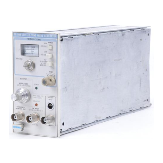
- Page 7 . .. , · � ..� . \ :: ..· · · · , �· -· 1.632-01 SG 504 Leveled Sine Wave Generator. 198 0 RE V B MA R h ... tp://manoman.sqhill com...
-
Page 8: Operating Instructions
Controls and Conn e ctors Refer to Fig. 1 -2. Even though the SG 504 is f u l l y The front-panel FREQUENCY M O N I TO R OUT con cal i brated and ready t o u se, the functions and actions of nector provides at least a 0.3 V peak-to-peak signal at the... - Page 9 Con nect the properly terminated output head to the device under test. the front-panel light UNLEVELED If the SG 504 is left in a power on state for long comes on, turn the O control AMPLITUDE periods of time, turn the O U TP U T AMPLI TUDE counterclockwise until the light goes out.
- Page 10 Operati ng l nstructions-SG 504 FREQUENCY MHz Calibrated tape dial indicates output fre quency, In two ranges. RANGE HIGH Pushbutton Selects high output range. RANGE LOW Pushbutton Selects low output range. COARSE Control Selects outpUt frequency within the desired fre- quency range.
- Page 11 R Is 25 n. (C) Capacitive load where .capacitance does not change with frequency. 1632-06 Fig. 1-3. Equivalent circuits for SG 504. 50-ohm coaxial cable and various terminations. 1- 4 REV B. AUG 1978 http.//manoman sqh II.com...
- Page 12 When frequency accuracy better than 2% is required, When operating the SG 504, al ways consider the total con nect a frequency counter to the FREQUENCY l oad impedance and its effect on the output amplitude.
-
Page 13: Specification And Performance Check
Electrical Characteristics are verified b y com plet i n g SG 504 has been cal i brated at an am bient tem perature the Performance Check i n this manual. Items listed i n t h e between +20°C and +30°C and is operati ng at an am bient... - Page 14 S pecification and Performance Check-SG 504 Table 2-1 (cont) Characteristics Performance Requ irements Supplemental I nformation Fm I nput Deviation Deviation sensitivity: ±9 V produces from to ±0.4% ±0. 05% d eviation of carrier, depending o n output frequency. Frequency Range De to kHz.
- Page 15 The electrical characteristics i n this section are val i d facilitate the procedure. M ost of these are available from only if t h e SG 504 i s calibrated a t a n ambient temperature Tektronix, I nc. and can be ordered through your local of +20°C to +30°C and operated at an am bient...
-
Page 17: Warning
Pr e limi nary Proc e du r e .1 v Volts/Div 1 . Ensure that all test equ i p ment and the SG 504 under test are suitabl y adapted to the l i ne voltage to be applied. Variable... - Page 18 SG 504 U N L EVELED lig ht remains off. i. Set the SG 504 OUTPUT A M P L I T U D E control to 0.5. Set the differential comparator deflection factor for .1 V/div.
- Page 20 S pecifi cation and Performance Check-SG 504 q. Repeat parts o and p of t h i s step for the 0.5 volt g. Push in the SG 504 H I G H RANGE pushbutton. setting of the SG 504 O UTPUT AMPLI TUDE control;...
- Page 21 Use Table 2-5 as reference for verification ott he six frequency check points. d. Set the SG 504 internal slide switch, S 1 90, to the 6 M H z posit i on. See Fig. 3-1 for switch l ocation.
- Page 22 The j . Connect the SG 504 O utput Head via bnc female to difference from the maxi m u m n u m ber wil l be a positive...
- Page 23 COARSE control e. Set the SG 504 O U T P U T A M PL I T U D E control to 1 .0 clockwise from 245 M Hz to 550 M Hz, as i ndi cated on the volt, 2.0 volts, and 3.5 volts.
-
Page 24: Adjustment
This adjustment procedure is to be used to restore the The test equi pment l i sted i n Table 3- 1 , o r equ i valent, is SG 504 to ori gi nal performance specifications. Adj ust requi red for adjustment of the SG 504. Specifications... - Page 25 Adjustment-SG 504 Table 3-1 (cont) LIST OF TEST EQUI PMENT REQUIREMENTS Performance Description Requirements Appllcatlon Exam ple Counter Maxi m u m Frequency, 500 kHz; Reference frequency ac- T EKTRO N I X DC 501 Digital Period Avg mode capable to curacy check.
- Page 27 Di sconnect the bnc cable of the O utput Head from ust--1 8 V adj , R590, for a meter reading of 1 8 the SG 504 front-panel connector; connect a X1 0, 50 volts. See Fig. 3-1 for adjustment l ocat i o n .
- Page 28 6. Che c k Output of 0. 05 MHz and 6 MHz Re f e r e nc e 3-1 for l ocation. a. Con nect the SG 504 O utput Head, t hrough a 50 precision termi nation, to the m i nus ( ) i nput of the differential com parator.
- Page 29 5.5 divisions. j. Adjust-.5 V P-P Ampl, R270, so the corners of the f. Set the SG 504 i nternal slide switch, S 1 90, to the ideal ized waveform are aligned as i l l ustrated i n Fig. 3-3.
- Page 30 Set the SG 504 OUTPUT AMPLITUDE control to 5.5. Push in the LOW RANGE p ush button. d. Rotate the SG 504 COARS E control u ntil the d i al tape i ndi cates 245 at the cursor l i ne.
- Page 32 Slowly rotate the SG 504 COARSE control from f. Repeat parts c and d of this step. 1 050 M H z and observe if the SG 504 UN LEVELED li ght turns on. If the l ight is l it, readj ust High Band, C75, counterclockwise until the l i ght j u st turns off.
- Page 33 Level is set to 0 dBm and RF dB is set to 30. o. Set the spectrum analyzer Reference Level to j. Push in the SG 504 H I G H RAN G E pushbutton. +20 d Bm and RF d B to 50.
- Page 34 LOW AND HIGH RANGE FREQUENCY ACCURACY a. Repeat parts a throug h g of Step 1 3. Be certai n that All owable Deviation the SG 504 F I N E control i s set to 0 ( centered). from Frequency SG 504 Frequency...
- Page 35 T i g hten the hex-type set screws one at a time w h i l e c. Adjust the spectrum analyzer Frequency Coarse making certai n that t h e SG 504 450 M H z sig nal a n d the control to horizontally center the 750 MHz marker on the spectrum analyzer 450 MHz marker coi n cide.
- Page 36 Do not disturb the approximate 1 . 2 volt setting of the Consult the power sensor calibration chart to deter SG 504 OUTPUT AMPLITUDE control, as set in part mine the calibration factor correction points for the c of this step; otherwise, an incorrect deviation power meter front-pane/ calibration factor setting.
- Page 38 SG 504 F R EQ frequency band. Note and record the maxi m u m and M O N I T O R O U T connector.
-
Page 39: Maintenance An D Inte Rfacing Info Rmatio N
INFO RMATIO N Table 4-1 Preventive Maintenance POWER LIM ITS FOR OSCILLATOR There special preventive mai ntenance procedu res that apply to the SG 504. Refer to the power SG 504 module i nstruction manual general preventive Frequency Range Dial Setting Power Limits maintenance proced ures and i n structions. - Page 40 The metal tabs are connected to the collector I f the SG 504 is not operat i ng properly, and cali brati on termi nal. does not correct the problem, t hen an O ut put Head malfu nction i s the l i kely cause and should be checked for a poss i b l e defect.
- Page 41 Performance Check and Adjustment Procedure will prove ohms i s val i d only for m A of measurement cu rrent . ) useful i n trou bleshoot i n g the SG 504. B , A U G i 978 R EV...
- Page 42 F i g. 4- 1 . I f the SG 504 i s to be shi pped to a Tektron i x Service The i nstrument i s not wi red with these connections. The Center for service or repair, d i scon nect the Output Head fol l ow i n g connections apply to the SG 504.
- Page 43 Maintenance and I nterfacing l nformatlon-SG 504 Function Function Remarks Remarks User i nstalled Frequency Monitor O utput Ground Frequency Monitor Output User i nstalled Frequency Monitor Output Ground User installed Signal Source User i n stalled FM I nput Ground...
-
Page 44: Circuit D Escription
General go negative. This i n creases the amount of back b i as on the The SG 504 consists of a .05 MHz or 6 MHz Hartley varactor d i odes, red ucing their capacitance. This action am plitude reference osci l l ator, two transistorized cavity raises the output frequency. - Page 45 Circuit Descri ption-SG 504 the emitter power supply. The output from the buffer i s If the output signal i ncreases due to decreased l oading, taken from t h e col l ector o f 0 1 20, then fed throug h a l ow...
- Page 46 Circuit Descrlption-SG 504 A second protection circuit prevents excessive signal -26 V, 0650 conducts and triggers 0660 on with the same voltages from developing if the signal cable to t he output results. O n ce 0660 is t u rned on, the i nstrument m ust be head i s discon n ected w h i l e the control cable i s con n ected.
-
Page 47: Opti Ons
Section 6-SG 504 O PTI O N S N o options are avai l able at this t i m e. � 1 http://man n.sqh1ll.com... - Page 48 If a part you have ordered has been replaced with a new or improved part, your local Tektronix, Inc. Field Office or representative w i l l contact you concern ing any change in part mber.
- Page 49 Replaceable Electrical Parts-SG 504 C ROSS I N DEX- M F R . C O D E N U M B E R TO M A N U FACTU R E R M f r . Code M a nufacturer...
-
Page 50: Replaceable Electri Cal Parts
Replaceable Electrical Parts-SG 504 M fr Tektro n i x Serial / Model N o . Mfr P a rt N u m ber C k t No. Part N o . Dscont Name & Description Code 6 70 - 3 4 0 3 -00... - Page 51 Replaceable Electrical Parts-SG 504 Tektronix Seri a l / M o d e l No. Mfr Part N u m ber C k t No. Part N o . E f f Dscont N a m e & Description Code...
- Page 52 Replaceable Electrical Parts-SG 504 M f r Seria l / Model N o . Tektro n i x N a m e & Descri p t i o n Code Mfr Part N u m ber Dsco n t C k t No.
- Page 53 Replaceable Electrical Parts-SG 504 Tektronix S e r i a l / Model No. Dscont Name & Description Code M f r Part N umber Ckt No. Part No. Q 3 5 5 1 5 1 -0 1 90-00 TRANS I STOR : S IL I CON , NPN...
- Page 54 Replaceable Electrical Parts-SG 504 M f r Seria l / Model N o . Tektro n i x Mfr Part N u mber Code Dsc o n t N ame & Description Part N o . C k t N o .
- Page 55 Replaceable Electrical Parts-SG 504 Tektronix Seria l / M o " e l No. Part N o . Dscont N a m e & Descr i p t i o n Code Mfr Part N u mber C k t...
- Page 56 Replaceable Electrical Parts-SG 504 Tektr o n i x Serial / M o d e l N o . Name & Desc r i p t i o n C o d e Mfr P a r t N u mber C k t No.
- Page 57 OPT I ON A L ACCESSO R I ES 015-0221-00 CAPACITOR ,CPLG : 0 . 047UF , BNC 80009 015-0221-00 CABLE 175-1869-00 ASSY , RF : SO COAX , 4 . 0 80009 175-1869-00 REV. A AUG 1 978 SG 504 http.//manoman sqh II.com...
-
Page 58: I Ag Rams A N D Circu I T Board I Llu Strat I O N
Abbreviations are based on A N S I Y1 . 1 - 1 972. Other A N S I standards that are used i n the preparation of d iagrams by Tektronix, I n c . are: Y 1 4 . 1 5, 1 966 Drafting Practices. - Page 59 Ulll L. EVELEC l.. A MP Oll.. I VE:i.� Q l 70 Q."\()C; Q�l t; LEV l: L I NG, AMPL I F I ER. - 18V PllJ DIODE S H U llJT S U Fl=" E P $E ll.. I ES 01001!.
- Page 60 r-·- : . - - - ·- - ·- - · - 531A .-- - · ---- ... --· - - · - ·· - -- -· - · - ·- - --- - · · -·· - · ---- --1�- - -·...
- Page 61 :- J4 1 C6t' • • -1 :,.. C 9 7 C 99 L�B � • • .• � :::: :: 1 CJ , . • "' f!� :5 � ..; '\... iJ_6• t- · � . . -:-- ..::. . - ,..
- Page 62 The voltages and waveforms shown on this diag ram were taken with the SG 504 O ut p ut H ea d con nected a n d i t s i n put term i n ated i nto 50 ohms. The i nternal slide switch, 51 90, w a s set to 6 M Hz. T h e...
- Page 63 A l M A I N &OAFlO P \ N SHUNT CURRENT � I C.. O l"!>O �l�l (Pio.I) 1.0 l'l'l. -'S!IO 415-IOSO I HI a no '5UP'PLY YR30 5 . b V l.OW C.2.0 FM INPUT Q l90, Q '2.ZO RIO+ CUIU.eNT �MUT- DOwi.I...
- Page 65 U 2 'l) O ( O V T P V T H EAD A5!> !'. M8L'1" ) MAJ "1 60Al2.D D IO D E P I N S H A P ER R. • SO II.J P "- � 1 . o;, 1c. NT P A U'2."l'5>...
- Page 66 The voltages shown on t h i s d i agram were taken with the SG 504 O ut p ut Head connected and its i n put termi nated i nto 50 ohms. The i nternal slide switch, S 1 90, was set to 6 M Hz. The front-panel controls were set as fol lows: RAN G E switch to R EF, FI N E control to and OUTPUT A M P L I T U D E control to 5.5.
- Page 67 Q\10 it.F �70 <:170 Gll'l. O C VR.R.eNT &I A � C> & HIGH 8UrF�R CURRENT LOW BUFFER CURRENT Q5'!.0 S'l. O C. - 18V C'!.10 0 . 1 s�oA - --1 lnpul ""- Q 5�0 Grourd "'- � l<SOO Hl<!aH SVFF&ll.
-
Page 68: Replac Eabl E M Echa N I Cal Parts And
Following is an example of the indentation system Tektronix, Inc. Field Office o r representative. used in the description column. 1 2 3 4 5 Changes to Tektronix instruments are sometimes made to & Name Description accommodate improved components as they become available,... - Page 69 Replaceable Mechanical Parts-SG 504 C ROSS I N DEX-M F R . C O D E N U MBER TO M A N U FACTU R E R M f r . Code M a nufacturer A d d ress City.
- Page 70 Replaceable Mechanical Parts-SG 504 F i g . & I ndex Tektr o n i x Seria l / M odel No. 2 3 4 N a me & Desc r i p t i o n Code Mfr Part N u m be r P a r t N o .
- Page 71 Replaceable Mechanical Parts-SG 504 F i g . & M f r Index T e k t r o n i x Seria l / Model N o . M f r Part N u m be r E lf...
- Page 72 Replaceable Mechanical Parts-SG 504 F i g . & I ndex Tektro n i x Seri a l / M od e l N o . 2 3 4 Part N o . Dscont N a m e & Description...
- Page 73 SG 504...
Need help?
Do you have a question about the SG 504 and is the answer not in the manual?
Questions and answers