Table of Contents
Advertisement
Quick Links
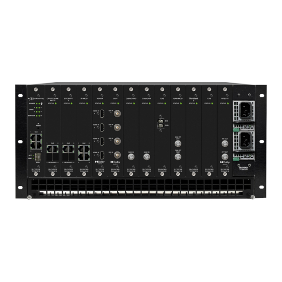
NX G SYST EM KIT
MODULAR IP DIGITAL VIDEO PLATFORM
STOCK #
MODEL NAME
6780
NXG-MFR
6781
NXG-CNTRL
6782
NXG-PS
Re v : 12 072 2
BL ONDE R TONGUE L AB O RATO RI E S, I N C. | IS O 9001:201 5 C E RT IFI ED | W W W.B L O N D E RTO N GU E. C O M
DESCRIP TION
Mainframe - 5RU Chassis; 12 Module Slots; 60 Gb Capacity Backplane with
Fans & Air Filter
Master Controller Module - Controls Entire Platform
Power Supply - (2) Required for Redundancy
All Righ ts Reserv ed. Specifications s ubj ect to chang e without not ice.
All trad emar ks are propert y of their r espective owners.
USER MANUAL
NXG PLATFORM
P / N: 6 5 1 2 4 7 0 00 A
Advertisement
Table of Contents

Related Manuals for Blonder tongue NXG SYSTEM KIT


Summary of Contents for Blonder tongue NXG SYSTEM KIT
- Page 1 USER MANUAL NXG PLATFORM NX G SYST EM KIT MODULAR IP DIGITAL VIDEO PLATFORM STOCK # MODEL NAME DESCRIP TION Mainframe - 5RU Chassis; 12 Module Slots; 60 Gb Capacity Backplane with 6780 NXG-MFR Fans & Air Filter 6781 NXG-CNTRL Master Controller Module - Controls Entire Platform 6782 NXG-PS...
- Page 2 RETURNING PRODUCT FOR REPAIR (OR CREDIT) A Return Material Authorization (RMA) Number is required on all products returned to Blonder Tongue, regardless if the product is being returned for repair or credit. Before returning product, please review our...
-
Page 3: Table Of Contents
NXG SYSTEM User Manual TABLE OF CONTENTS SECTION 1 – GENERAL & SAFETY INSTRUCTIONS ............4 SECTION 2 – PRODUCT SUMMARY ..................5 2.1 PRODUCT APPLICATION & FEATURES ......................5 2.2 PRODUCT SPECIFICATIONS ..........................6 2.3 SYSTEM OVERVIEW ............................7 2.4 PRODUCT PLATFORM BACKPLANE DESCRIPTION .....................9 SECTION 3 –... -
Page 4: Section 1 - General & Safety Instructions
å Do not use accessories or attachments not recommended by Blonder Tongue, as they may cause hazards, and will void the warranty. -
Page 5: Section 2 - Product Summary
2.1 PRODUCT APPLICATION & FEATURES APPLICATION The NXG System Kit, containing the Mainframe Chassis, Controller Module, and dual redundant, high reliability power supplies, is a powerful 5RU set up that allows for complete customization based on specific video processing and distribution needs. -
Page 6: Product Specifications
6 NXG SYSTEM User Manual 2.2 PRODUCT SPECIFICATIONS MASTER CONTROLLER SPECIFICATIONS INPUT / OUTPUT ALARMS / MONITORING / CONTROL Status LED Indicators for Power, DATA PORTS Temperature, Fans, and all network Gigabit 4x RJ45 GigE for IP Input or Output & connections Ethernet Control... -
Page 7: System Overview
NXG SYSTEM User Manual 2.3 SYSTEM OVERVIEW The following diagram displays an overview of a NXG System with a number of current modules installed. The diagram does not represent all current or future module options or combinations. SECURE IP DRM CLE ARQ AM / SECURE AES KEY... - Page 8 8 NXG SYSTEM User Manual 2.4 PRODUCT MODULE DESCRIPTION MASTER CONTROLLER MODULE Power LED: Blinking Red/Off = Voltages/currents are abnormal or 1 power supply AC ▶ is now plugged in. Solid Green = Voltages/currents are normal ▶ Temperature LED: Solid Red = Master Controller temperature is critically high. ▶...
-
Page 9: Product Platform Backplane Description
NXG SYSTEM User Manual 2.4 PRODUCT MODULE DESCRIPTION (CONTINUED) SFP+: 10 GbE data port used for distribution of IP streams and remote monitoring & control. POWER MODULES Right LED (AC) / Left LED (DC): Off = power not detected (Note: Check utility power input) ▶... -
Page 10: Section 3 - Installation & Power-Up
10 NXG SYSTEM User Manual SECTION 3 – INSTALLATION & POWER-UP 3.1 UNPACKING You will find the following items in the box: NeXgen Chassis (QTY=1) Anti-static wrist strap (QTY=1) ▶ ▶ 10 blank panels (QTY=2 bags of 5 each) ▶ Modules are user-installed circuit boards with exposed parts and contacts. -
Page 11: Section 4 - Connecting To A Pc/Laptop
NXG SYSTEM User Manual 3.2 INSTALLATION AND POWER-UP (CONTINUED) Install the appropriate input and output modules for your NeXgen application in any of the 12 slots. When possible space the input and output modules apart to maximize airflow. REMINDER: Before NXG-CCQD-24 module installation, don't forget to insert the CableCARDs into the module. Please see the NXG-CCQD-24 Manual for more information on installation. -
Page 12: Accessing The Gateway Via The Web Browser
12 NXG SYSTEM User Manual 4.2 ACCESSING THE GATEWAY VIA THE WEB BROWSER You must complete the steps described in Section 4.1 before proceeding as follows: Open a web browser on your computer (Chrome or Firefox is recommended) and enter the following URL address (http://172.16.70.1). The “Login” prompt (Figure 4.2a) will appear. -
Page 13: Section 5 - Platform Configuration
NXG SYSTEM User Manual SECTION 5 – PLATFORM CONFIGURATION 5.1 “STATUS” TAB “Status” (Figure 5.1) is a read-only screen which displays the general health of the platform, such as temperature, fan speed and status reporting. The information is provided as a quick way to monitor the system or assist with troubleshooting issues that may arise. - Page 14 14 NXG SYSTEM User Manual 5.1 “STATUS” TAB (CONTINUED) 155 °F 170 °F Temperature: Indicates one of the following, 68 °C 76 °C depending on the slot or component, in real-time: Master Controller: Temperature the Master ▶ Normal Temperature Normal Temperature Warning Warning Error...
- Page 15 The user can click on the “Auto-Refresh” checkbox to enable that function. See Section 5.6 for more information on types of messages. Reference: The two reference links under this section point to the Blonder Tongue website and a screen showing the RF Channel Lists.
-
Page 16: Streams" Tab
16 NXG SYSTEM User Manual 5.2 “STREAMS” TAB “Streams” (Figure 5.2) is a read-only screen which displays information on each stream configured within each module on the platform. Figure 5.2a - “System Stream Information” Module Name (Slot: #): Indicates the module's short name and what slot it is installed into within the platform. Stream: Displays the Source Stream Name. - Page 17 NXG SYSTEM User Manual 5.3 “SYSTEM” TAB (CONTINUED) Figure 5.3 - “System Configuration” - Full View MAC Address: the Media Access Control (MAC) Address is a read-only field that serves as a unique identifer assigned to the network. IP Address: the static IP address that is assigned to the unit, allowing the user to access it via the web interface.
- Page 18 18 NXG SYSTEM User Manual 5.3 “SYSTEM” TAB (CONTINUED) USER INTERFACE IP ACCESS RESTRICTION LIST (IP WHITELIST) This feature allows a user to restrict access to the Master Controller's web-based GUI by through an IP Whitelist. The IP Whitelist settings may be configured via the User Interface IP Access Restriction List section on the System of page or by a Configuration File upload available under the aforementioned heading.
- Page 19 NXG SYSTEM User Manual 5.3 “SYSTEM” TAB (CONTINUED) HTTP SSL KEY/CERTIFCATE UPLOAD User-supplied SSL Key: a user-supplied SSL key can be uploaded to the unit. User-supplied SSL Certificate: a user-supplied SSL certificate can be uploaded to the unit. SSL Key/Certificate Operations: the user can delete the current SSL data from the machine. Figure 5.3b - “System Configuration”...
-
Page 20: Front Panel" Tab
20 NXG SYSTEM User Manual 5.3 “SYSTEM” TAB (CONTINUED) General Purpose: User can set up the “IP Address”, “Subnet Mask”, and “Default Gateway” of the Command/ Control Port. Dedicated Front Port: User can set up the “IP Address”, “Subnet Mask”, and “Default Gateway” of the Dedicated Front Port for IP I/O use. -
Page 21: Module Configuration
NXG SYSTEM User Manual 5.5 MODULE CONFIGURATION After the hardware installation of any modules, go through the control panel and set up each module slot tab to configure your NXG application. Please refer to the individual user manuals of each module for in-depth configuration instructions. - Page 22 22 NXG SYSTEM User Manual 5.6 “TIME” TAB (CONTINUED) Figure 5.4c - “NTP Settings” NTP SETTINGS Enable NTP System Time Synchronization: Enable ( ) or Disable ( ) System Time Synchronization. Use Custom NTP Servers: Enable ( ) or Disable ( ) the Custom NTP Servers.
-
Page 23: Notification" Tab
NXG SYSTEM User Manual 5.7 “NOTIFICATION” TAB The “Notification” (Figure 5.5a, Figure 5.5b, Figure 5.5c and Figure 5.5d) settings on this screen are configurable and used for system events by sending out notifications to one or more email addresses. Figure 5.5a - “Notification Configuration” NOTIFICATION CONFIGURATION Enable Notifications: Enable ( ) or Disable (... - Page 24 24 NXG SYSTEM User Manual 5.7 “NOTIFICATION” TAB (CONTINUED) Direct (Bypass MTA): to bypass the Mail Transfer Agent (MTA), the user can set this to Enable ( ) in order to utilize direct-to-MX mailing without the use of an SMTP server. Username: set the username of the account for SMTP server authentication in order to send outgoing emails.
-
Page 25: Snmp" Tab
NXG SYSTEM User Manual 5.8 “SNMP” TAB The “SNMP” (Figure 5.6) settings on this screen are configurable and used for system events by sending out notifications to one or more email addresses. SNMP Configuration allows the user to configure the IP of an SNMP server and enable SNMP traps providing alerts. -
Page 26: Section 6 - Ip Input/Output Configuration
26 NXG SYSTEM User Manual SECTION 6 - IP INPUT/OUTPUT CONFIGURATION The “IP I/O” tab works in a very similar way to a discrete NXG-IP series module with some notable differences. The functionality only supports input (ingress) or output (egress) of single program transport streams. Both ingress and egress cannot be done concurrently. -
Page 27: Ip I/O: System" Sub-Tab
NXG SYSTEM User Manual 6.1 “IP I/O: STATUS” SUB-TAB (CONTINUED) Figure 6.1a - “Status” Tab - No Detected Issues In the section entitled “Module Information”, the following module-specific information is shown below: Serial Number: Indicates the serial number of the module installed. Software Version: Indicates the software version of the module. -
Page 28: Ip I/O: Input" Mode Sub-Tab
28 NXG SYSTEM User Manual 6.3 “IP I/O: INPUT” MODE SUB-TAB The “Input” mode allows a user to add and assign input streams to the selected IP port. NOTE: Clicking the arrow ( collapsed; expanded) beside each program will show or hide further choices or read-only data. -
Page 29: Available Resources
NXG SYSTEM User Manual 6.3.2 AVAILABLE RESOURCES The “Available Resources” table displays, in real-time, the remaining available resources after factoring out the current assigned streams. The resources being monitored are as follows: TS In: Displays the remaining Transport Stream (TS) available that may be input. -
Page 30: Input Stream Search Functions
30 NXG SYSTEM User Manual 6.3.5 INPUT STREAM SEARCH FUNCTIONS The list of streams which have been configured and added will show below the configuration area. Figure 6.3.5 - Input Stream List Search Functions The “Search” function is provided as a way to easily find a program within a list. This standard function is real-time, acting as a filter to isolate matches as the user types into the input field. - Page 31 NXG SYSTEM User Manual 6.4.1 ADD OUTPUT STREAMS CONFIGURATION (CONTINUED) Destination IP: User must enter the IP address of the receiving equipment. Multicast IP is only supported on the master controller front panel ethernet port to which the IP I/O functionality is bound Destination Port: User must enter the IP Port of the receiving equipment.
-
Page 32: Available Output Resources
32 NXG SYSTEM User Manual 6.4.2 AVAILABLE OUTPUT RESOURCES The “Available Resources” table displays, in real-time, the remaining available resources after factoring out the current assigned streams to the IP Output. The resources being monitored are as follows: # TS: Displays the total remaining available Transport Streams (TS). Up to 512 transport streams are supported for output through the Master Controller’s front panel ethernet ports. -
Page 33: Remove Configuration
NXG SYSTEM User Manual 6.4.3 STREAM LIST VIEWS (CONTINUED) Source Stream: Displays the Source Stream Name. Empty checkboxes ( ) are selectable to remove configured input streams, as detailed below. When the line is expanded, the following data ( ) for each program is shown: Output IP: Output IP address that the stream is assigned to. -
Page 34: Section 7 - Update, Troubleshoot, And Maintenance
34 NXG SYSTEM User Manual SECTION 7 – UPDATE, TROUBLESHOOT, AND MAINTENANCE 7.1 “LOG” TAB The “Log” (Figure 7.1) screen displays system log messages. The following is a description of the changeable parameters for this screen as well as a description of the message filter types. Figure 7.1 - “System Log”... -
Page 35: Firmware Update" Tab
Click the “Firmware Download Site” linked button and then click through the following folders to view the list of NXG modules: “BLONDER TONGUE” > “N” > “NEXGEN GATEWAY” NOTE: There is a check of the file name versus module ID to eliminate a user inadvertently updating any modules with incorrect files. -
Page 36: Admin" Screen
36 NXG SYSTEM User Manual 7.3 “ADMIN” SCREEN The “Admin” (Figure 7.3) settings allow a user to change or modify the Username and Password values for the unit while logged in. To access this screen, click the “Admin” link at the top right corner as shown below. Figure 7.3 - “User Configuration”... -
Page 37: Appendix A - Nxg Platform Modules
NXG SYSTEM User Manual APPENDIX A – NXG PLATFORM MODULES The following tables show modules that work with the NXG Platform. Shown in each column are the Model Name, Long Name, the Short Name, and the SKU number (#). Descriptions of where these can be seen within the web Graphic User Interface (GUI) are shown below. - Page 38 38 NXG SYSTEM User Manual APPENDIX A – NXG PLATFORM MODULE LIST (CONTINUED) Table 2: NXG modules no longer available for purchase. Last Updated: 11/18/2022 SHORT LONG NAME NAME MODEL NAME SKU # (STATUS DESCRIPTION AND FIRMWARE UPDATES) (MODULE TABS) NXG-CQAM-24 24 Prog Clear QAM In ClearQAM...
-
Page 39: Limited Warranty
LIMITED WARRANTY LIMITED WARRANTY Seller will at its sole option, either repair or replace (with a new or factory reconditioned product, as Seller may determine) any product manufactured or sold (or in the case of software, licensed) by Seller which is defective in materials or workmanship or fails to meet the applicable specifications that are in effect on the date of shipment or such other specifications as may have been expressly agreed upon in writing: (i) for a period of one (1) year (and for all BIDA products a period of eight (8) years) from the date of original purchase for all stock hardware products (ii) for a period of one (1) year from the date of original purchase (or such shorter period of time as may be set forth in the license agreement specific to the particular software being licensed from Seller) with respect to all software products licensed from... - Page 40 B L O N D E R T O N GU E L A B O R ATO R I E S One Jake Brown Road Old Bridge, NJ 08857 (800) 523-6049 S A L E S D E PA RT M E NT CUS T O M E R S E RVI C E sales@blondertongue.com custsvc@blondertongue.com...
Need help?
Do you have a question about the NXG SYSTEM KIT and is the answer not in the manual?
Questions and answers