
Related Manuals for Talon TP-50BS


Summary of Contents for Talon TP-50BS
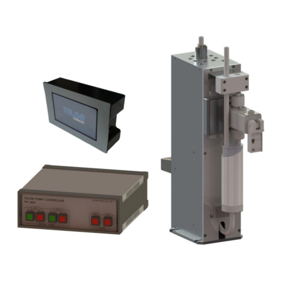
- Page 1 TP-50BS (Rev 1.0) Pump for PR Dispense High Viscosity Pump MODEL : TP-50BS TALON TECH CO. LTD. TALON TECH CO. LTD.
-
Page 2: Table Of Contents
TP-50BS (Rev 1.0) CONTENTS 1. System Configurations……………………………….…………………………………………………………………………………………. 2. System Specifications……………………………………………………………………………………………………………………………. 2-1. Pump [TP-50BS]…….…………………………………………………………………………………………………………………………. 2-2. Controller [TPC-5002].………..……………………………………………………………………………………………………………. 2-3. Touch Pad [TTP-5016]………………………………………………………………………………………………………………………. 3. System In/Exterior Names…….………………………….………………………………………………………………………………….. 3-1. Pump Exterior Names…………………………………………………………………………………………….………………………… 3-1-1. Pump Name Explanation……………………………………………………………………………………….…………………. 3-2. Controller Exterior Names..…………………………………………………………………………………………………………..… 3-2-1. Controller Name Explanation..……..…………………………………………………………………………………………... - Page 3 6-6-3. Recipe Setting………………………………………………………………………………………………….………………………... 6-7. Notice on Pump Operation.………….………………………………………………………………………………………….……… 7. Maintenance……………………………………………...…………………………………………………………………………………………… 7-1. Manual Purge Method……….……………………………………………………………………………………………………………. 7-2. Suck-Back Setting………….…………………………………………………………………………………………………………………. 8. Recommended Spares/Mechanical Dimensions…………..…………………………………………………………………….. 8-1. TP-50BS Spare Parts…………………………..…………………………………………………………………………………………….. 8-2. Pump Dimensions………………….………………………………………………………………………………………………………… 8-2-1. Front/Rear View……………………………………………………………………………………………….………………………... 8-2-2. Side View………...………….……………………………………………………………………………………………………………... 8-3. Controller Dimensions……..…………………………………………………………………………………….………………………... 8-3-1. Front View………………………….…………………………………………………………………………….………………………...
-
Page 4: System Configurations
Max 16ea Pump Control TP-50BS pump can be used as the above configuration and has been developed for the semiconductor system’s automation by operating RS422 communication. Especially, the adoption of servo motor is good for the high degree of PR dispense. The basic communication between the touch pad and the pump is RS422 Multi Drop method. -
Page 5: System Specifications
TP-50BS (Rev 1.0) System Specifications 2-1 Pump [ TP-50BS ] ITEM SPEC REMARKS Dispense Volume Range 1.0cp ~ 7cc Dispense Volume Resolution ±0.01cc Dispense / Reload Rate 0.3cc/sec ~ 1.2cc/sec Dispense Repeatability ≤±0.04 (Polyimide PIX/PIQ) Viscosity 200cp ~ 20,000cp Drive System... -
Page 6: Controller [Tpc-5002]
TP-50BS (Rev 1.0) 2-2 Controller [ TPC-5002 ] ITEM SPEC REMARKS Electric Power 85VAC ~ 264VAC, 50~60Hz Controller Power DC 24V (current consumption Max 1A) Panel Use Drive Pump No. 2 Pumps Pump Operation Mode Fixed Mode Main CPU 80c296 (16bit Processor) 1. -
Page 7: System In/Exterior Names
TP-50BS (Rev 1.0) System In/Exterior Names 3-1 Pump In/Exterior Names ① PR Out ② PR In ③ PR Drain ④ Toggle Valve ⑥ Pump Connector ⑤ Buffer Tank 3-1-1 Pump Name Explanation ① PR Out - Chemical Dispense. (⅜ Inch Teflon) ②... -
Page 8: Controller Exterior Names
TP-50BS (Rev 1.0) 3-2 Controller Exterior Names ① ② ③ ④ ⑤ ⑥ [TPC-5002 Front] ⑨ ⑩ ⑬ ⑦ ⑧ ⑭ ⑮ ⑪ ⑫ [TPC-5002 Rear] 3-2-1 Controller Name Explanation ① CH-1 In Sol S/W - After CH-1 Pump Dispense, LED Lamp Switch for Reload Operation Condition. - Page 9 TP-50BS (Rev 1.0) ⑥ CH-2 Power S/W - CH-2 Power On / Off Switch. ⑦ Controller Main S/W - Main Power Switch for controller. ⑧ Main AC-IN - AC100~220V (50 / 60Hz) Power Connector. ⑨ CH-1 Pump Connector - CH-1 Pump Connector. (D-SUB 15P Female) ⑩...
-
Page 10: Touch Pad Exterior Names
TP-50BS (Rev 1.0) 3-3 Touch Pad Exterior Names ① Touch Panel ② Power Source (DC12~24V) ④ Com Port (RS422) ③ Com Port (RS422) 3-3-1 Touch Pad Name Explanation ① Touch Panel - Touching area ② Power In - Touch Pad Power DC12~24V Connector. -
Page 11: Track/Auxiliary Interface
TP-50BS (Rev 1.0) Track / Auxiliary Interface 4-1 Track Interface Signal Recipe Select START Active Recipe High High High High High High High [Recipe Select Table] It is Timing Chart. On Ready condition, when Start Signal becomes active, each signal is same as the chart. -
Page 12: Track Interface Wiring
TP-50BS (Rev 1.0) 4-2 Track Interface Wiring Controller Side Track Side <Stop / Warning Active High> <End / Home Active Low> <Start1, 2, 3 Active Low> - 9 - TALON TECH CO. LTD. -
Page 13: Cable Pin Assign
TP-50BS (Rev 1.0) 4-3 Cable Pin Assign Pump Cable(D-SUB 15P) Number Controller Pump 1 : 1 PUMP_CW 1 : 1 PUMP_CCW 1 : 1 +24V 1 : 1 E_HOME_SIGNAL 1 : 1 E_END_SIGNAL 1 : 1 E_MOTOR_ALARM 1 : 1... - Page 14 TP-50BS (Rev 1.0) Track Cable(D-SUB 15P) Encompass Type Connecting Way Number Controller Track (ACT-12) Horose 20P Not Use Not Use Not Use Pump I/O Board Not Use ↓ START 1 Pump I/O CONN Board START 2 ↓ OUT SOL V/V 6 =>...
-
Page 15: External Cable Length
TP-50BS (Rev 1.0) External Cable Length 5-1 Pump Cable 5-2 Track Cable Standard N2 Type Encompass Type - 12 - TALON TECH CO. LTD. -
Page 16: Touch Pad Cable
TP-50BS (Rev 1.0) 5-3 Touch Pad Cable - 13 - TALON TECH CO. LTD. -
Page 17: Touch Pad Operation
TP-50BS (Rev 1.0) Touch Pad Operation 6-1 Operation 6-1-1 Initial Screen The pumps’ ID, which are cable-connected to touch pad, are auto-searched every 20 sec. On every lower menu, if there isn’t any input for 1 min, the initial screen is back. The pump, which is not searched, cannot be chosen. -
Page 18: Dispense
TP-50BS (Rev 1.0) 6-1-4 Dispense On executing Start Run, Run Recipe runs one time dispense. In case of Start Cycle, Cycle Recipe (4th Recipe) works as many as set counts. 6-1-5 Recipe Setting For Recipe Setting, touch # under No. and input recipe # that you want to go in and touch ‘Ent’. At this time, Recipe Data is automatically shown on the screen. -
Page 19: Configuration Of Pump
Stop Error Setting. [Discuss with Talon Tech] 6-1-6-1 ID Setting ID changes without any discussion could make the controller error. It is much better to ask Talon Tech. 6-1-6-2 Maint Mode, Run Mode, Pump Reset Setting Main Mode is to show the message of pump operation on the text window. Run Mode only shows as data code. -
Page 20: Example
TP-50BS (Rev 1.0) Calibration – Per each Recipe, it is possible to set the calibration value. If there is the differences between the real value and the setting value, set the calibration value higher or lower % at the standard- 100. -
Page 21: Recipe Setting
TP-50BS (Rev 1.0) 6-2-2 Recipe Setting Choose the recipe # and touch ‘Ent’ button. The chosen recipe data is automatically read from the pump. Set the recipe’s volume & time and touch ‘Set’ button. - 18 - TALON TECH CO. LTD. -
Page 22: Cycle Purge Method
TP-50BS (Rev 1.0) 6-3 Cycle Purge Method 1. Choose the pump nozzle for the cycle purge. - Pump condition is same as Ready of [PIC 1]. * On Busy condition, Cycle Start cannot be done on the screen. [PIC 1] 2. - Page 23 TP-50BS (Rev 1.0) 6. Input Recipe Data to be changed. - Count means Dispense #. - In case of Count #10 and Start Cycle on Dispense menu, Recipe #4 executes 10 times of Dispense. - Reload Volume inputs same as Disp. Volume automatically.
-
Page 24: Reset On Pump Error
TP-50BS (Rev 1.0) 6-4 Reset on Pump Error 1. Choose the alarmed pump. Check the errored pump before Pump Reset. When the alarm occurs on the pump, you can check the alarm Thru the alarm LED beside Sub Panel and check the nozzle on the system’s Panel. -
Page 25: Touch Pad Menu Tree
TP-50BS (Rev 1.0) 6-5 Touch Pad Menu Tree 6-6 Notice 6-6-1 Dispense Cycle During the system or the manual dispense, the pump doesn’t save Recipe changes and setting changes. At this time, ‘Busy’ window is shown normally. 6-6-2 Pump ID Setting The basic ID is ‘11’. -
Page 26: Notice On Pump Operation
TP-50BS (Rev 1.0) 6-7 Notice on Pump Operation 1. During Pump is under process (RUN OR CYCLE) don’t try to modify the data. (Please do it after Pump had stop properly) ▶ In this term of “modify data” means changing recipe, cycle, CAL value etc. If you modified the data during pump operation, BUSY screen will be pop-up and it will be not saved. -
Page 27: Maintenance
TP-50BS (Rev 1.0) Maintenance 7-1 Manual Purge Method N2 Press [PIC 1] ① ② [PIC 2] In order to purge, press N2 into PR bottle as per [PIC 1] and push ② (OUT SOL) Button of Manual Purge S/W as per [PIC 2] to open Suck Back Valve. -
Page 28: Suck-Back Setting
TP-50BS (Rev 1.0) 7-2 Suck-Back Setting ③ Suck-Back Volume (Adjust Suck-Back) ③-① Lock Nut ② Cut Off (PR Cut Timing) ②-① Lock Nut ④ Suck-Back Speed (Adjust Suck-Back speed) ④-① Lock Nut Main Air Inlet ① Main Air (Adjust overall Air volume) ①-①... - Page 29 TP-50BS (Rev 1.0) 8. Fasten every knob’s lock nut. (①-①, ②-①, ③-①, ④-①) 9. Dispense resist again to final check. 10. If value is not correct, go back to order NO.3. REFERENCES FOR WORKING SEQUENCE ②, ③ ① ④...
-
Page 30: Recommended Spares/Mechanical Dimensions
TP-50BS (Rev 1.0) Recommended Spares / Mechanical Dimensions 8-1 TP-50BS Spare Parts Division Part NO. Description TL-50BS-TA-001 Buffer Tank Ass’y TL-50BS-MA-001 Ball Screw TL-50BS-MA-002 Coupling TL-50BS-MA-003 LM Guide TL-50BS-MA-004 Support Unit Pump TL-50BS-EA-001 Sensor TL-50BS-EB-004 Motor TL-50BS-ET-001 O-Ring TL-50BS-CA-005 Toggle Valve... -
Page 31: Pump Dimensions
TP-50BS (Rev 1.0) 8-2 Pump Dimensions 8-2-1 Front/Rear View [ Front View ] [ Rear View ] 8-2-2 Side View [ Side View ] - 28 - TALON TECH CO. LTD. -
Page 32: Controller Dimensions
TP-50BS (Rev 1.0) 8-3 Controller Dimensions 8-3-1 Front View 8-3-2 Rear View 8-3-3 Side View - 29 - TALON TECH CO. LTD. -
Page 33: Touch Pad Dimensions
TP-50BS (Rev 1.0) 8-4 Touch Pad Dimensions 8-4-1 Front View 8-4-2 Rear View 8-4-3 Side View - 30 - TALON TECH CO. LTD. -
Page 34: Installation Method
TP-50BS (Rev 1.0) 8-5 Installation Method 8-5-1 Pump Installation Sequence 1. Prepare the space for the pump installation. 2. As per the below picture, tighten the panel base plate with 4 pieces of M3 screw. Make 2.6mm hole and Tap M3 8-5-2 Piping Method 1. -
Page 35: Touch Pad Installation Method
TP-50BS (Rev 1.0) 8-5-3 Touch Pad Installation Method Back Cover [PIC 1] Equipment-side Panel Touch Pad [PIC 2] [PIC 3] 1. As per [PIC 1], peel the sticker a little until the screw is seen. And loose the screw to take the back cover apart. -
Page 36: Suggested Recipe Setting Value
TP-50BS (Rev 1.0) 8-5-4 Suggested Recipe Setting Value (PR viscosity: 1,800cP) Volume(g) Data Input Dispense/Time Data Input Reload/Time Data Input 2100 21.5 2150 2200 22.5 2250 2300 23.5 2350 2400 Suggested setting value as per time Dispense time(D/T) formula : Volume(g)+1.5=D/T => ex) 5+1.5=6.5 Reload time formula : Volume(g)+16=R/T =>...
Need help?
Do you have a question about the TP-50BS and is the answer not in the manual?
Questions and answers