
Related Manuals for Talon TP-40BA


Summary of Contents for Talon TP-40BA
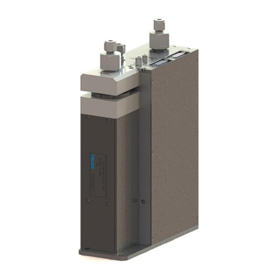
- Page 1 TP-40BA (Rev 1.0) Excellent Dispense Volume Reliability Pump & Controller – Built-in type MODEL : TP-40BA TALON TECH CO. LTD. TALON TECH CO. LTD.
-
Page 2: Table Of Contents
TP-40BA (Rev 1.0) CONTENTS 1. System Configurations…………………………………………………………………………………………………………………………. 2. System Specifications……………………………………………………………………………………………………………………………. 2-1. Pump [TP-40BA]…….…………………………………………………………………………………………………………………………. 2-2. Control Board………..…………………………………………………………………………………………………………………………. 2-3. Touch pad…………………………………………………………………………………………………………………………………………. 3. System In/Exterior Names……………..…………………………………………………………………………………………………….. 3-1. Pump In/Exterior Names...………………………………………………………………………………………….…………………… 3-1-1. Pump Name Explanation..…………………………………………………………………………………….…………………. 3-2. Touch Pad Exterior Names..…………………………………………………………………………………………………………….. 3-2-1. Touch Pad Name Explanation…………………………………………………………………………………………………... - Page 3 8-1-1. Degas Pump Cover Dis/Assembly….…..…………………………………………………………………………………….. 8-1-2. Buffer Tank Empty Sensor’s Sensitivity Adjustment……...…………………………………………………………. 8-1-3. Driving Shaft Condition Check & Grease up on Ball Screw………...………..………………………………… 9. Recommended Spares/Mechanical Dimensions………………………………………………………………………………… 9-1. TP-40BA Spare Parts………………………………………………………………………….…………………………………………….. 9-2. Pump Dimensions……………………………………………………………………………………………………………………………. 9-2-1. Front View……………………………………………………………………………………………………………………………….… 9-2-2. Side View……………………………………………………………………………………………………………………………………...
-
Page 4: System Configurations
Pump Control (Max 8ea Ch) TP-40BA pump can be used as the above configuration and has been developed for the semiconductor system’s automation by operating RS422 communication. Especially, the adoption of servo motor is good for the high degree of PR dispense. The basic communication between the touch pad and the pump is RS422 Multi Drop method. -
Page 5: System Specifications
TP-40BA (Rev 1.0) System Specifications 2-1 Pump [TP-40BA] ITEM SPEC REMARKS Dispense Volume Range 0.5cc ~ 7.0cc Suck-Back Volume Range 0.0cc ~ 3.5cc Dispense / Reload Rate 0.1cc/sec ~ 7.0cc/sec Suck-Back Rate 0.1cc/sec ~ 7.0cc/sec Dispense Volume Resolution 0.0025cc Dispense Repeatability ≤±0.02(2.2cp, 23℃) -
Page 6: Control Board
TP-40BA (Rev 1.0) 2-2 Control Board ITEM SPEC REMARKS Power Source DC 24V (current consumption : 1A) Drive Pump No. 1 Pumps Pump Operation Mode Fixed Mode Main CPU 80c296 (16bit Processor) 1. Pump Driving Signal From Track M/C-Pump Input Signal Start Signal(3ea) 1. -
Page 7: System In/Exterior Names
TP-40BA (Rev 1.0) System In/Exterior Names 3-1 Pump In/Exterior Names ① Cylinder ② Main Control Board ③ Air Sol Block Ass’y ④ Buffer Tank ⑤ Degas Pump ⑥ Dispense Pump - 4 - TALON TECH CO. LTD. -
Page 8: Pump Name Explanation
TP-40BA (Rev 1.0) ⑦ Vent ⑫ Track ⑧ Empty ⑬ COM ⑨ S/Back ⑩ PR In ⑭ Air In ⑪ PR Out 3-1-1 Pump Name Explanation ① Cylinder - Function of containing PR and dispensed by bellows ② Main Control Board - Main Control Board for all pump controls ③... -
Page 9: Touch Pad Exterior Names
TP-40BA (Rev 1.0) - Chemical Supply. (¼ Inch Teflon) ⑪ PR Out - Chemical Dispense. (¼ Inch Teflon) ⑫ Track - Track cable connector from pump to machine. (D-SUB Male 15P) ⑬ COM - Communication Cable Connector from pump to touch pad. (D-SUB Male 15P) ⑭... -
Page 10: Touch Pad Connection Board Exterior Names
TP-40BA (Rev 1.0) 3-3 Touch Pad Connection Board Exterior Names ② Main COM ① Touch Pad ③ Switching I/O ④ RS422 comm. (J1 ~ J8) [Main COM Circuit] [Switching I/O Circuit] 3-3-1 Touch Pad Connection Board Name Explanation ① Touch Pad - Touch Pad Communication Connector. -
Page 11: Wiring & Signal Interface
TP-40BA (Rev 1.0) Wiring & Signal Interface 4-1 Track I/O Signal Timing Chart. - 8 - TALON TECH CO. LTD. -
Page 12: Track Pin Assign
TP-40BA (Rev 1.0) 4-2 Track Pin Assign Track Pin Assign [Male Type D-SUB 15P] Pin NO. Signal Name Description + 24VDC Input Machine -> Pump Supply Power + 24VDC Input Machine -> Pump Supply Power Input Machine -> Pump Supply Power Input Machine ->... -
Page 13: Touch Pad Pin Assign
TP-40BA (Rev 1.0) 4-4 Touch Pad Pin Assign Touch Pad RS422 Pin Assign [Male Type D-SUB 9P] Pin NO. Signal Name Description Output CONN Board Supply Power Not Use Not Use Not Use Not Use Input RS422 Receive + (Pump side) -
Page 14: Dispense Trigger Select
TP-40BA (Rev 1.0) 4-5 Dispense Trigger Select “0” Trigger Off “1” Trigger On Recipe Start1 Start2 Start3 Remark Select Cycle Recipe - 11 - TALON TECH CO. LTD. -
Page 15: External Cable Length
TP-40BA (Rev 1.0) External Cable Length 5-1 Track Cable 5-2 COM Cable 5-3 Touch Pad Cable Cable for Touch Pad in Use Cable for Touch Pad in no Use Touch Pad Power Cable Touch Pad Main COM Cable Touch Pad Switching I/O Cable - 12 - TALON TECH CO. -
Page 16: Touch Pad Operation
TP-40BA (Rev 1.0) Touch Pad Operation 6-1 Operation 6-1-1 Initial Screen The pumps’ ID, which are cable-connected to touch pad, are auto-searched every 20 sec. On every lower menu, if there isn’t any input for 1 min, the initial screen is back. The pump, which is not searched, cannot be chosen. -
Page 17: Dispense
TP-40BA (Rev 1.0) 6-1-4 Dispense On executing Start Run, Run Recipe runs one time dispense. In case of Start Cycle, Cycle Recipe (4th Recipe) works as many as set counts. 6-1-5 Recipe For Recipe Setting, touch # under No. and input recipe # that you want to go in and touch ‘Ent’. At this time, Recipe Data is automatically shown on the screen. -
Page 18: Degas
TP-40BA (Rev 1.0) 6-1-6 Degas Degas Count means to set the degas counts after the empty sensor senses the buffer tank’s empty. When the set counts are over, warning or stop alarm occurs depending on ‘Error Mask Setting’. ‘Using Empty Sensor’ is about the empty sensor’s setting. So, it becomes ‘Yes’ on normal situation. - Page 19 TP-40BA (Rev 1.0) Vital Check pump’s response and in case of response, ‘vital’ window activates and disappears right away. At the left window, the response data is shown. Error Status Shown Error Code Data. Set ID Change Pump ID. [Discuss with Talon Tech] Maint Mode Change Pump Mode to Maint.
- Page 20 TP-40BA (Rev 1.0) If there is no response from the pump, the window keeps showing. If there is already the same pump ID, the window – ‘Conflict’ shows and push ‘OK’ and reset. ▶ Maint Mode, Run Mode, Pump Reset Setting Main Mode is to show the message of pump work on the text window.
-
Page 21: Calibration
TP-40BA (Rev 1.0) 6-1-8 Calibration Calibration - Per each Recipe, it is possible to set the calibration value. If there is the differences between the real value and the setting value, set the calibration value higher or lower % at the standard- 100. -
Page 22: Recipe
TP-40BA (Rev 1.0) Stop Cycle only works the case of using Start Cycle. Keep touching Stop Cycle button. 6-2-2 Recipe Choose the recipe # and touch ‘Ent’ button. The chosen recipe data is automatically read from the pump. Set the recipe’s volume & time and touch ‘Set’ button. -
Page 23: Id Setting
TP-40BA (Rev 1.0) 6-2-3 ID Setting Choose ID # which you want to change from 11~44. ID consists of 2 digits. The 2 digit means Coater# and the 1 digit means Nozzle#. Total 16 ID setting is possible. - 20 -... - Page 24 TP-40BA (Rev 1.0) After inputting ID & touch ‘Set ID’, input the password and enter. After exchanging for new ID, the pump is automatically initialized. - 21 - TALON TECH CO. LTD.
-
Page 25: Reset On Pump Error
TP-40BA (Rev 1.0) 6-2-4 Reset on Pump Error 1. Choose the alarmed pump. Check the errored pump before Pump Reset. When the alarm occurs on the pump, you can check the alarm Thru the alarm LED beside Sub Panel and check the nozzle on the system’s Panel. -
Page 26: Touch Pad Menu Tree
TP-40BA (Rev 1.0) 6-3 Touch Pad Menu Tree - 23 - TALON TECH CO. LTD. -
Page 27: Notice
TP-40BA (Rev 1.0) 6-4 Notice 6-4-1 Degas Function Degas Overtime : Degas Pump’s Overtime counts. If the real pumping is more than the Degas setting count and the empty sensor still senses as empty, the error occurs. At this time, you set the overtime counts. -
Page 28: Pump Operation Sequence
TP-40BA (Rev 1.0) Pump Operation Sequence TP-40BA Pump Operation Sequence consists of Degas Pump and Dispense Pump. 7-1 Degas Pump 7-1-1 Degas Pump Role Degas Pump has two functions roughly. 1. Take away bubbles made by PR before dispense. When PR fills up in the buffer tank, bubbles go up and PR goes down. So, PR can be dispensed without bubbles through the buffer tank (bubble trap). -
Page 29: Degas Pump Operation Sequence
TP-40BA (Rev 1.0) 7-1-2 Degas Pump Operation Sequence 1. Buffer Empty If PR doesn’t fills up at the level of the empty sensor, the empty sensor sends the empty signal to the controller. 2. Degas Sol V/V Operation When the empty signal inputs, the controller makes the degas sol work. The air supplies to the degas pump and the retracted bellows pulls up PR from the PR bottle. -
Page 30: Dispense Pump
TP-40BA (Rev 1.0) 7-2 Dispense Pump 6-2-1 Dispense Pump’s Role Dispense Pump function is to dispense PR within the set time and with the accuracy. 1. Dispense Pump Configuration Dispense Pump consists of the driving motor, driver, bellows, position sensors, etc. - Page 31 TP-40BA (Rev 1.0) 2. Suck-Back After Dispense finish, the suck back valve is open upto the set time in order to reload. At this time, PR is suck-backed at the tip of nozzle. 3. Reload After Suck-Back finish, during suck-back V/V close, the reload proceeds up to home sensor.
-
Page 32: Maintenance
TP-40BA (Rev 1.0) Maintenance 8-1 Pump Parts Dis/Assembly 8-1-1 Degas Pump Cover Dis/Assembly 1. As per the below [PIC 1], use 2mm wrench to release Pump Cover Mounting M2.5 Screw(6ea) to open the cover. 2. The assembly is the reverse order of the disassembly. -
Page 33: Driving Shaft Condition Check & Grease Up On Ball Screw
TP-40BA (Rev 1.0) Sensitivity adjustment Hole [PIC 2] 8-1-3 Driving Shaft Condition Check & Grease up on Ball Screw 1. As per the below [PIC 3], use 2mm wrench to release Pump Cover Mounting M2.5 Screw(4ea), Screw to open the cover. -
Page 34: Recommended Spares/Mechanical Dimensions
TP-40BA (Rev 1.0) Recommended Spares / Mechanical Dimensions 9-1 TP-40BA Spare Parts Division Part NO. Description TL-40BA-TA-001 Outer Type Bellows TL-40BA-TA-002 Body TL-40BA-TA-003 Check Valve Ass’y TL-40BA-TA-004 Cylinder TL-40BA-TA-005 Union Nut TL-40BA-TA-006 ¼” Ferrule TL-40BA-TA-007 ¼” Back Ferrule TL-40BA-MA-001 Ball Screw... -
Page 35: Pump Dimensions
TP-40BA (Rev 1.0) 9-2 Pump Dimensions 9-2-1 Front View 9-2-2 Side View - 32 - TALON TECH CO. LTD. -
Page 36: Touch Pad Dimensions
TP-40BA (Rev 1.0) 9-3 Touch Pad Dimensions 9-3-1 Front View 9-3-2 Rear View 9-3-3 Side View - 33 - TALON TECH CO. LTD. -
Page 37: Touch Pad Connection Board Dimensions
TP-40BA (Rev 1.0) 9-4 Touch Pad Connection Board Dimensions 9-4-1 Top View - 34 - TALON TECH CO. LTD. -
Page 38: Installation Method
TP-40BA (Rev 1.0) 9-5 Installation Method 9-5-1 Pump Installation Sequence 1. Set aside the space for the pump installation. 2. As per the below picture, tighten the panel base plate with 2 pieces of M4 screw. Make 3.25 mm hole and tap M4 9-5-2 Piping Method 1. -
Page 39: Touch Pad Installation Method
TP-40BA (Rev 1.0) 9-5-3 Touch Pad Installation Method Back Cover [PIC 1] Equipment-side Panel Touch Pad [PIC 2] [PIC 3] 1. As per [PIC 1], peel the sticker a little until the screw is seen. And loose the screw to take the back cover apart. -
Page 40: Touch Pad Connection Board Bracket Installation Method
TP-40BA (Rev 1.0) 9-5-4 Touch Pad Connection Board Bracket Installation Method Touch Pad Connection Board Hole M3 X 4ea [PIC 1] [INSTALLATION SUGGESTION 1] [PIC 2] [INSTALLATION SUGGESTION 2] 1. Refer to [PIC 1] / [PIC 2]. Install the bracket on the panel on the equipment.
Need help?
Do you have a question about the TP-40BA and is the answer not in the manual?
Questions and answers