
Related Manuals for Megger HV DAC-200


Summary of Contents for Megger HV DAC-200
- Page 1 HV DAC-200 Partial discharge measuring system USER GUIDE Issue: C (04/2022) - EN Article number: 86616...
-
Page 3: Consultation With Megger
The information in this document is subject to change without notice and should not be construed as a commitment by Megger. Megger cannot be made liable for technical or printing errors or shortcomings of this handbook. Megger also disclaims all responsibility for damage resulting... -
Page 4: Terms Of Warranty
Each component and product replaced in accordance with this warranty becomes the property of Megger. All warranty claims versus Megger are hereby limited to a period of 12 months from the date of delivery. Each component supplied by Megger within the context of warranty will also be covered by this warranty for the remaining period of time but for 90 days at least. -
Page 5: Table Of Contents
Contents Contents Consultation with Megger ....................3 Terms of Warranty ......................4 Contents ........................... 5 Safety Instructions ................... 7 General Notes ....................7 General Safety Instructions and Warnings ............8 Technical Description ..................9 Abbreviations ...................... 9 System Description ..................10 Technical Data .................... - Page 6 Contents 5.3.4.2 Typical Procedure for Monitored Withstand Testing ........75 5.3.5 Stopping / Finishing a Measurement ..............76 Evaluating Measurement Results and Creating a Report ......77 Manual Evaluation of Partial Discharges ............80 6.1.1 Determining Possible Sources of PD Faults ............ 80 6.1.2 Analysing Individual PD Events ...............
-
Page 7: Safety Instructions
It is important to observe the generally applicable electrical regulations of the country in Working with products which the device will be installed and operated, as well as the current national accident from Megger prevention regulations and internal company directives (work, operating and safety regulations). -
Page 8: General Safety Instructions And Warnings
If, contrary to the regulations, any other extinguishing agent is • used for fire fighting, this may lead to damage at the electrical installation. Megger disclaims any liability for consequential damage. Furthermore, when using a powder extinguisher near high-voltage installations, there is a danger that the operator of the fire extinguisher will get an electrical shock from a voltage arc-over (due to the powder dust created). -
Page 9: Technical Description
Technical Description Technical Description Abbreviations In this manual the following abbreviations are used: Partial Discharge Damped AC PDIV Partial Discharge Inception Voltage PDEV Partial Discharge Extinction Voltage Time Domain Reflectometry (or Time Domain Reflectometer) Voltage Withstand Diagnosis Ankoppelvierpol (Quadripole) Monitored Withstand Test... -
Page 10: System Description
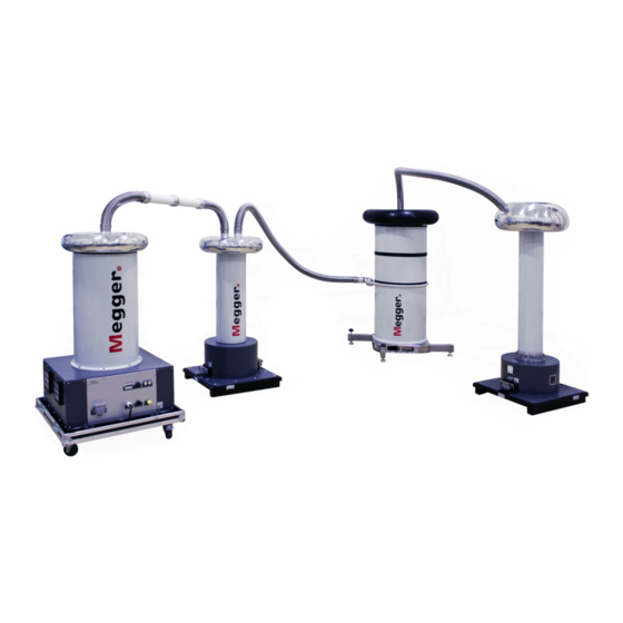
Technical Description System Description The HV DAC-200 is a partial discharge measurement system that allows for the Functional description identification, classification and location of PD faults in the insulation and the accessories of all kinds of high voltage cables. It essentially consists of a DC voltage source, a travelling wave resistor, a switch, an inductor and a coupling unit with integrated measuring impedance and PD detector. - Page 11 • internal noise level for voltages >>180 kV) Intuitive control and analysis software, suitable for the universal use with • different systems of Megger • Quick and fully automatic calibration in one step • PD mapping and statistical evaluation in real time Fully automatic report generation directly after a measurement possible •...
- Page 12 Technical Description Scope of delivery The transport boxes include the following transport boxes: QTY Box label Box content Article number “Source” HV source 2007401 “Switch” Thyristor switch 2007402 (with content) 90019028 (empty) “Inductor/Top” HV Inductor 2005395 (with content) 90007045 (empty) “Inductor/Bottom”...
- Page 13 Technical Description QTY Accessory Description Article number Earth lead for inductor Length: 2005880 support feet Cross section: 10 mm Color: green/yellow Earth lead Length: 2005334 2005335 10 m 2005336 Color: black Cross section: 25 mm Plug type: MC10 Flat ribbon earth cable Length: 15 m 90015481...
- Page 14 Technical Description The box labeled with “Accessory Box 2” contains the following accessories: QTY Accessory Description Article number Base plate of inductor 2006314 support feet Arms of inductor support 2006680 feet HV connection tube Connects the coupling unit to the 2006458 cable under test Length:...
-
Page 15: Technical Data
Technical Description Technical Data The HV DAC-200 system is specified by the following parameters: Technical parameters Parameter Value Output voltage 25 kV … 200 kV DC (diagnosis only up to 180 kV) DAC frequency 20 Hz … 300 Hz Testable load capacitance 35 nF …... - Page 16 Technical Description The following diagram illustrates the dependence of the maximum permissible test voltage Height-dependent on the operating altitude and the operating temperature: maximum voltage Operating height [m]...
- Page 17 Technical Description Weight and dimensions The individual main components of the HV DAC-200 have the following weight and dimensions: Component Data Dimensions 840 x 1465 x 980 mm (W x H x D) Weight 110 kg “Source” Dimensions 700 x 1417 x 700 mm...
- Page 18 Technical Description Component Data Dimensions 700 x 1765 x 700 mm (W x H x D) Weight 123 kg “Coupler” Dimensions 700 x 1700 x 700 mm (W x H x D) Weight 115 kg “Support Capacitor” (optional)
-
Page 19: Connections, Controls And Indicators
Technical Description Connections, Controls and Indicators The following connection and control elements are located on the base of the HV source: HV source Element Description Socket for connection to the external safety device Socket for connection to the external safety device with operating function and to the notebook Connection point for ribbon earthing cable Connector for connection to the switch... - Page 20 Technical Description The external safety devices have the following controls and indicators: External safety device Part Description Green signal light Lights up when the system is switched on but is not in high voltage operation. “HV interlock” key switch High voltage unlocked High voltage locked In the locked state, the key can be removed and the system can thus be protected against unauthorised high-voltage operation.
- Page 21 Technical Description Coupling unit The following connectors and indicators are located on the base of the coupling unit: Element Description Status LEDs indicating the following states of the PD detector: Left LED Right LED Green Measurement underway Software and PD detector connected Orange Measurement stopped and...
-
Page 22: Technical Background
Technical Background To be informed about the condition and residual life of their resources is increasingly What is Partial important for network operators in order to be able to plan and optimise the investment Discharge and why test and maintenance measures. for it? By the use of condition-based maintenance of medium and high voltage cable networks with the help of cable diagnosis and cable tests, it is possible to considerably reduce the... - Page 23 In order to measure partial discharges, the test object is applied with the required voltage. How can PD be The generated high-frequency PD signals are decoupled by means of a special AKV. measured and located? By gradually raising the voltage it is possible to detect at which voltage the PD ignites (PDIV) and how the PD level changes with increasing voltage.
-
Page 24: Commissioning
Commissioning Commissioning General safety instructions for set-up and commissioning The guidelines for implementation of occupational safety when operating a test system / test van often differ between one network operator and another and it is not uncommon for national regulations (like, i.e. the WARNING German BGI 5191) to be used as well. - Page 25 Commissioning The following picture shows the simplified connection diagram: Connection diagram 400 V Prohibition zone and test area acc. to DIN EN 50191 (VDE 0104) The system components itself and the unshielded connection cables are to be considered as live parts during the whole measurement. Dimensioning of prohibition zone and test area is to be carried out in accordance to DIN EN 50191 (VDE 0104).
- Page 26 Commissioning The following minimum distances between the system components must be observed Minimum distances when setting up the HV DAC-200: between system components ≥1.20 m ≥1.20 m ≥1.20 m ≥1.50 m „Source“ „Switch“ „Inductor“ „Coupler“ “Test object” ≥1.00 m ≥1.00 m ≥1.00 m...
-
Page 27: Setting Up The Coupling Unit
Commissioning 3.1.1 Setting Up the Coupling Unit Proceed as follows to set up the coupling unit: Step Action Position and align the transport box labelled with “Coupler” next to the cable under test as shown in the figure below and fix the two wheels which are facing the cable under test: ≥1.5 m Use the available handles to raise the transport box to upright position as... - Page 28 Commissioning Step Action Carefully remove the lid (side without wheels) of the transport box and unfasten the tension belt fixing the coupling unit. Remove the lower part of the transport box. Do not remove the short-circuit adapter from the coupling unit yet! Remove any dust and other debris from the isolator pipe.
- Page 29 Commissioning Step Action Take a black earth lead of appropriate length out of “Accessory box 2” and use it to connect the MC 10 connector at the base of the coupling unit with the screen of the cable under test (operational earth). The plug connection at the base of the coupling unit is secured by a snap-on locking system.
-
Page 30: Setting Up The Support Capacitor (Optional)
Commissioning 3.1.2 Setting Up the Support Capacitor (optional) Proceed as follows to install the optional support capacitor which is only required in case of very low load capacity: Step Action Position and align the transport box labelled with “Support Capacitor” next to the coupling unit as shown in the figure below and fix the two wheels which are facing the coupling unit: 1.2 m …... - Page 31 Commissioning Step Action Carefully remove the lid (side without wheels) of the transport box and unfasten the tension belt fixing the support capacitor. Remove the lower part of the transport box. Do not remove the short-circuit adapter from the support capacitor yet!
- Page 32 Commissioning Step Action Take the black earth lead out of the “Support Capacitor” box and use it to connect the MC 10 connector at the base of the support capacitor with the screen of the cable under test (operational earth). The plug connection at the base of the support capacitor is secured by a snap-on locking system.
-
Page 33: Setting Up The Inductor
Commissioning 3.1.3 Setting Up the Inductor Proceed as follows to set up the inductor: Step Action Position the inductor support feet on stable and level ground in a distance between 1.0 m and 1.5 m from the coupling unit or the support capacitor (if used). - Page 34 Commissioning Step Action Put the lifting device on the inductor base as shown in the figure below: Anchor the lifting device using the four attached self locking pins. Push button to release the locking If possible, connect the eye on top of the lifting device to an overhead crane. If no crane is available, at least 4 persons are required to lift the inductor base! CAUTION...
- Page 35 Commissioning Step Action Lift the inductor base and rotate it until the connector is facing away from the coupling unit. Coupling unit While putting down the inductor base on the support feet, make sure the four bolt heads sticking out of the support feet are guided through the holes in the bottom of the inductor base.
- Page 36 Commissioning Step Action By means of the lifting device (see steps 4 to 6), lift one inductor after the other from the respective transport box on the inductor base. Both the sequence and the alignment are defined by colored stickers on the inductors. If no crane is available, at least 4 persons are required to lift one inductor! CAUTION...
- Page 37 Commissioning Step Action Place the electrode on the inductor and make sure the two red triangles are aligned with one another. Lock the locking mechanism (see step 11) and tighten the two locking screws. Remove the protective sleeve from the electrode.
-
Page 38: Setting Up The Switch
Commissioning 3.1.4 Setting Up the Switch Proceed as follows to set up the switch: Step Action Position and align the transport box labelled with “Switch” next to the inductor as shown in the figure below and fix the two wheels which are facing the inductor: 1.0 m …... - Page 39 Commissioning Step Action Carefully remove the lid (side without wheels) of the transport box and unfasten the tension belt fixing the switch. Remove the lower part of the transport box. Remove the protective sleeve from the field control electrode. Check whether one of the silica gel desiccators on top of the switch needs to be replaced.
- Page 40 Commissioning Step Action Take the hybrid cable with the blue markings on both ends out of “Accessory Box 1” and use it to make a connection between the switch and the coupling unit. The respective receptacles on the switch and coupling unit are also marked with blue stickers.
-
Page 41: Making The Hv Connections Between The Individual Components
Commissioning 3.1.5 Making the HV Connections between the individual components Proceed as follows to make the connection: Step Action Take one of the two corrugated hoses out of “Accessory box 2” and plug either of both ends into the lateral opening of the coupler’s field control electrode. Push it all the way to the stop. - Page 42 Commissioning Step Action Take the corrugated hose out of the “Support Capacitor” box and plug either of both ends into the vacant socket on top of the support capacitor. Push it all the way to the stop. Plug the other end into the socket on top of the inductor and push it all the way to the stop.
-
Page 43: Setting Up The Hv Source
Commissioning Step Action Plug the other end into the nearest of the two sockets on top of the switch and push it all the way to the stop. Make sure the clearance between the two hoses is at any point at least 1.2 m! For the remaining duration of the assembly, attach an earthing stick (not part of the scope of delivery) to the hose as shown in the figure below:... - Page 44 Commissioning Step Action Carefully remove the lid (side without wheels) of the transport box and unfasten the tension belts fixing the HV source. Remove the lower part of the transport box. Remove the protective sheath from the field control electrode. Take the 10 m copper earth lead out of “Accessory Box 1”...
- Page 45 Commissioning Step Action Take the hybrid cable with the red markings on both ends out of “Accessory Box 1” and use it to make a connection between the switch and the HV source. The respective receptacles on the HV source and the switch are also marked with red stickers.
- Page 46 Commissioning Step Action Use the AC power cord and the supplied extension cable to connect the source to a three-phase power (400 V). By default the extension cable is equipped with a 32 A / 400 V CEE plug (3P+N+E) which can be replaced by a suitable country-specific plug. Replacement has to be carried out by a qualified person.
-
Page 47: Connecting The Coupling Unit To The Cable Under Test
Commissioning 3.1.7 Connecting the Coupling Unit to the Cable Under Test Proceed as follows to make the connection: Step Action Attach the adapter with the most suitable diameter on the conductor to be tested. Tighten all screws (3 or 6, respectively - depending on the type of adapter) in order to secure the adapter on the conductor. - Page 48 Commissioning Step Action Place the torus on the adapter and make sure they are concentrically aligned. Lock the locking mechanism (see step 3) and tighten the three locking screws. The torus should now be firmly attached to the cable under test which has to be verified in a suitable manner.
- Page 49 Commissioning Step Action Slide the locking fork into the corresponding notches to lock the HV connection tube in place. Plug the other end of the HV connection tube into the opening on top of the coupler’s field control electrode and push it all the way to the stop. If HV connection tubes of different lengths are available, always use the shortest possible length possible in order to keep the interference level as low as possible.
-
Page 50: Installing The Corona Ring At The Remote End Of The Cable (Optional)
Commissioning 3.1.8 Installing the Corona Ring at the Remote End of the Cable (optional) In order to ensure the lowest possible corona discharges, the optionally available coronary ring CPT300 (see page 10) can be installed at the remote end of the cable. It is stowed away in its own box labelled with "Corona Protection Toroid"... -
Page 51: Switching On
Commissioning Switching On Please perform the following steps in order to get everything ready for the measurement: Step Action Switch on the test voltage source via the white “Mains ON” button. Remove the short-circuit adapters from the coupling / support capacitor (if used) and any earthing sticks. -
Page 52: Basic Operation Of The Software
Basic Operation of the Software Basic Operation of the Software Start Screen After the PD measurement software has been opened, the main menu appears which enables the user to call up the individual modules of the software: Main menu of the PC software Main menu of the test van software The following modules are available: Module Description... -
Page 53: Useful Features Of The Software
Basic Operation of the Software Useful Features of the Software In order to make the search in extensive lists (e.g. cable lists) easier there is always a Search and sort search form near the list in which any character string can be entered. While entering, the functions list is immediately filtered by entries that contain this character string. - Page 54 Basic Operation of the Software To guarantee quick access to frequently used cable templates, these can be added to the Administration of favourites favourites ( ) list by clicking on the symbol, or be removed from the list ( ) by clicking again.
-
Page 55: Conducting Measurements
Select the cable end at which the current measurement is conducted under Measured at. If required, select Megger HV DAC from the HV source drop down list. The drop down list is only available if more than one HV source is configured in the software. - Page 56 Conducting Measurements Step Action Click on Apply in order to confirm the selection. Before starting a new measurement task, ensure that the measurement data recording has been completed for the measurement task currently in progress! Result: The software jumps back to the start screen. The measurement task is initialised, and the cable allocated to the measurement task is displayed on top of the selection menu.
-
Page 57: Calibrating The Partial Discharge Measuring Circuit
Conducting Measurements Calibrating the Partial Discharge Measuring Circuit – In order to be able to conduct a calibration, a new measurement task must have been Prerequisites started beforehand (see page 55). Otherwise the menu point in the start screen is greyed out. -
Page 58: Conducting The Calibration
Conducting Measurements Step Action Switch the calibrator on by shortly pressing the button. With the help of the button the calibration pulse level can be adapted if required. In most cases, however, the calibration can be completed successfully with the preset calibration value of 1 nC. Cancel the earthing and short circuiting measures on both ends of the cable that is to be tested. - Page 59 Conducting Measurements Step Action Adjust the PD detector settings. Select from the dropdown menu Phase either the phase of the test object that is currently connected to the measuring system or the option All Phases. For 3-core cable systems it is generally sufficient to calibrate the circuit only once and apply the data for all phases.
- Page 60 Conducting Measurements Step Action Result: The PD detector measures the incoming pulses and tries to identify the calibration pulses the respective reflections from the far cable end. If the pulses are successfully measured, a TDR trace and a charge diagram are displayed in the left area of the window.
- Page 61 Conducting Measurements The quality of the subsequent measurement results depends on various factors, Checking the markers particularly the accuracy of calibration. It is therefore advisable to check the automatic positioning of the markers and correct them if necessary before applying the calibration data.
-
Page 62: Disconnecting The Calibrator
Conducting Measurements In the charge diagram, the line should mark roughly the average value of the periodically measured calibration pulses. If a correction has to be made, the respective mark has to be clicked once with the left mouse button. As a result, the line width of the marker increases and the mouse pointer changes into the symbol. -
Page 63: Measuring
Conducting Measurements Measuring – In order to conduct the measurement, a new measurement task must have been started Prerequisites (see page 55) beforehand and the partial discharge measuring circuit must have been calibrated (see page 57). Otherwise the menu point is greyed out in the start screen. -
Page 64: Available Diagram Types
Conducting Measurements 5.3.2 Available diagram types The measurement screen provides access to various diagrams during the measurement. Introduction In the upper part of the screen, PD mapping with the previously recorded PD events is displayed by default. The diagram type directly below can be changed using the tabs at the bottom. - Page 65 Conducting Measurements Using the Advanced menu item, you can display the advanced view filters and the pulses in the PD mapping can be filtered as you wish to provide a better overview: The following buttons are available for this purpose: Button Description Filter view according to phase.
- Page 66 Conducting Measurements In order to enlarge a certain area of the PD mapping, simply draw a frame around the area while holding the mouse button. Clicking removes the magnification. The Q(t)/U(t) view displays the temporal profile of the measured charge level (the partial Q(t)/U(t) discharge pattern) and the excitation voltage.
- Page 67 Conducting Measurements With the scrollbar, depending on the voltage waveform, you can switch back and forth between the recorded measurement windows (the individual shots for DAC, the polarity reversals for VLF-CR or the triggered PD pulses for VLF-SIN). The checkbox Switch to this view on any new event can be used to determine whether the software automatically switches to the localisation diagram with each recorded PD event.
-
Page 68: Setting The Measurement Parameters
Conducting Measurements 5.3.3 Setting the Measurement Parameters The configuration of the PD detector must be performed through the menu block specially Configuring the PD provided for this purpose: detector PD Detector Phase Q Range State Stopped The following settings are possible: Parameter Description Phase... - Page 69 Conducting Measurements The configuration of the test voltage source must be performed through the menu block Configuring the test specially provided for this purpose: voltage source Mode DAC- 5 shots 30 kV peak max kV peak kV rms x Uo Voltage 17,3 peak...
-
Page 70: Performing The Measurement
Conducting Measurements 5.3.4 Performing the Measurement Directly from entering the measurement screen, the connection with all devices involved Starting the measurement in the measurement is permanently checked. Deactivated buttons and the symbol indicate connection problems, which have to be solved before the test is started (see page 115). - Page 71 Conducting Measurements Saving test data The saving of test data is initiated exclusively with the buttons of the menu block specially provided for this purpose. By default, each completed individual measurement must be saved manually. Otherwise, the data are discarded when the next individual measurement is started! Certain defined parameters, such as PDIV and PDEV, are to be saved using specially dedicated buttons.
- Page 72 Conducting Measurements Button Description Save PDIV This button must be clicked if, during the previous measurement, initially critical PD of a defined strength were detected (PD inception). The voltage set prior to starting the measurement is saved as PDIV. Set PDEV This button for saving the PDEV should be clicked, if both the inception and the extinction of the PD can be clearly distinguished from the PD pattern of the previous measurement.
-
Page 73: Typical Procedure For Pd Diagnosis
Conducting Measurements 5.3.4.1 Typical Procedure for PD Diagnosis In accordance with applicable standards, the following test voltages should not be Recommended exceeded during the test / diagnosis on high voltage cables: maximum test voltage Uo/U of the cable Commissioning Aged cable (generally 80% of the test commissioning test voltage) [kVrms]... - Page 74 Conducting Measurements Step Action If no partial discharges were detected up to Increase the voltage in increments the maximum voltage, the measurement of 0.2Uo up to the maximum can be ended. voltage (see previous table) and perform additional measurements Otherwise, continue with the next step. in each case.
-
Page 75: Typical Procedure For Monitored Withstand Testing
Conducting Measurements 5.3.4.2 Typical Procedure for Monitored Withstand Testing Proceed as follows to perform a withstand test: Step Action Start the Disturbance level measurement to determine the disturbance level of the PD measuring circuit and save the result with the Save Disturbance level button. -
Page 76: Stopping / Finishing A Measurement
Conducting Measurements 5.3.5 Stopping / Finishing a Measurement Each measurement is always ended automatically after the specified test cycles have run. Stopping a In this case, the system lingers in the operating state of “Ready for switching on” after the measurement measurement, which is indicated by the red illuminated “HV-OFF”... -
Page 77: Evaluating Measurement Results And Creating A Report
Evaluating Measurement Results and Creating a Report Evaluating Measurement Results and Creating a Report If the evaluation of the measurement results will be performed directly after the Opening the evaluation screen measurement, you can directly call up the menu item in the start screen. - Page 78 Evaluating Measurement Results and Creating a Report Based on the time difference between the arrival of the actual pulse and its reflection from the cable end, the remaining pulse can then be correlated (see page 23) with a concrete position along the cable to a very high degree of accuracy. The now spatially resolved imaging is examined for localised clusters of PD events and colour-coded as follows: Colour Description...
- Page 79 Evaluating Measurement Results and Creating a Report Using the Advanced menu item, you can display the advanced view filters and the pulses View filter in the PD mapping can be filtered as you wish to provide a better overview: For this, the following buttons are available: Button Description Filter view according to phase.
-
Page 80: Manual Evaluation Of Partial Discharges
Evaluating Measurement Results and Creating a Report Manual Evaluation of Partial Discharges Generally, the automatic detection and location of partial discharges by the PD evaluation Necessity algorithm is very accurate. In most cases, a time-consuming post-processing of the measurement data is not needed and the report can be directly created (see page 84). However, if there are reasonable doubts as to the position or “realness”... -
Page 81: Analysing Individual Pd Events
Evaluating Measurement Results and Creating a Report 6.1.2 Analysing Individual PD Events Each measured and automatically (via the software) classified pulse can be manually Selecting a PD event evaluated by the user and given a different classification, if necessary. In order to carry out a manual evaluation, the pulse must first be selected with a left mouse click. - Page 82 Evaluating Measurement Results and Creating a Report Directly after a PD event has been selected, it can be analysed more precisely using the Manual analysis diagrams available under the PD mapping and can be classified differently if necessary. The Localisation tab can for example be used to call up the TDR image, which shows both the directly incoming pulse and its reflection at the far end of the cable.
- Page 83 Evaluating Measurement Results and Creating a Report If a more detailed analysis of PD events reveals doubts about the automatically performed Manual classification classification and it needs to be corrected manually, an additional toolbar can be displayed using the Manual Analysis button. Using the buttons in the toolbar, the events can be classified manually or even deleted.
-
Page 84: Preparing And Printing The Report
Evaluating Measurement Results and Creating a Report Preparing and Printing the Report The risk assessment for reliable network operation must be performed taking into account Risk assessment / the respective isolating systems, the type of faults as well as the measured PD. recommendation A recommendation on how to proceed based on the risk assessment can be entered in the text field available through the Recommendation tab. - Page 85 Evaluating Measurement Results and Creating a Report Even though any meaningful VWD diagram could have already been selected for inclusion in the report during the actual measurement, by saving the respective measurements using the Save VWD button, diagrams can still be added and removed during report creation.
- Page 86 PDF viewer, where it can be saved or printed on the selected printer (see page 87). If a full version of the Megger Book Cable protocol software is installed on the same computer, the generated PDF report is automatically added to the list of previous measurement activities on the selected cable.
-
Page 87: Configuring Settings And Managing Data
Configuring Settings and Managing Data Configuring Settings and Managing Data Adjusting the Settings – The following software settings can be adjusted: Category Description General Language Selection of menu language Default printer Printer that should print the created PDF reports Show Clock These parameters can be used to specify whether and in what format the clock and date should be Show Am/PM... - Page 88 Configuring Settings and Managing Data Category Description Localisation Polarity check With the polarity check active, only those pulses for which the original pulse and the reflection have the same polarity are considered as possible partial discharge pulses. This procedure complies with the requirements of the normal partial discharge measurement, which is why the polarity check should not normally be disabled!
-
Page 89: Managing Devices
The system must not be switched off during the entire update process! To be able to read log data from the HV DAC-200 high voltage sources, it must be Reading out log data selected in the list of devices beforehand. Preferably, a log data download should be performed prior or subsequent to a measurement when the system is properly erected and connected. -
Page 90: Managing Report Templates
Configuring Settings and Managing Data 7.1.2 Managing Report Templates In the Report section the content of the diagnostic report can be freely modified to your Introduction needs and any number of templates can be created. When the software is delivered, a template that satisfies the typical requirements for a diagnostics report is already included. - Page 91 Configuring Settings and Managing Data Proceed as follows to modify the content of a template: Modifying the content of a template Step Action Using the pull-down menu, select the template that you want to modify. Customise the content that a report based on this template should include based on your needs (see below).
- Page 92 Configuring Settings and Managing Data Category Content PD Mapping List of the PD mappings to be included in the report. The checkboxes in the first line can be used to specify which information is to be displayed in each of the PD mappings contained in the report (cable plan, histogram, important positions, non- relevant PD events and non-localized PD events).
- Page 93 Configuring Settings and Managing Data Category Content PRPD PRPD diagrams of the individual phases. Localization The TDR diagrams which have been selected during the Diagrams preparation of the report (see page 84). VWD Plots The VWD diagrams which have been selected during the preparation of the report (see page 84).
-
Page 94: Cable Manager
Configuring Settings and Managing Data Cable Manager – The cable manager serves for maintaining the cable data. These are stored in a local Introduction database, which is also used by the MeggerBook Cable protocol software (if also installed on the computer). This ensures that the cable data is consistent across all applications installed on the machine, i.e. - Page 95 Configuring Settings and Managing Data Under the Sections tab, detailed information on the individual cable segments can be Cable sections viewed: The Measurement tasks tab provides a list of all measurements conducted on this cable Measurement tasks system. An Active measurement task is marked in bold.
- Page 96 Configuring Settings and Managing Data After an item of this list has been selected, the following functions can be called up: Button Description Load The measurement data of the selected measurement task are loaded into the memory. After a previous measurement task has been loaded, the menu point can be called up via the start screen and the measurement data can be once again evaluated (see page 77).
-
Page 97: Managing Cables
Configuring Settings and Managing Data 7.2.2 Managing Cables With the help of the buttons of the Edit menu block, existing cables can be managed and Functions new cables can be created. The following functions are available: Button Description Create a new cable (see next section). Edit Edit the cable that is currently selected in the cable list (see next sections). - Page 98 Configuring Settings and Managing Data The following entry forms allow entering the cable parameters: Entry form Description Cable number Number / designation of the cable system The cable number has to be unique and must not be used twice! Uo [kV rms] Nominal voltage Uo of the cable (in kV Location Location of the cable...
-
Page 99: Specifying The Sections Of The Cable
Configuring Settings and Managing Data 7.2.2.2 Specifying the Sections of the Cable Via the tab Sections you get to the second entry form in which all cable types and joints Introduction of all cable sections have to be specified. In case of homogeneous cable systems without joints exactly one section with the total General notes cable length needs to be specified. - Page 100 Configuring Settings and Managing Data By means of three buttons placed above the list, cable sections can be added and edited Adding / Editing a according to the following scheme: section Insert Edit After pressing one of these buttons, a new window for entering/editing the section data opens.
- Page 101 Configuring Settings and Managing Data Parameter Description Length [m] The length of the cable section in metres. When adding a new cable section before the marked section, an additional tickbox is made available in this line. If this box is ticked, the length of the new section is subtracted from the length of the marked section (which is equivalent to cutting the marked section).
- Page 102 Configuring Settings and Managing Data If a cable was cut and a joint inserted during maintenance work, this change can also be Cutting a section made to the digital image of the cable with just a few clicks using the cutting tool. To do this, proceed as follows: Step Action Select the cable section to be cut from the list or directly in the cable plan.
-
Page 103: Saving Cable Data
Configuring Settings and Managing Data 7.2.2.3 Saving Cable Data After the cable data have been entered as completely as possible, the new or edited cable can be saved via the button Apply at the right bottom side of the screen. With the button Cancel the entry form will be closed without saving and all performed changes are discarded. -
Page 104: Managing Segment Templates
Configuring Settings and Managing Data 7.2.2.4 Managing Segment Templates To be able to specify the cable and joint types in a cable section explicitly, the Introduction corresponding templates must be filed in the database. A number of typical datasets are already stored in the database upon delivery. - Page 105 Configuring Settings and Managing Data A new joint template can be created, and the joint template currently selected can be Creating/editing a joint template edited, using the buttons. After clicking the button, a new window opens in which the following properties can be defined for the template: Parameter Description Description...
-
Page 106: Managing Measuring And Cable Data
Configuring Settings and Managing Data 7.2.3 Managing Measuring and Cable Data With the aid of the import and export assistants, measuring and cable data can be Introduction exchanged between the databases of various TE detector software installations. There is also the possibility of importing the following non-system data: Measuring and cable data from a OWTS PD diagnostic system (optional •... -
Page 107: Exporting Data
Configuring Settings and Managing Data 7.2.3.1 Exporting Data Proceed as follows in order to export cable and measuring data from the local database to a data carrier of your choice: Step Action Click on Export in the Edit menu block. Result: The export assistant is opened in a new window. -
Page 108: Importing Data
Configuring Settings and Managing Data 7.2.3.2 Importing Data Proceed as follows to prepare the import of cable and measuring data: 1. Step: Applying the import Step Action settings Click on the Import in the Edit menu block. Result: The import assistant is opened in a new window. Select the data format to be imported from the following options: PD Detector data Measuring and cable data from another TE detector... - Page 109 Configuring Settings and Managing Data If the import of cable data is activated in the import settings, an overview of the identified 2. Step: cables appears. If required, the basic cable data can be adapted and cables can also be Selecting the cables completely excluded from the import.
-
Page 110: Backing Up Data
To prevent loss of data (e.g. in the event of a hard drive defect), it is recommended to regularly perform a backup of the measuring and cable data. The following data must be saved: Cable data: File %installation folder%\Megger.mcb Measuring data: Directory %installation folder%\data\ A suitable backup strategy should be developed by the responsible system administrator. -
Page 111: Switching Off And Disassembling The System
Switching Off and Disassembling the System Switching Off and Disassembling the System Earth and short-circuit the cable under test in accordance to the five • safety rules (see page 8). The system components that were under voltage should only be •... -
Page 112: Storage And Transport
The HV DAC-200 is a highly sensitive measuring system which should always be moved Transport with great care! Safe transport of the system can only be ensured if its components are properly stored in the respective transport boxes. -
Page 113: Maintenance And Care
Maintenance and Care Maintenance and Care Repair and maintenance work has to be carried out by Megger or authorised service Repair and partners using original spare parts only. Megger recommends having the system tested maintenance and maintained at a Megger service centre once a year. - Page 114 In case of a tripped circuit breaker, try to reset the breaker and restart the system. If the circuit breaker cannot be reset or continues to trip, please get in touch with the Megger service department in order to have the fault resolved.
-
Page 115: Troubleshooting
Troubleshooting Troubleshooting If problems occur, these can - under certain circumstances - be diagnosed and solved Independent using the following table: troubleshooting Problem / Error message Cause / Remedy Connection to test voltage Restart the affected device • source or PD detector cannot Restart notebook and measurement software •... - Page 116 In malfunction this case inform the person in charge who should inform the Megger service to resolve the problem. The instrument may only be operated when the malfunction is resolved.
- Page 117 Tento symbol indikuje, že výrobek nesoucí takovéto označení nelze likvidovat společně s běžným domovním odpadem. Jelikož se jedná o produkt obchodovaný mezi podnikatelskými subjekty (B2B), nelze jej likvidovat ani ve veřejných sběrných dvorech. Pokud se potřebujete tohoto výrobku zbavit, obraťte se na organizaci specializující se na likvidaci starých elektrických spotřebičů...
Need help?
Do you have a question about the HV DAC-200 and is the answer not in the manual?
Questions and answers